Topological excitations in rotating Bose-Einstein condensates with Rashba-Dresselhaus spin-orbit coupling in a two-dimensional optical lattice
Abstract
We study the ground-state configurations and spin textures of rotating two-component Bose-Einstein condensates (BECs) with Rashba-Dresselhaus spin-orbit coupling (RD-SOC), which are confined in a two-dimensional (2D) optical lattice plus a 2D harmonic trap. In the absence of rotation, a relatively small isotropic 2D RD-SOC leads to the generation of ghost vortices for initially miscible BECs, while it gives rise to the creation of rectangular vortex-antivortex lattices for initially immiscible BECs. As the strength of the 2D RD-SOC enhances, the visible vortices or the 2D vortex-antivortex chains are created for the former case, whereas the rectangular vortex-antivortex lattices are transformed into vortex-antivortex rings for the later case. For the initially immiscible BECs with fixed 2D RD-SOC strength, the increase of rotation frequency can result in the structural phase transition from square vortex lattice to irregular triangular vortex lattice and the system transition from initial phase separation to phase mixing. In addition, we analyze the combined effects of 1D RD-SOC and rotation on the vortex configurations of the ground states for the case of initial phase separation. The increase of 1D SOC strength, rotation frequency or both of them may result in the formation of vortex chain and phase mixing. Furthermore, the typical spin textures for both the cases of 2D RD-SOC and 1D RD-SOC are discussed. It is shown that the system favors novel spin textures and skyrmion configurations including an exotic skyrmion-half-skyrmion lattice (skyrmion-meron lattice), a complicated meron lattice, a skyrmion chain, and a Bloch domain wall.
pacs:
03.75.Lm, 03.75.Mn, 67.85.-dI Introduction
The realization of Bose-Einstein condensates (BECs) is a milestone in the study of ultracold atomic gases Dalfovo . Owing to the unprecedented level of control and precision, ultracold atomic gases provide an ideal test ground to emulate various quantum phenomena in condensed matter physics Bloch ; Zapf . Recent experimental realization of artificial spin-orbit coupling (SOC) Lin ; Cheuk ; ZWu ; Huang ; JRLi which couples the internal states and the orbit motion of the atoms not only offers a platform to simulate the response of charged particles to external electromagnetic field, but also give opportunities to search of novel quantum states Zhai ; Ho ; Sinha ; YZhang ; YLi ; Kawakami ; Stringari ; Kartashov ; Ruokokoski ; XLi . Relevant investigations show that the SOC can lead to many new quantum phases such as plane-wave phase CWang , stripe phase XQXu ; XZhou ; HHu , bright soliton Sakaguchi ; Gautam , dark soliton YXu , half-quantum vortex configuration HHu ; Ramach ; XQLi , and topological superfluid phase ZWu , which enrich the phase diagram and physics of BEC system. In particular, the combined effects of SOC and rotation on the BECs are predicted to generate various novel features. Recently, Radić et al. Radic has proposed an experimental scheme for rotating spin-orbit-coupled BECs by using a suitable control of the BECs. On the other hand, some groups have studied the properties of BECs in various external potentials including harmonic trap Aftalion ; Fetter ; Xu , toroidal trap ACWhite ; XFZhang , concentrically coupled annular traps XFZhang2 , double-well potential LWen ; Javanainen ; Kartashov2 , one-dimensional (1D) optical lattice JGWang , and so on. It is demonstrated that the shape and dimension of the external potential plays an important role in the stationary states and dynamic properties of the BECs.
In this work, we investigate the topological excitations of rotating two-component BECs with Rashba-Dresselhaus SOC (RD-SOC) in a two-dimensional (2D) optical lattice plus a 2D harmonic trap. Actually, ultracold bosonic gases loaded in a 2D optical lattice have attracted considerable interest. By using two pairs of counterpropagating laser beams with orthogonal polarization, a 2D optical lattice can be created Grynberg ; Greiner ; Clark . Early investigations showed that the BECs in a rotating optical lattice support interesting properties Pu ; Tung , such as structural phase transition, domain formation, and vortex pinning, due to the dynamically tunable periodicity and depth of the optical lattice. Recent studies Radic2 ; DWZhang demonstrated that SOC can significantly affect the quantum phase transition of a spin-orbit-coupled bosonic gas in an optical lattice from a superfluid to a Mott insulator, and may lead to some novel magnetic phases, such as spiral phase and skyrmion crystals. Here we show how the 2D isotropic RD-SOC, the 1D anisotropic RD-SOC and the rotation frequency affect the ground-state structures and spin textures of BECs in a 2D optical lattice and a harmonic trap. In the absence of rotation, a small 2D RD-SOC can yield ghost vortices for the initially miscible BECs, while it can induce the formation of vortex-antivortex lattices for the initially immiscible BECs. For strong 2D RD-SOC, the visible vortices are generated in the case of initial component mixing, while the vortex-antivortex rings are formed in the case of initial component separation. When there exists rotation driving, with the increasing rotation frequency a structural phase transition from a square vortex lattice to a triangular vortex lattice occurs for the initially immiscible BECs. In addition, the combined effect of 1D RD-SOC and rotation on the ground state of the system for initially immiscible BECs are discussed. It is found that the system supports novel spin textures and topological defects including a peculiar skyrmion-half-skyrmion lattice (skyrmion-meron lattice), a complicated meron lattice, a skyrmion chain, and a Bloch domain wall.
This paper is organized as follows. In Sec. II, we present the theoretical model of a rotating pseudospin-1/2 BEC with RD-SOC in a 2D optical lattice and a harmonic trap. The topological structures and relevant spin textures of the system are described and analyzed in Sec. III. Our findings are summarized in Sec. IV.
II Model
We consider a rotating quasi-2D pseudospin- BEC with RD-SOC in a 2D optical lattice and a 2D harmonic trap. The Hamiltonian of the system can be written as
| (1) |
where represents collectively the spinor Bose field operators with 1 and 2 denoting spin-up and spin-down, respectively. and are the density operators of spin-up and spin-down atoms, respectively. Here we assume that the two component atoms have the same mass . The coefficients and denote the intra- and interspecies interaction strengths characterized by the -wave scattering lengths and between intra- and intercomponent atoms, and is the oscillation length in the direction. For simplicity, we assume throughout this paper. The RD-SOC is given by Goldman , where and are Pauli matrices, and and denote the SOC strength in the and directions. is the rotation frequency along the direction, and is the component of the angular-momentum operator. The combined potential of a 2D optical lattice and a 2D harmonic trap is expressed as Pu ; Kartashov3
| (2) |
where denotes the depth of the optical lattice, which can be controlled by the intensity of retroreflected laser beams, is the wavelength of the retroreflected laser beams, and is the radial trap frequency. Based on mean-field theory, the Gross-Pitaevskii (GP) energy functional of the system is given by
| (3) | |||||
In our calculation, it is convenient to make the following parameter transformations , , , , , , , , and , where is the characteristic length of the harmonic trap, and is the number of atoms. In terms of the variational method, we obtain the dimensionless coupled 2D GP equations,
| (4) | |||||
| (5) | |||||
where the tilde is omitted for simplicity, and the dimensionless external potential with reads
| (6) |
In order to better understand the physical properties of this system, we use the nonlinear Sigma model Mizushima ; Kasamatsu ; Kasamatsu1 and introduce a normalized complex-valued spinor with . The main idea of the nonlinear Sigma model is that pseudospin representation of the order parameter of a system with internal degrees of freedom is userful to obtain a physical understanding by mapping the system to a magnetic system. In this context, two-component BECs can be treated as a spin- BEC. An exact mathematical correspondence can be established between the two systems, where () corresponds to the up (down) component of the spin- spinor. The detailed discussion can be referred to Refs. Mizushima ; Kasamatsu ; Kasamatsu1 . The two-component wave functions can be expressed as and , where is the total density of the system. In the pseudospin representation, the spin density is given by in which are the pauli matrices. The components of can be written as Aftalion ; WHan2 ; CFLiu
| (7) | |||||
| (8) | |||||
| (9) |
where is the phase of component wave function .
III Ground-state structures and spin textures for the case of 2D RD-SOC
In our calculations, we numerically solve the GP Eqs. (4) and (5) and obtain the ground-state structure of the system by using the imaginary-time propagation algorithm based on the Peaceman-Rachford method Peaceman ; LWen2 . We consider the isotropic 2D RD-SOC and 1D RD-SOC effects on the ground states of rotating BECs in an optical lattice plus a harmonic potential. In the present work, the parameters of the optical lattice are chosen as and , and the intra- and interspecies interactions are both assumed to be repulsive. For the convenience of discussion, when we call the regime briefly initial component separation (initial component mixing).
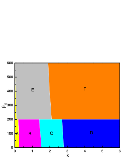
Firstly, we discuss the effect of isotropic 2D RD-SOC on the ground-state structure of spin- BEC without rotation in an optical lattice and a harmonic trap. Relevant studies Zhai ; Ho ; Sinha ; YZhang ; YLi showed that the mean-field ground state for a nonrotating spin-orbit-coupled spin- BEC in a harmonic trap has two typical phases, plane-wave phase (i.e. Thomas-Fermi (TF) phase) and stripe phase, depending on the nonlinear interactions. In Fig. 1, we give the ground-state phase diagram of nonrotating spin-orbit-coupled spin-1/2 BEC loaded in an optical lattice plus a harmonic trap with respect to the isotropic SOC strength () and the interspecies interaction . There are six different phases marked by A-F, which differ in terms of their density and phase distributions. In the following discussion, we will give a detailed description of each phase. The density and phase profiles of the B-F in Fig.1 are shown in Figs. 2(a)-2(e), respectively, where the interaction parameters are , for the first three columns, and for the last two columns. The isotropic 2D RD-SOC strengths are (a, d), (b), (c), and (e). Note that the odd and even rows present component 1 and component 2, respectively. We start from the case where SOC is sufficiently weak, which is indicated by the region A in Fig. 1. The A phase is a periodically modulated TF phase in which no vortex exists due to the very small isotropic RD-SOC (the density and phase profiles are not shown here for the sake of simplicity). In the case of relatively weak SOC, the system supports the B phase for and the E phase for , whose ground states are shown in Figs. 2(a) and 2(d), respectively. The ground state of the system exhibits obvious phase mixing in Fig. 2(a), where several ghost vortices are generated in the outskirts of each component (see the bottom two rows in Fig. 2(a)) and they carry no angular momentum LWen ; Kasamatsu2 ; LHWen . It is known that there are three fundamental types of vortices in cold atom physics: visible vortex, ghost vortex, and hidden vortex. The visible vortex is the ordinary quantized vortex which is visible in both the density distribution and the phase distribution and carries angular momentum Fetter2 . For the ghost vortex, it shows up in the phase distribution as a phase singularity and has no visible vortex core in the density distribution and carries no angular momentum Kasamatsu2 . Ghost vortices can be detected by the interference between two BECs, at least one of which contains ghost vortices. Like ghost vortex, the hidden vortex as a phase defect is invisible in the density profile but it carries angular momentum. Only after including the hidden vortices can the well-known Feynman rule be satisfied LWen ; LHWen , and the hidden vortices can be observed by using the scheme of free expansion. In Fig. 2(d) the two component densities display evident phase separation, where the topological defects in individual components composed of alternately arranged vortices (clockwise rotation) and antivortices (anticlockwise rotation) form rectangular vortex-antivortex lattices.
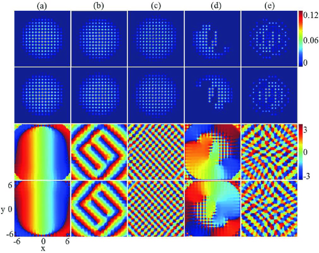
With the increase of isotropic RD-SOC strength, for the case of initial component mixing the C phase emerges as the ground state of the system, as shown by the region C in Fig. 1. The typical density and phase distributions of this phase are given in Fig. 2(b), where the ground-state density distributions of the system are similar to those in Fig. 2(a), but the ghost vortices disappear and ordinary visible vortices occur. The main reason is that the increased SOC offers more energy and angular momentum to the system. As the SOC is further increased, the D phase emerges, as displayed by the region D in Fig. 1. The density and phase distributions are shown in Fig. 2(c). The phase consists of 2D vortex-antivortex chain where vortices and antivortices form alternately arranged 2D chain structure in space. For the case of initial phase separation, with the increase of isotropic RD-SOC strength, the E phase transforms to the F phase in Fig. 1. Typical density and phase distributions of such a phase are shown in Fig. 2(e). The component densities keep separated (see the upper two rows in Fig. 2(e)) but the topological defects evolve into vortex-antivortex rings in which the vortices and antivortices are arranged alternately to form ring structures (see the lower two rows in Fig. 2(e)).
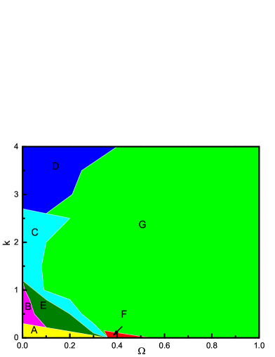
Secondly, we give the ground-state phase diagram spanned by the rotation frequency and the isotropic SOC strength in Fig. 3. For the case of rotating spin-orbit-coupled spin- BECs in a simple harmonic trap only, previous investigations XQXu ; Aftalion showed that the interplay between rotation frequency, SOC strength, and interparticle interactions can lead to various ground-state phases, such as half-quantum vortex, giant vortex, ringlike structures with triangular vortex lattices. For the present system, there are seven different phases marked by A-G, which differ in terms of their different density and phase distributions. In the following discussion, we will give a description for each phase. We start from the case where both the rotation and SOC are sufficiently weak, which is indicated by the yellow region A in Fig. 3. This phase is the periodically modulated TF phase without vortex in each component, which is the same with the A Phase in Fig.1. The typical density and phase profiles of the B phase, C phase and D phase in Fig. 3 are similar to those in Figs. 2(a), 2(b) and 2(c), respectively. At the same time, the density and phase profiles of the phases E-G in Fig. 3 are shown in Fig. 7(a) and Figs. 4(a)-4(b), respectively.
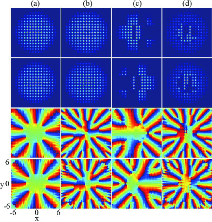
For relatively large rotation frequency but very weak SOC, the system exhibits a vortex ring where the vortices form a ring structure, indicated by red region F in Fig. 3. The main results are illustrated in Fig. 4(a). In Fig. 4, we consider the effect of isotropic 2D RD-SOC on the ground-state structure of the system with fixed rotation frequency . For initially miscible two-component BECs without SOC, i.e., , a vortex ring forms in each component and the density distributions are almost the same (see Fig. 4(a)), i.e., the F phase emerges. When the SOC strength further increases, the F phase transforms to the G phase, as shown in Fig. 3. The typical ground state is that more vortices occur in any of individual components and these vortices tend to form a triangular vortex lattice, where some of them enter the central region of the external potential (Fig. 4(b)). This G phase occupies the largest region of the ground-state phase diagram in Fig. 3. By comparison, for the case of initially immiscible BECs without SOC, the component densities are fully separated and the vortices form an irregular vortex cluster, which is displayed in Fig. 4(c). With the increase of SOC strength, e.g., , the system exhibits partial phase mixing in spite of the two components being separated initially, and the vortices and the vortex-antivortex pairs in each component constitute complex topological structure (see Fig. 4(d)), which is resulted from the competition among the repulsive interatomic interaction, SOC, rotation and the optical lattice.
Next, we move to the case of relatively small rotation frequency and weak SOC. In this regime, the system sustains E phase, which is denoted by region E in Fig. 3. Typical density and phase distributions of the E phase are displayed in Fig. 7(a). Obviously, the ground state is the known half-quantum vortex state, which is characterized by one vortex in one component and no vortex in the other component (see the third and fourth columns of Fig. 7(a)).
We find that the present system supports not only the line-like vortex excitation with respect to the spatial degrees of freedom of the BECs but also the point-like topological excitation (skyrmion excitation) concerning the spin degrees of freedom. The skyrmion is a type of topological soliton, which was originally suggested in nuclear physics by Skyrme to elucidate baryons as a quasiparticle excitation with spin pointing in all directions to wrap a sphere Skyrme . It can be viewed as the reverse of the local spin, which has been observed in many condensed-matter systems, such as quantum Hall system, liquid crystals, helical ferromagnets, liquid 3He-A, and BECs Anderson2 ; Wright ; XZYu ; CFLiu . The nonsingular skyrmion in two-component BECs is related to the Mermion-Ho coreless vortices Mermin , and the combination of SOC and rotation can cause various topological defects including circular-hyperbolic skyrmion CFLiu , giant skyrmion Aftalion , and so on. In Fig. 5 we display the topological charge density and the local enlargements of the spin texture for the ground state in Fig. 4(a). Here the topological charge is expressed by with the topological charge density . Our numerical calculation shows that the local topological charges in Figs. 5(b) and 5(c) approach , which indicates that the local topological defects in Figs. 5(b) and 5(c) are circular half-skyrmion (meron) and hyperbolic half-skyrmion, respectively. At the same time, the local topological charges in Figs. 5(d)-5(h) approach , which means that the local topological defects are circular-hyperbolic skyrmion [see Figs. 5(d)-5(f)], hyperbolic-radial(out) skyrmion [Fig. 5(g)] and hyperbolic-radial(in) skyrmion [Fig. 5(h)], respectively. Therefore the spin texture in Fig. 5(a) forms an exotic skyrmion-half-skyrmion lattice (skyrmion-meron lattice) composed of circular-hyperbolic skyrmions, hyperbolic-radial(out) skyrmion, circular half-skyrmions, and hyperbolic half-skyrmions. Essentially, the interesting topological structure is resulted from the interplay among the optical lattice, rotation and the interatomic interactions.
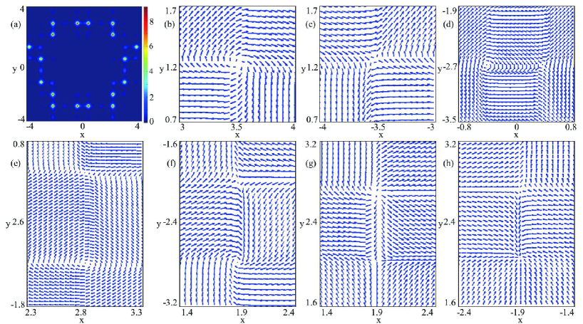
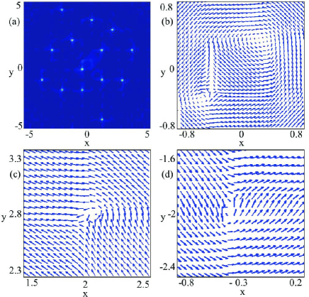
Figure 6(a) shows the topological charge density in the case of , , and , where the corresponding ground state is displayed in Fig. 4(b). The local spin texture are given in Figs. 6(b)-6(d). Our computation results demonstrate that the two local topological defects in Fig. 6(b) are a meron (half-skyrmion) pair composed of two circular merons (half-skyrmions) with each local topological charge being . In the mean time, the central meron pair is surrounded by some other spin defects (the full spin texture is not shown here in view of the limited resolution ratio and the brevity of the article). Our simulation shows that the local topological charge for each of the outer spin defects [e.g., see Figs. 6(c) and 6(d)] is , which implies that these outer spin defects are merons (half-skyrmions). Thus the circular meron pair and the half-skyrmions (merons) jointly form a complex meron lattice (half-skyrmion lattice), which has not been reported in previous literature. Physically, the asymmetry of the complicated topological structure (i.e., the composite meron lattice) is caused by the destruction of the SU(2) symmetry of the system in the presence of RD-SOC. The interesting and exotic spin textures as mentioned in Figs. 5 and 6 allow to be tested and observed in the future cold atom experiments.
Finally, we investigate the combined effects of RD-SOC, rotation and interatomic interactions on the ground state of the system. Figure 7 shows the density distributions and phase distributions for the ground states of rotating two-component BECs with RD-SOC in an optical lattice and a harmonic trap, where . The rotation frequencies for the case of initial phase mixing with and in Figs. 7(a) and 7(b) are and , and those for the case of initial phase separation with and in Figs. 7(c) and 7(d) are and , respectively. The columns from left to right denote , , , , and , respectively.
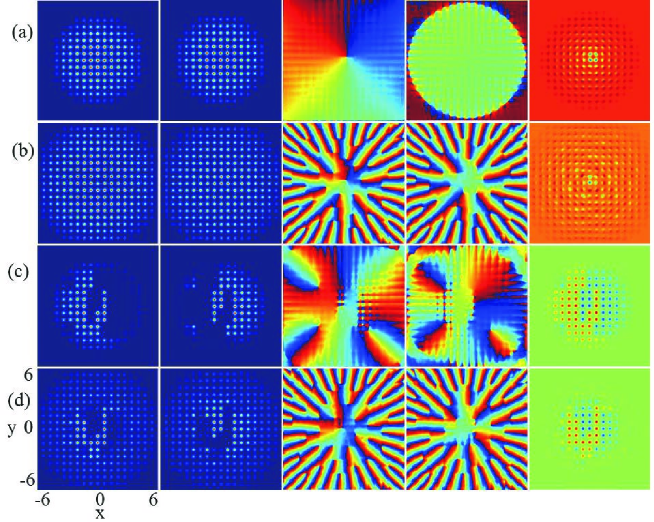
For the case of initial component mixing, as the rotation frequency increases from zero, the ghost vortices on the outskirts of the atom cloud enter the condensates and become visible vortices, where the phase defects tend to form a triangular vortex lattice for large rotation frequency [see Fig. 2(a), Fig. 7(a) and Fig. 7(b)] and the energy of the system reaches the minimum in the rotating frame. For the case of initial component separation, with the increase of rotation frequency, the topological structure of the system gradually evolves from a square vortex lattice composed of vortex-antivortex pairs into a complex triangular vortex lattice made of pure vortices, and the two component densities transform from full phase separation into partial phase mixing [see Fig. 2(d), Fig. 7(c) and Fig. 7(d)], which is quite different from the usual prediction results in rotating two-component BECs with or without SOC XQXu ; XZhou ; HHu ; Aftalion ; Fetter ; Kasamatsu . In addition, we find that the higher the rotation frequency is, the more the component densities of the BECs expand. This point can be understood. Physically, when the rotation frequency (with fixed RD-SOC and other parameters) increases, more angular momentum contributes to the system and leads to the creation of more phase defects and the expansion of the atom cloud, regardless of the initial state of the system being mixed or separated.
IV Ground-state structures and spin textures for the case of 1D RD-SOC
Now, we consider the ground-state structures of rotating two-component BECs loaded in an optical lattice and a harmonic trap in the presence of 1D RD-SOC. From Fig. 8, we see that the larger the 1D SOC strength or the rotation frequency is, the stronger the 1D SOC effect becomes. Taking the case of fixed 1D RD-SOC strength with and [see Figs. 8(c) and 8(d)] as an example, we first aim to discuss the influence of the rotation frequency on the ground-state structure of the system. Figs. 8(c) and 8(d) display the ground states of the system with and , respectively. For the low rotation frequency , there is an obvious visible vortex chain along axis in each component due to the 1D RD-SOC along the direction [see columns 3 and 4 from left to right in Fig. 8(c)], where the two component densities exhibit partial mixing and partial separation. As the rotation frequency increases to , more vortices are generated along the axis and the both sides of the central vortex chain, where the two component densities shows good phase mixing except that the densities along the axis display obvious phase separation [see columns 3 and 4 from left to right in Fig. 8(d)]. The physical mechanism is that large rotation frequency generates more energy and more angular momentum. Thus the -direction vortex chain caused by the combined effect of 1D RD-SOC and rotation can only carry finite energy and angular momentum, and the remaining energy and angular momentum are inevitably carried by the transverse vortices beside the axis.
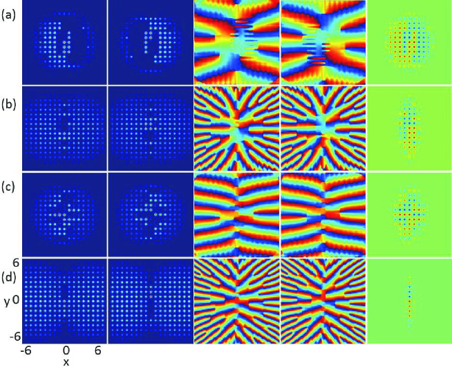
Then we consider the influence of 1D RD-SOC on the ground-state structure of the system. For instance, the rotation frequency is fixed as . From Figs. 8(a) and 8(c), it is shown that the stronger 1D RD-SOC enhances the creation of vortex chain and the formation of phase mixing. Similarly, for the BECs with 1D RD-SOC along the direction ( ), our simulation demonstrates that the density modulation occurs only along the direction. The above phenomena can be obtained and understood if one performs an unitary transformation, and , and sets or for the RD-SOC term.
The topological defects can be observed in a phase profile, but a better visualization is to use the pseudospin representation based on Eqs. (7)-(9). We can plot the functions and which reveal the presence of all the spin defects. The corresponding spin-density distributions of Figs. 8(a)-8(d) are shown in Figs. 9(a)-9(d), respectively. In the pseudo-spin representation, the red region denotes (spin-up) and the blue region denotes (spin-down). According to Eq. (9), the spin-density component is related to the density difference of the two components, therefore the variation tendency of the last row of Fig. 9 is consistent with that of the last column of Fig. 8. and obey neither even parity distribution nor odd parity distribution along the direction or the direction.
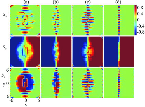
For further comparison, we choose Fig. 9(a) (and ) and Fig. 9(c) ( and ) as an example, and we can see that for the region of () the value of gets larger (smaller) with the increasing . Similarly, from Figs. 9(c) and 9(d), we can observe that for the region of () approaches () when the rotation frequency increases (see the middle row of Fig. 9). Thus we conclude that the spin component develops into two remarkable spin domains due to the increase of or . At the same time, an obvious spin domain wall forms on the boundary region between the two spin domains, which can be seen in the middle row of Fig. 9. In general, the spin domain wall for nonrotating two-component BECs is a classical Néel wall, where the spin flips only along the vertical direction of the wall. Whereas, our numerical simulation of the spin texture demonstrates that the spin in the region of spin domain wall flips not only along the vertical direction of domain wall (the direction) but also along the domain-wall direction (the direction), which indicates that here the domain wall is an unique Bloch wall instead of the conventional Néel wall. This domain wall is the product of the phase-separated two-component BECs in response to external rotation or RD-SOC, and reflects the influence of rotation or RD-SOC on the magnetism of BECs.
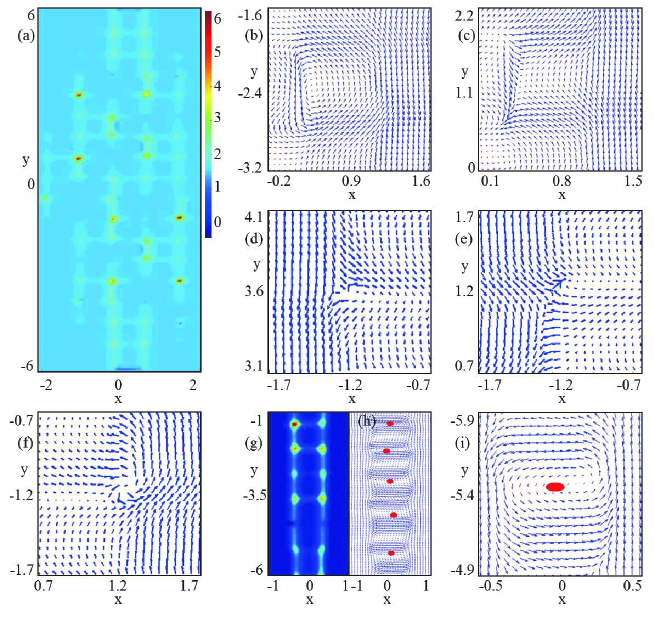
Displayed in Fig. 10(a) is the topological charge density for the parameters in Fig. 8(b). The typical local spin textures are shown in Figs. 10(b)-10(f). Our computation results show that the local topological charges in Figs. 10(b) and 10(c) are both while those in Figs. 10(d)-10(f) are all . Thus the spin defects in Figs. 10(b) and 10(c) denote an irregular circular skyrmion and an irregular hyperbolic skyrmion Kasamatsu ; CFLiu , respectively. At the same time, the topological defects in Figs. 10(d)-10(f) represent circular half-skyrmion (meron) Mermin , hyperbolic half-skyrmion and circular half-skyrmion, respectively. These topological defects alternately appear in the spin representation of Fig. 8(b) and constitute a complicated skyrmion-half-skyrmion (skyrmion-meron) lattice. In addition, we find that for strong 1D RD-SOC the system favors an exotic skyrmion chain (i.e., the skyrmions form a chain-like structure) which traverse the BECs. Figure 10(g) shows the topological charge density, where the ground state is given in Fig. 8(d). Figure 10(h) gives the corresponding spin texture, and the typical local amplification is exhibited in Fig. 10(i). Our numerical calculation shows that the local topological charge in Fig. 10(i) is and the total topological charge in Fig. 10(h) is . Therefore the spin structure of the system is a skyrmion chain that is composed of a string of elliptic skyrmions with unit topological charge in spin space as shown in Fig. 10(h). Obviously, the skyrmion configurations observed in the present system are remarkably different from the previously reported results in rotating two-component BECs with or without SOC XQXu ; XZhou ; HHu ; Aftalion ; Fetter ; Kasamatsu ; CFLiu .
V Conclusion
In summary, we have investigated the topological excitations of rotating two-component BECs with RD-SOC in a 2D optical lattice and a 2D harmonic trap. The effects of 2D RD-SOC, 1D RD-SOC, rotation, interatomic interactions and optical lattice on the topological structures of the ground states of the system are systematically discussed. Two ground-state phase diagrams for the nonrotating case and the rotating case are given with respect to the SOC strength and the interspecies interaction, and with respect to the rotation frequency and the SOC strength, respectively. Without rotation, a relatively weak isotropic 2D RD-SOC induces the formation of rectangular vortex-antivortex lattice for initially separated BECs, but strong 2D RD-SOC leads to generation of vortex-antivortex rings. For fixed isotropic 2D RD-SOC strength, the depth of optical lattice and the interaction parameters, the increase of rotation frequency can trigger the structural phase transition from square vortex lattice to irregular triangular vortex lattice and the system evolves from initial phase separation into phase mixing. For the case of 1D RD-SOC, the increase of SOC strength or rotation frequency may result in the creation of vortex chain and Bloch domain wall. In addition, the system sustains novel spin texture and skyrmion structures including an exotic skyrmion-half-skyrmion lattice (skyrmion-meron lattice), a complicated meron lattice (half-skyrmion lattice) and a skyrmion chain. These new topological excitations are quite from the predictions in the previous literature of rotating two-component BECs with or without SOC. Theoretically, the rotating spin-orbit-coupled BEC in an optical lattice plus a harmonic trap is feasible and can be achieved in principle. The experimental realization of the model Hamiltonian Eq. (1) is still a challenge within the current experimental conditions. However, considering that the present system has various novel physical properties, with the continuous development of experimental techniques, the system may be implemented in the future and its novel topological excitations are expected to be observed in experiments.
Acknowledgements.
L.W. thanks Professor Zhaoxin Liang and Professor Chaofei Liu for helpful discussions, and acknowledges the research group of Professor W. Vincent Liu at The University of Pittsburgh, where part of the work was carried out. This work was supported by the National Natural Science Foundation of China (Grant Nos. 11475144 and 11047033), the Natural Science Foundation of Hebei Province of China (Grant Nos. A2019203049 and A2015203037), and Research Foundation of Yanshan University (Grant No. B846).VI References
References
- (1) F. Dalfovo, S. Giorgini, L.P. Pitaevskii, S. Stringari, Rev. Mod. Phys. 71, 463 (1999).
- (2) I. Bloch, J. Dalibard, W. Zwerger, Rev. Mod. Phys. 80, 885 (2008).
- (3) V. Zapf, M. Jaime, C.D. Batista, Rev. Mod. Phys. 86, 563 (2014).
- (4) Y.J. Lin, K. Jiménez-García, I.B. Spielman, Nature 471, 83 (2011).
- (5) L.W. Cheuk, A.T. Sommer, Z. Hadzibabic, T. Yefsah, W.S. Bakr, M.W. Zwierlein, Phys. Rev. Lett. 109, 095302 (2012).
- (6) Z. Wu, L. Zhang, W. Sun, X.T. Xu, B.Z. Wang, S.C. Ji, Y. Deng, S. Chen, X.J. Liu, J.W. Pan, Science 354, 83 (2016).
- (7) L. Huang, Z. Meng, P. Wang, P. Peng, S.-L. Zhang, L. Chen, D. Li, Q. Zhou, J. Zhang, Nat. Phys. 12, 540 (2016).
- (8) J.-R. Li, J. Lee, W. Huang, S. Burchesky, B. Shteynas, F.C. Top, A.O. Jamison, W. Ketterle, Nature 543, 91 (2017).
- (9) H. Zhai, Rep. Prog. Phys. 78, 026001 (2015).
- (10) T.L. Ho, S. Zhang, Phys. Rev. Lett. 107, 150403 (2011).
- (11) S. Sinha, R. Nath, L. Santos, Phys. Rev. Lett. 107, 270401 (2011).
- (12) Y. Zhang, L. Mao, C. Zhang, Phys. Rev. lett. 108, 035302 (2012).
- (13) Y. Li, L.P. Pitaevskii, S. Stringari, Phys. Rev. Lett. 108, 225301 (2012).
- (14) T. Kawakami, T. Mizushima, M. Nitta, K. Machida, Phys. Rev. lett. 109, 015301 (2012).
- (15) S. Stringari, Phys. Rev. Lett. 118, 145302 (2017).
- (16) Y.V. Kartashov, V.V. Konotop, Phys. Rev. Lett. 118, 190401 (2017).
- (17) E. Ruokokoski, J.A.M. Huhtamäki, M. Möttönen, Phys. Rev. A 86, 051607(R) (2012).
- (18) X. Li, W.V. Liu, L. Balents, Phys. Rev. Lett. 112, 067202 (2014).
- (19) C. Wang, C. Gao, C.M. Jian, H. Zhai, Phys. Rev. Lett. 105, 160403 (2010).
- (20) X.Q. Xu, J.H. Han, Phys. Rev. Lett. 107, 200401 (2011).
- (21) X. Zhou, J. Zhou, C. Wu, Phys. Rev. A 84, 063624 (2011).
- (22) H. Hu, B. Ramachandhran, H. Pu, X.J. Liu, Phys. Rev. Lett. 108, 010402 (2012).
- (23) H. Sakaguchi, B.A. Malomed, Phys. Rev. A 96, 043620 (2017).
- (24) S. Gautam, S.K. Adhikari, Phys. Rev. A 97, 013629 (2018).
- (25) Y. Xu, L. Mao, B. Wu, C. Zhang, Phys. Rev. Lett. 113, 130404 (2014).
- (26) B. Ramachandhran, B. Opanchuk, X.J. Liu, H. Pu, P.D. Drummond, H. Hu, Phys. Rev. A 85, 023606 (2012).
- (27) X. Li, Q. Wang, H. Wang, C. Shi, M. Jardine, L.Wen, J. Phys. B 52, 155302 (2019).
- (28) J. Radić, T. A. Sedrakyan, I. B. Spielman, V. Galitski, Phys. Rev. A 84, 063604 (2011).
- (29) A. Aftalion, P. Mason, Phys. Rev. A 88, 023610 (2013).
- (30) A.L. Fetter, Phys. Rev. A 89, 023629 (2014).
- (31) Z.F. Xu, S. Kobayashi, M. Ueda, Phys. Rev. A 88, 013621 (2013).
- (32) A.C. White, Y.P. Zhang, T. Busch, Phys. Rev. A 95, 041604(R) (2017).
- (33) X.F. Zhang, M. Kato, W. Han, S.G. Zhang, H. Saito, Phys. Rev. A 95, 033620 (2017).
- (34) X.F. Zhang, R.F. Dong, T. Liu, W.M. Liu, S.G. Zhang, Phys. Rev. A 86, 063628 (2012).
- (35) L. Wen, H. Xiong, B. Wu, Phys. Rev. A 82, 053627 (2010).
- (36) J. Javanainen, H. Chen, Phys. Rev. A 89, 033613 (2014).
- (37) Y.V. Kartashov, V.V. Konotop, V.A. Vysloukh, Phys. Rev. A 97, 063609 (2018).
- (38) J.-G. Wang, S.-J. Yang, Eur. Phys. J. Plus 133, 441 (2018).
- (39) G. Grynberg, C. Robilliard, Phys. Rep. 355, 335 (2001).
- (40) M. Greiner, I. Bloch, O. Mandel, T.W. Hänsch, T. Esslinger, Phys. Rev. Lett. 87, 160405 (2001).
- (41) L.W. Clark, B.M. Anderson, L. Feng, A. Gaj, K. Levin, C. Chin, Phys. Rev. Lett. 121, 030402 (2018).
- (42) H. Pu, L.O. Baksmaty, S. Yi, N. P. Bigelow, Phys. Rev. Lett. 94, 190401 (2005).
- (43) S. Tung, V. Schweikhard, E. A. Cornell, Phys. Rev. Lett. 97, 240402 (2006).
- (44) J. Radić, A.D. Ciolo, K. Sun, V. Galitski, Phys. Rev. Lett. 109, 085303 (2012).
- (45) D.-W.Zhang, J.-P. Chen, C.-J. Shan, Z.D. Wang, S.-L. Zhu, Phys. Rev. A 88, 013612 (2013).
- (46) N. Goldman, G. Juzeliūnas, P. Öhberg, I.B. Spielman, Rep. Prog. Phys. 77, 126401 (2014).
- (47) Y.V. Kartashov, L.C. Crasovan, A.S. Zelenina, V.A. Vysloukh, A. Sanpera, M. Lewenstein, L. Torner, Phys. Rev. Lett. 93, 143902 (2004).
- (48) T. Mizushima, K. Machida, T. Kita, Phys. Rev. Lett. 89, 030401 (2002).
- (49) K. Kasamatsu, M. Tsubota, M. Ueda, Phys. Rev. Lett. 93, 250406 (2004).
- (50) K. Kasamatsu, M. Tsubota, M. Ueda, Phys. Rev. A 71, 043611 (2005).
- (51) W. Han, S.Y. Zhang, J.J. Jin, W.M. Liu, Phys. Rev. A 85, 043626 (2012).
- (52) C.F. Liu, H. Fan, Y.C. Zhang, D.S. Wang, W.M. Liu, Phys. Rev. A 86, 053616 (2012).
- (53) D.W. Peaceman, H.H. Rachford, J. Soc. Ind. Appl. Math. 3, 28 (1955).
- (54) L. Wen, Y. Qiao, Y. Xu, L. Mao, Phys. Rev. A 87, 033604 (2013).
- (55) K. Kasamatsu, M. Tsubota, M. Ueda, Phys. Rev. A 67, 033610 (2003).
- (56) L.H. Wen, X.B. Luo, Laser Phys. Lett. 9, 618 (2012).
- (57) A.L. Fetter, Rev. Mod. Phys. 81, 647 (2009).
- (58) T.H. R. Skyrme, Nucl. Phys. 31, 556 (1962).
- (59) P.W. Anderson, G. Toulouse, Phys. Rev. Lett. 38, 508 (1977).
- (60) D.C. Wright, N.D. Mermin, Rev. Mod. Phys. 61, 385 (1989).
- (61) X.Z. Yu, Y. Onose, N. Kanazawa, J.H. Park, J.H. Han, Y. Matsui, N. Nagaosa, Y. Tokura, Nature 465, 901 (2010).
- (62) N.D. Mermin, T.-L. Ho, Phys. Rev. Lett. 36, 594 (1976).