Lateral lattice coherence lengths in thin films of bismuth telluride topological insulators, with overview on polarization factors for X-ray dynamical diffraction in monochromator crystals
Abstract
In the supporting information file for article Dynamics of Defects in van der Waals Epitaxy of Bismuth Telluride Topological Insulators (J. Phys. Chem. C 2019, 123, 24818-24825, doi: 10.1021/acs.jpcc.9b05377), several topics on X-ray diffraction analysis of thin films were developed or revisited. A simple equation to determine lateral lattice coherence lengths in thin films stands as the main development (section S4 - Lateral lattice coherence length in thin films), while X-ray dynamical diffraction simulation in monochromator crystals stands as an interesting overview on how the ratio between and polarization components is affected by whether diffraction takes place under kinematical or dynamical regime (section S3 - Polarization factor).
Institute of Physics, University of São Paulo, São Paulo 05508-090, Brazil
1 S1 - Choice of asymmetric reflections
All allowed hkl reflections measured in a recent work1 are listed in Table S1. Forbidden reflections with khl indexes, hk regarding those in the Table S1, have null structure factors. They were also measured due to twinned domains in the films that are 60∘ rotated in azimuth regarding the film main lattice 2, 3.
| hkl | (Å-1) | (∘) | (∘) | (∘) | (∘) | hs | ks | ls | ||
|---|---|---|---|---|---|---|---|---|---|---|
| 1.950 | 13.831 | 31.889 | -60/60/180 | 7.26 | 0.679 | 815.0 | 1.25 | -0.75 | 1.25 | |
| 2.643 | 18.907 | 51.214 | -120/0/120 | 14.63 | 0.642 | 725.5 | 0.51 | 0.51 | 2.51 | |
| 3.468 | 25.160 | 17.280 | -120/0/120 | 7.26 | 0.593 | 695.5 | -0.75 | -0.75 | 3.25 | |
| 3.900 | 28.562 | 31.889 | -60/60/180 | 14.63 | 0.567 | 637.6 | 2.51 | -1.49 | 2.51 | |
| 4.500 | 33.482 | 13.233 | 79/199/319 | 7.26 | 0.535 | 626.1 | 1.25 | 3.25 | -2.75 | |
| 4.841 | 36.403 | 25.189 | -101/19/139 | 14.63 | 0.520 | 579.7 | 0.51 | -1.49 | 4.51 |
For thin epitaxial films undergoing Kinematical diffraction, the integrated intensity of a Bragg reflection is proportional to the beam footprint on the film surface, Eq. (S2). Then, to improve accuracy in determining atomic displacement parameters from integrated intensity data, the preference is for sets of reflections that have a common incidence angle . With the film surface normal direction , set collinear to the rotation axis of the 4-circle goniometer (Fig. 2a in the main text), the incidence angle can be obtained from the goniometer angles as . When the diffraction vector of an asymmetric reflection is placed in the incidence plane at the correct Bragg angle, and , leading to
| (S1) |
which is constant for all asymmetric reflections with the same l index in (001) films. Two sets of asymmetric reflections were chosen, hk5 and hk10 with incidence angles and , respectively.
Besides reflections with a common angle of incidence, film reflections must be far way from the substrate reflections to avoid extra intensity contributions in the film rocking curves (-scans) for integrated intensity measurements. The relative orientation of film and substrate lattices, as depicted in Fig. S1, is such that all allowed hk5 and hk10 film reflections are aligned along the surface normal direction with substrate reflections. However, their reciprocal lattice points (RLPs) fall in between those from the substrate lattice at a minimum distance of in reciprocal space, Fig. S1(e). The closest substrate diffracted beam propagates at from the incidence plane, as given by
for (), which is easily cut off by the vertical acceptance of of the detector system.
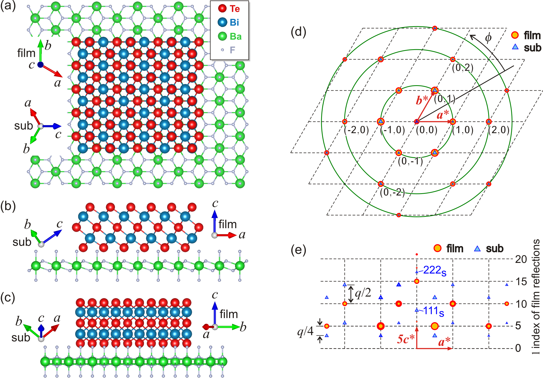
Choosing only reflections that have three-fold symmetry around the [001] direction is also important due to twinned domains often observed in the Bi2Te3 films. Since these domains are rotated by in azimuth regarding the main lattice of the films, reflections with six-fold symmetry are inevitably mixing contributions from the main lattice and from twinned domains. One the other hand, allowed reflections such as , , and are set apart by in azimuth, as given in Table S1, while reflections , , and are forbidden, unless receiving intensity contributions from twinned domains.
2 S2 - Integrated intensity
In small single crystals and thin epitaxial films, atomic displacement values can be determined by measuring the diffraction power of different hkl reflections 5; it is also known as integrated intensity of the diffraction curve as a function of the rocking curve angle . For thin films, this general expression can be written in terms of three parameters that are varying from one reflection to another: the scattering angle , the structure factor , and the number of unit cells within the diffracting volume for x-ray of wavelength . The scattering intensity by a single electron, , also depends on through the polarization factor since . In thin films of uniform thickness and negligible absorption, is proportional to the beam footprint for an incident x-ray beam of cross-section , leading to
| (S2) |
where is a constant for each sample. Since the number of accessible reflections in thin films are limited, the atomic displacement parameters ,7 for all elements have been restricted to the diagonal terms only, and with respect to in-plane (or lateral) and longitudinal directions, respectively. With this restriction the structure factor expression simplifies to where the diffraction vector has been splitted into two components: in the plane of the film, Figure. S1(d), and along the growth direction. The corresponding root mean square (rms) atomic displacements are then (lateral) and (longitudinal). Data fitting of experimental integrated intensities (peak areas) were carried out by using a simulated annealing (SA) algorithm 8, 9 to adjust , , and in the above equation, Eq. (S2). These fitting parameters were adjusted by minimizing the mean squared logarithmic error (MSLE) where and are experimental and simulated data points for each j-th reflection of diffraction vector in the set of reflections. After minimizing the MSLE function, relative variation of the experimental data due to atomic displacements have been displayed in the main text as
| (S3) |
3 S3 - Polarization factor
Unpolarized x-rays of wavevector , after scattering by electrons into wavevector have polarization factor where
| (S4) |
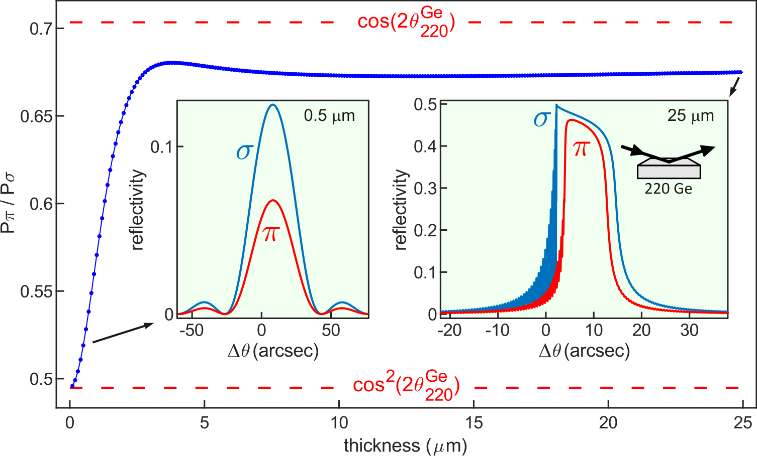
stands for each linearly polarized component of the incident wavefield vibrating along direction 10, 11, 12, 5. The two orthogonal components have been defined as and . By using and , we have that . Since for varying from 0 to in the unpolarized beam, is the well known polarization factor for scattering of unpolarized x-rays. It is also the polarization factor in the case of x-ray diffraction in small crystals such as thin epitaxial films diffracting according to the Kinematical theory. In large crystals such as the monochromator crystals undergoing a single Bragg reflection in reflection geometry, the intensity ratio between the and components in the diffracted beam is affected by crystalline perfection and x-ray absorption that can be different for each of these components.13 The exact polarization factor for a perfect Ge 220 monochromator and Cu radiation, , can be obtained by dynamical diffraction simulation,14 as shown in Fig. S2. For very thin crystals (m) or crystals with damaged surface diffracting kinematically, , while for perfect thick crystals (m), .
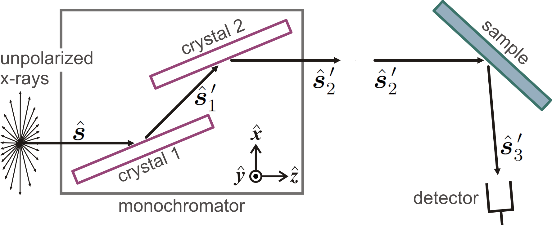
After the double collimating multilayer optic of the used diffractometer, the x-ray beam is still unpolarized before hitting the monochromator. In total, the detected x-rays undergo three Bragg reflections, two inside the monochromator and one in the sample, as depicted in Fig. S3. Then, the above equation, Eq. (S4), has to be applied recursively to each reflection, resulting in
| (S5) |
where and . By taking as the reduction ratio in the component after each 220 Ge reflection inside the monochromator, and as the Bragg angle of reflection hkl in the film,
| (S6) |
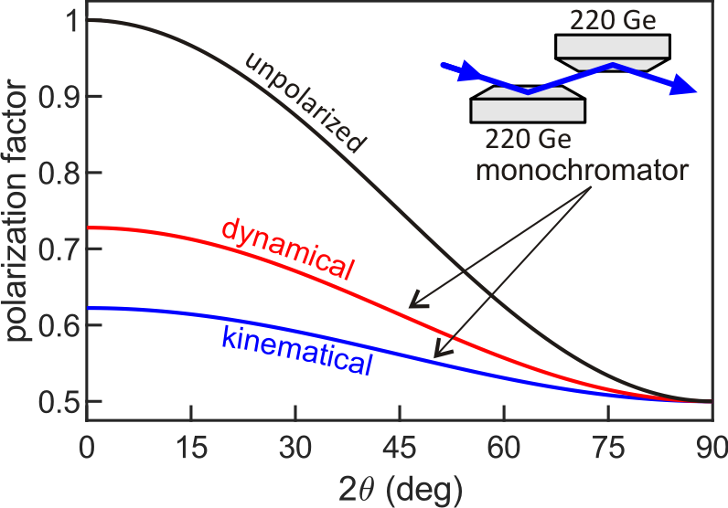
is the final polarization factor to be used when calculating the integrated intensities of the film’s hkl reflections. It implies that, the monochromator delivers x-rays with a relative amount of polarization in the incidence plane of the diffractometer. This component of -polarization is the fraction of incident x-rays in the sample that are in fact susceptible to the diffraction angle of the film reflections. Without accounting for polarization in the monochromator (), there would be a much more drastic reduction in the relative values of integrated intensities as the diffraction angle increases, as shown in Fig. S4. With the two-reflection monochromator, the relative amount of -polarization is in the range depending on the diffraction regime (kinematical or dynamical) of the monochromator crystals. The in-plane rms atomic displacement values reported in a recent work1 were determined for and the polarization factors listed in Table S1. By using instead (kinematical approach), all values are evenly increased by about 2 pm within the same error bars, i.e. 14.8 pm, 14.1 pm, 13.9 pm, and 14.1 pm would be 16.6 pm, 16.0 pm, 15.8 pm, and 15.9 pm, respectively.
4 S4 - Lateral lattice coherence length in thin films
Intensity distribution around reciprocal lattice points (RLPs) are related by Fourier transform to lattice coherence lengths inside the diffracting volume. In a perfect crystal domain, the coherence lengths are the sizes of the domain itself. But in epitaxial films, elastic strain and defects due to accommodation of lattice misfit at the film-substrate interface can lead to coherence lengths smaller than the sizes of the crystallographic domains. In other words, lattice coherence lengths can be smaller than domain sizes seen by morphological probes such as atomic force microscopy.
For diffraction vectors of asymmetric reflections, the film coherence lengths , , and are related to RLP broadening along in-plane directions
| (S7) |
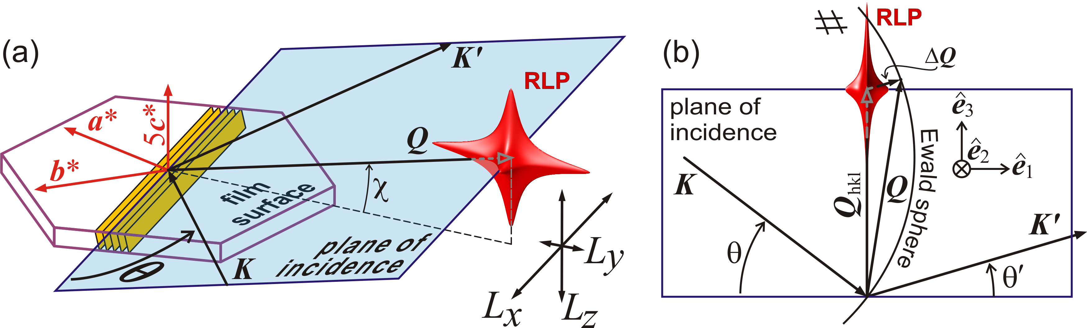
as well as along the growth direction , respectively. In diffraction geometry for very asymmetric reflections, as in Fig. S5(a) where , peak widths in rocking curve measurements (-scans) are most susceptible to the RLP broadening along in-plane directions, Eq. (S7), since along the crystal truncation rod, i.e. along , it is nearly perpendicular to the incidence plane.
Lattice imperfections with Burgers vectors parallel to the Bragg plane are invisible to the corresponding Bragg reflection 15, producing no reduction of coherence lengths perpendicular to the diffraction vector, as in the case of for which . On the other hand, misfit of film/substrate parameters reduces the coherence length according to the average lattice imperfection separation distance 16, 17
| (S8) |
where is the amount of misfit strain elastically accommodated in the absence of lattice mismatch , regarding the actual film and substrate lateral lattice parameters present in the sample, and respectively.
In rocking curve measurements, diffraction peak widths are determined by the convolution between Ewald sphere and RLP as a function of the rocking angle . If function describes the RLP broadening in reciprocal space, line profile of diffraction peaks can be calculated as 5
| (S9) |
where is the distance from the centre of the RLP given by the reciprocal lattice vector of reflection hkl. For an incident wavevector written as
in the reference frame [] of the incidence plane, as defined in Fig. S5(b) where , all physically possible wavevectors of diffracted x-rays (elastic scattering process) are accounted for as
even those rays going out of the incidence plane for which angle . Projection of in the frame earlier defined in Eq. (S7) is provided by
| (S10) |
allowing the RLP broadening due to finite lattice coherence lengths along , , and to be taken into account for asymmetric reflections with diffraction vector at an angle from the film surface, Fig. S5(a).
In one dimension, the Fourier transform of a finite lattice of length is the sinc function 5. Then, the modulus square of the normalized function
| (S11) |
has been chosen to describe the intensity distribution around the RLPs in Eq. (S9). Although it is possible to fit experimental peak widths by handling numerically the double integral in Eq. (S9), determination of the coherence lengths with this procedure can be very time consuming. Here, a different approach has been developed. Squared sinc functions have full width at half maximum (fwhm) given by (numerator comes from when ), which were projected in the incidence plane, and the corresponding peak widths in -scans obtained by using standard 2D Ewald construction in reciprocal space, e.g. Fig. S5(b). The resulting peak width is then calculated as
| (S12) |
where , , and . In Fig. S6 there is a comparison of peak widths calculated by the exact solution in Eq. (S9) and by the approach in Eq. (S12). Since the latter approach shows very good agreement with the exact solution and is much faster in terms of CPU time, it has been used to determine the coherence lengths from the experimental peak widths.
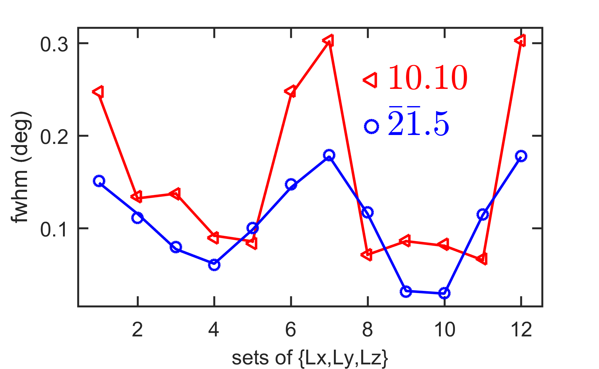
Coherence length values were adjusted by SA algorithm to minimize the mean square deviation function where and stand for experimental and calculated peak widths, respectively. is obtained from Eq. (S12). Subscript runs over the reflections in either hk 5 and hk 10 subsets of reflections. Uncertainties were estimated from the error bars in values as . The standard errors were obtained by measuring a few times equivalent reflections set apart by 120∘ in azimuth (Table S1).
5 S5 - Hybrid reflections
Hybrid reflections have been studied and applied to investigate heteroepitaxial systems since 1981 18, 19, 20, 21, 22, 23, 24, 25, 26, 27, 28, 29. However, only recently their occurance in epitaxial systems of hexagonal (001) films on cubic (111) substrates, such as Bi2Te3/BaF2, have been predicted and observed at scattering angles 30
| (S13) |
where and . For the pair of hybrid reflections recently measured,1 hybrids (peak f/s) and (peak s/f), both have and . By using Å as the cubic lattice parameter of BaF2 and Å as the hexagonal lattice parameter of the film, is close to the incidence angle used to excite these hybrids in symmetric diffraction geometry. However, each hybrid occurs at different azimuth. For the reference of azimuth defined in Fig. S1, peak f/s is centred at about and peak s/f at . Meshscans in and were carried out around these azimuths to proper determine the hybrid peak position in ; a detailed description on how to measure such hybrids can be found elsewhere 30. The split of a hybrid pair as function of the rocking curve angle is proportional to as given by
| (S14) |
is the in-plane component of the film diffraction vector and is the in-plane direction of the incident wavevector. For the case of hybrids (peak f/s) and (peak s/f), , which leads to the values of reported here.
6 S6 - Film composition
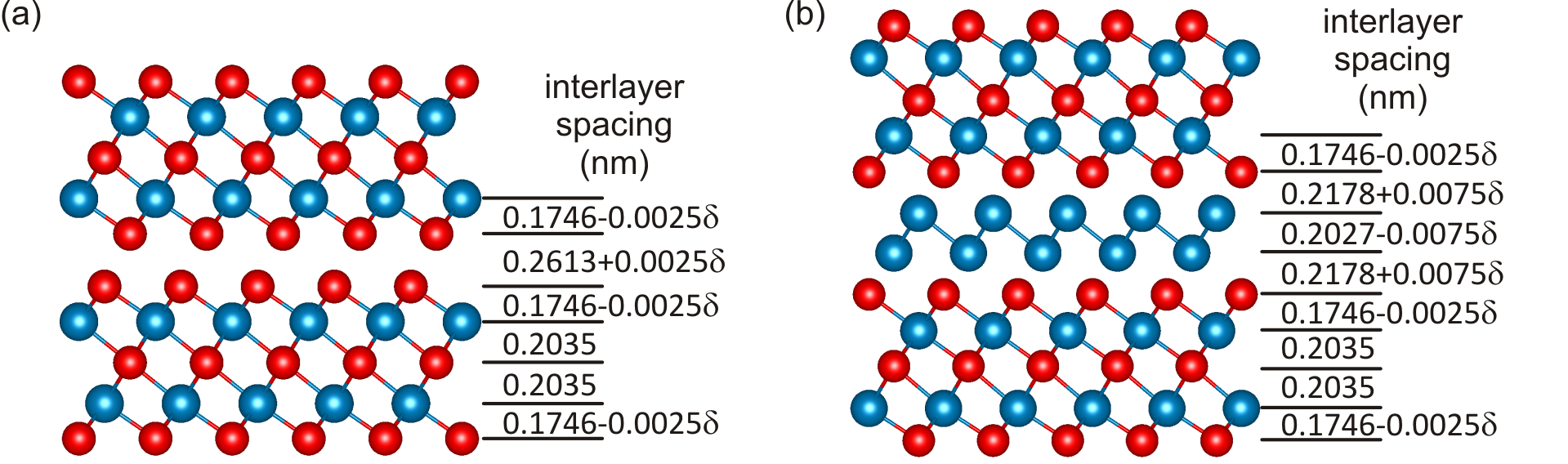
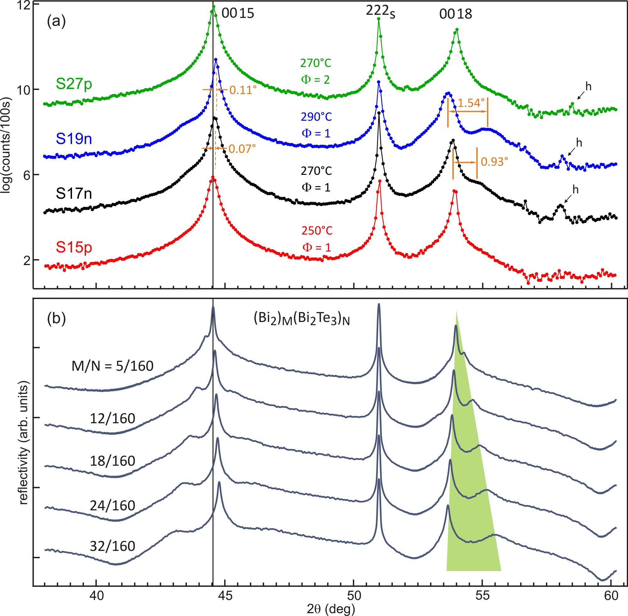
Films with composition have deficit of tellurium due to formation of bismuth bilayers (BLs) in the vdW gap between adjacent quintuple layers (QLs). X-ray diffraction simulation in model structures containing a number of BLs randomly distributed along the film thickness have been used to determine the actual composition of the films.4, 31, 32 In first order approximation, variation of interlayer spacing in the model structures as a function of were accounted for as shown in Fig. S7. By comparing experimental and simulated x-ray diffraction curves in Fig. S8, only two samples present features owing to the presence of BLs: shifting of peak whose position is determined by the mean interlayer spacing ;4, 2 and splitting of peak (shaded area in Fig. S8(b)) that is also proportional to according to (for in radians) 2, 31. By using this later formula with the values indicated in Fig. S8(a), samples S17n and S19n have films of compositions Bi2Te2.74 and Bi2Te2.58, respectively.
References
- Morelhão et al. 2019 Morelhão, S. L.; Kycia, S. W.; Netzke, S.; Fornari, C. I.; Rappl, P. H. O.; Abramof, E. Dynamics of Defects in van der Waals Epitaxy of Bismuth Telluride Topological Insulators. J. Phys. Chem. C 2019, 123, 24818–24825
- Fornari et al. 2016 Fornari, C. I.; Rappl, P. H. O.; Morelhão, S. L.; Abramof, E. Structural Properties of \ceBi2Te3 Topological Insulator Thin Films Grown by Molecular Beam Epitaxy on (111) \ceBaF2 Substrates. J. Appl. Phys. 2016, 119, 165303
- Fornari et al. 2016 Fornari, C. I.; Rappl, P. H. O.; Morelhão, S. L.; Peixoto, T. R. F.; Bentmann, H.; Reinert, F.; Abramof, E. Preservation of Pristine \ceBi2Te3 Thin Film Topological Insulator Surface After ex Situ Mechanical Removal of Te Capping Layer. APL Mater. 2016, 4, 106107
- Steiner et al. 2014 Steiner, H.; Volobuev, V.; Caha, O.; Bauer, G.; Springholz, G.; Holý, V. Structure and Composition of Bismuth Telluride Topological Insulators Grown by Molecular Beam Epitaxy. J. Appl. Cryst. 2014, 47, 1889–1900
- Morelhão 2016 Morelhão, S. L. Computer Simulation Tools for X-ray Analysis; Graduate Texts in Physics; Springer, Cham, 2016
- 6 University of São Paulo, Department of Applied of Physics. http://xraybook.if.usp.br/, routine fpfpp.m (accessed March 10, 2018)
- Kuhs 2003 Kuhs, W. F. In International Tables for Crystallography Volume D: Physical properties of crystals; Authier, A., Ed.; Springer: Netherlands, Dordrecht, 2003; pp 228–242
- Kirkpatrick et al. 1983 Kirkpatrick, S.; Gelatt, C. D.; Vecchi, M. P. Optimization by Simulated Annealing. Science 1983, 220, 671–680
- Kabova et al. 2017 Kabova, E. A.; Cole, J. C.; Korb, O.; López-Ibáñez, M.; Williams, A. C.; Shankland, K. Improved Performance of Crystal Structure Solution from Powder Diffraction Data Through Parameter Tuning of a Simulated Annealing Algorithm. J. Appl. Cryst. 2017, 50, 1411–1420
- Morelhão and Avanci 2001 Morelhão, S. L.; Avanci, L. H. Strength Tuning of Multiple Waves in Crystals. Acta Cryst. A 2001, 57, 192–196
- Morelhão and Kycia 2002 Morelhão, S. L.; Kycia, S. Enhanced X-ray Phase Determination by Three-Beam Diffraction. Phys. Rev. Lett. 2002, 89, 015501
- Morelhão et al. 2011 Morelhão, S. L.; Remédios, C. M. R.; Freitas, R. O.; dos Santos, A. O. X-ray Phase Measurements as a Probe of Small Structural Changes in Doped Nonlinear Optical Crystals. J. Appl. Cryst. 2011, 44, 93–101
- Authier 2003 Authier, A. Dynamical Theory of X-Ray Diffraction; Oxford University Press, Oxford, 2003
- Weckert and Hümmer 1997 Weckert, E.; Hümmer, K. Multiple-Beam X-ray Diffraction for Physical Determination of Reflection Phases and its Applications. Acta Cryst. A 1997, 53, 108–143
- Morelhão et al. 2000 Morelhão, S. L.; Härtwig, J.; Meier, D. L. Dislocations in Dendritic Web Silicon. J. Cryst. Growth 2000, 213, 288–298
- Merwe 1978 Merwe, J. H. V. D. The Role of Lattice Misfit in Epitaxy. Crit. Rev. Solid State 1978, 7, 209–231
- Herman et al. 2004 Herman, M. A.; Richter, W.; Sitter, H. Epitaxy: Physical Principles and Technical Implementation; Springer: Berlin, Heidelberg, 2004; pp 389–421
- Isherwood et al. 1981 Isherwood, B. J.; Brown, B. R.; Halliwell, M. A. G. X-ray Multiple Diffraction as a Tool for Studying Heteroexpitaxial Layers. J. Cryst. Growth 1981, 54, 449–460
- Morelhão and Cardoso 1991 Morelhão, S. L.; Cardoso, L. P. Simulation of Hybrid Reflections in X-ray Multiple Diffraction Experiments. J. Cryst. Growth 1991, 110, 543–552
- Morelhão and Cardoso 1993 Morelhão, S. L.; Cardoso, L. P. Analysis of Interfacial Misfit Dislocation by X-ray Multiple Diffraction. Solid State Commun. 1993, 88, 465–469
- Morelhão and Cardoso 1993 Morelhão, S. L.; Cardoso, L. P. Structural Properties of Heteroepitaxial Systems Using Hybrid Multiple Diffraction in Renninger Scans. J. Appl. Phys. 1993, 73, 4218–4226
- Morelhão et al. 1998 Morelhão, S. L.; Avanci, L. H.; Hayashi, M. A.; Cardoso, L. P.; Collins, S. P. Observation of Coherent Hybrid Reflection with Synchrotron Radiation. Appl. Phys. Lett. 1998, 73, 2194–2196
- Morelhão et al. 2003 Morelhão, S. L.; Quivy, A. A.; Härtwig, J. Hybrid and Effective Satellites for Studying Superlattices. Microelectron. J. 2003, 34, 695–699
- Morelhão and Domagała 2007 Morelhão, S. L.; Domagała, J. Z. Hybrid Reciprocal Space for X-ray Diffraction in Epitaxic Layers. J. Appl. Cryst. 2007, 40, 546–551
- Menezes et al. 2009 Menezes, A. S.; dos Santos, A. O.; Almeida, J. M. A.; Bortoleto, J. R. R.; Cotta, M. A.; Morelhão, S. L.; Cardoso, L. P. Hybrid Reflections in InGaP/GaAs(001) by Synchrotron Radiation Multiple Diffraction. Phys. Status Solidi B 2009, 246, 544–547
- Menezes et al. 2010 Menezes, A. S.; dos Santos, A. O.; Almeida, J. M. A.; Bortoleto, J. R. R.; Cotta, M. A.; Morelhão, S. L.; Cardoso, L. P. Direct Observation of Tetragonal Distortion in Epitaxial Structures Through Secondary Peak Split in a Synchrotron Radiation Renninger Scan. Cryst. Growth Des. 2010, 10, 3436–3441
- Domagała et al. 2016 Domagała, J. Z.; Morelhão, S. L.; Sarzyński, M.; Maździarz, M.; Dłużewski, P.; Leszczyński, M. Hybrid Reciprocal Lattice: Application to Layer Stress Determination in GaAlN/GaN(0001) Systems with Patterned Substrates. J. Appl. Cryst. 2016, 49, 798–805
- Smith et al. 2017 Smith, E. H.; King, P. D. C.; Soukiassian, A.; Ast, D. G.; Schlom, D. G. Hybrid Reflections from Multiple X-ray Scattering in Epitaxial Oxide. Appl. Phys. Lett. 2017, 111, 131903
- de Prado et al. 2017 de Prado, E.; Martínez-Tomás, M. C.; Deparis, C.; Muñoz-Sanjosé, V.; Zúñiga-Pérez, J. Hybrid Multiple Diffraction in Semipolar Wurtzite Materials. J. Appl. Cryst. 2017, 50, 1165–1173
- Morelhão et al. 2018 Morelhão, S. L.; Kycia, S.; Netzke, S.; Fornari, C. I.; Rappl, P. H. O.; Abramof, E. Hybrid Reflections from Multiple X-ray Scattering in Epitaxial Bismuth Telluride Topological Insulator Films. Appl. Phys. Lett. 2018, 112, 101903
- Morelhão et al. 2017 Morelhão, S. L.; Fornari, C. I.; Rappl, P. H. O.; Abramof, E. Nanoscale Characterization of Bismuth Telluride Epitaxial Layers by Advanced X-ray Analysis. J. Appl. Cryst. 2017, 50, 399–410
- Springholz et al. 2018 Springholz, G.; Wimmer, S.; Groiss, H.; Albu, M.; Hofer, F.; Caha, O.; Kriegner, D.; Stangl, J.; Bauer, G.; Holý, V. Structural Disorder of Natural Superlattices Grown by Molecular Beam Epitaxy. Phys. Rev. Materials 2018, 2, 054202