Channel Capacity Optimization Using Reconfigurable Intelligent Surfaces in Indoor mmWave Environments
Abstract
Indoor millimeter-wave (mmWave) environment channels are typically sparsely-scattered and dominated by a strong line-of-sight (LOS) path. Therefore, communication over such channels is in general extremely difficult when the LOS path is not present. However, the recent introduction of reconfigurable intelligent surfaces, which have the potential to influence the propagation environment in a controlled manner, has the potential to change the previous paradigm. Motivated by this, we study the channel capacity optimization utilizing RISs in indoor mmWave environments where no LOS path is present. More precisely, we propose two optimization schemes that exploit the customizing capabilities of the RIS reflection elements in order to maximize the channel capacity. The first optimization scheme exploits only the adjustability of the RIS reflection elements; for this scheme we derive an approximate expression which explains the connection between the channel capacity gains and the system parameters. The second optimization scheme jointly optimizes the RIS reflection elements and the transmit phase precoder; for this scheme, we propose a low-complexity technique called global co-phasing to determine the phase shift values for use at the RIS. Simulation results show that the optimization of the RIS reflection elements produces a significant channel capacity gain, and that this gain increases with the number of RIS elements.
Index Terms:
Channel capacity, multiple-input multiple-output (MIMO), indoor, mmWave, RIS.I Introduction
Over the last years, there has been a tremendous, almost exponential, increase in the demands for higher data rates. The main driving forces that constantly enhance these demands are the increasing number of mobile-connected devices and the appearance of services that require high data rates (e.g., video streaming, online gaming). Consequently, a key feature of novel wireless communication standards is the migration to higher frequencies, such as the mmWave frequency bands. These bands provide us with multi-GHz bandwidths and enable transmission data rates of multi-Gbps.
Among the proposed mmWave frequency bands, the 60 GHz band with up to 7 GHz (57-64 GHz) of available bandwidth worldwide [1] has gained significant interest in industry as well as in academia. Because of the large signal attenuation, caused by the high free space path loss (FSPL) and the oxygen absorption, communication in the 60 GHz band is implementable in practice only for short-range distances and will most likely be used for indoor environments [2]. The main characteristic of indoor mmWave communications is that the propagation channel exhibits a quasi-optical behavior with most of the signal energy being received along the LOS path[3]. This is due to high reflection losses and high path losses caused by the larger path length compared to the LOS path. However, the presence of different obstacles (e.g., furniture, walls) may easily block the LOS path. In this scenario, if the number of metallic surfaces (or surfaces with relatively low reflection losses) is low, it can be extremely difficult to establish a reliable communication link.
A possible approach to overcome this issue lies in the use of RISs. RISs transform a generally stochastic channel into a software-reconfigurable environment that actively participates in transmitting and processing information [4]. The key component to realize the RIS function is a software-defined meta-surface that is reconfigurable in a way to adapt itself to changes in the wireless environment [5, 6]. RISs consist of a large number of small, low-cost, and passive elements each of which can reflect the incident signal with an adjustable phase shift, thereby modifying the radio wave. Optimization of the wavefront of the reflected signals enables us to shape how the radio waves interact with the surrounding objects, and thus control their scattering and reflection characteristics. For this reason, the focus of this paper is on the utilization of the RIS elements’ phase adjustment capabilities to optimize the system performance in indoor mmWave communications.
A body of research work has very recently emerged which studies the design of RIS-assisted MIMO systems for conventional (i.e., non-mmWave) channels. In [7], an optimization scheme to enhance the receive signal-to-noise ratio (SNR) of a single-stream multiple-input single-output (MISO) system by jointly adjusting the RIS reflection elements and the transmit precoder was proposed. However, this optimization scheme is constrained to single-antenna receivers. An asymptotic analysis of RISs in MIMO multi-user systems was presented in [8] and it was shown that RISs enable performance gains that are comparable to the gains of massive MIMO systems. The energy-efficiency of RISs in multi-user communication was studied in [9], and energy-efficient designs for both the transmit power allocation and the phase shifts of the RIS elements were developed. In [10], the authors extended the concept of RIS communications to the realm of index modulation by introducing RIS space shift keying (SSK) and RIS spatial modulation (SM) schemes.
In spite of this high research interest, only a small number of papers consider the use of RISs in mmWave communications. In [11], the authors investigated the blockage problem and used an RIS to optimize the link outage probability for single-input single-output (SISO) systems in indoor mmWave environments. This approach was also validated by a hardware testbed for SISO communication via an RIS. However, the work of [11] only considered the scenario where the transmitter and receiver are each equipped with a single antenna. Also, the system design in [11] did not consider the use of phase precoding at the transmitter. The fundamental limits of utilizing RISs in mmWave MIMO positioning systems were investigated in [12]. The optimization scheme for a single-stream MISO transmission in mmWave communication systems was studied in [13]. In that paper, an expression for computing the optimal transmit precoding vector was derived. Since the hardware implementation of this precoding vector required the fully-digital hardware architecture which has a prohibitively high hardware complexity, the authors considered a mathematical approximation of this precoding vector that is implementable by the hybrid hardware architecture. Both transmit precoder hardware architectures require the use of variable gain amplifiers, which usually have a much higher hardware complexity than conventional amplifiers, to adjust the signal amplitude. Also, the aforementioned approximation is usually performed using a compressed sensing algorithm, which can significantly increase the computational complexity. In addition, the optimization scheme in [13] is also constrained to single-antenna receivers.
Against this background, the contributions of this paper can be summarized as follows:
-
•
We propose two schemes for channel capacity optimization for single-stream MIMO transmission systems utilizing RISs in indoor mmWave environments environments where no LOS path is present. Although these schemes do not in general yield the global optimum solution, they are based purely on signal phase adjustments and hence require only low-complexity hardware architectures, which makes them particularly suitable for mmWave communications.
-
•
The first optimization scheme utilizes only the adjustability of the RIS reflection elements for which we derive the optimal phase shift values. Also, we derive an approximate expression that simplifies the channel capacity calculation for this optimization scheme, and intuitively explains the connection between channel capacity gains and the system parameters.
-
•
The second optimization scheme utilizes jointly the adjustability of the RIS reflection elements and the transmit phase precoder to optimize the channel capacity. For this scheme, we develop a low-complexity technique called global co-phasing, to determine the appropriate phase shift values of the RIS reflection elements.
-
•
We show through channel capacity simulations that the proposed optimization schemes are particularly suitable for indoor mmWave communication systems with a large number of RIS elements.
Notation: Lowercase bold symbols denote column vectors; uppercase bold symbols denote matrices; and denote absolute value and -norm, respectively; and denote the argument of a complex number and the mean (expected) value of a random variable, respectively; and denote transpose and Hermitian transpose, respectively; denotes the imaginary unit; denotes the k-th element of the i-th row of matrix ; denotes the i-th column of matrix ; denotes the i-th row of matrix ; denotes a circularly symmetric complex Gaussian random variable of mean and variance .
II System Model

We consider a wireless communication system with transmit and receive antennas, which is depicted in Fig. 1. Both the transmit and receive antennas are placed in uniform linear arrays on vertical walls that are parallel to each other. The distance between these walls is denoted as . The heights of the transmit and the receive antenna array midpoints are and respectively. In simulations (see Section IV), and will take values from predefined uniform ranges whose mean values are and respectively. The inter-antenna separations of the transmit and the receive antenna array are and respectively. Also, one RIS is installed on the surface perpendicular to the antenna arrays (e.g., floor or other wall). It consists of reflection elements placed uniformly in one dimension and the separation between the adjacent RIS elements is . The distance between the midpoint of the RIS and the plane containing the transmit array is . We assume that the RIS elements are ideal and that each of them can independently influence the phase and the reflection angle of the impinging wave.
As the focus of this paper is on a single in-phase and quadrature (IQ) stream transmission in the considered communication system, the signal vector at the receive antennas is given by
| (1) |
where is the channel matrix, is the transmitted IQ symbol with the energy and is the transmit precoding vector which satisfies . The noise vector is distributed according to .
The element of the channel matrix that models signal propagation between the t-th transmit antenna and the r-th receive antenna via all reflection elements can be expressed as [14]
| (2) |
where is the distance between the -th RIS reflection element and the -th receive antenna, is the distance between the -th transmit antenna and the -th RIS reflection element, and is the phase shift induced by the -th RIS reflection element111Since the assumed inter-antenna separations are , the lengths of the antenna arrays are only a few centimeters. At the same time, the distances between a RIS and the transmit/receive antenna array are a few meters (i.e., significantly larger than the antenna array lengths). Therefore, all transmit signals that originate from different transmit antennas have almost the same incidence angles at an arbitrary RIS reflection element. Based on this and the small length of the receive antenna array, it is reasonable to assume that we can adjust the reflection angles of each RIS element, so that all transmit signals reflected from that element can be received by all receive antennas. In that case, the expression (2) holds true..
For ease of analysis, we normalize the channel coefficients by the FSPL corresponding to signal transmission from a transmit antenna placed at height to a receive antenna placed at height via a reflective element at the center of the RIS. This normalizing FSPL is equal to , where and . Taking into account that , the normalized channel coefficients are given as
| (3) |
where . With this approximation in place, the channel matrix can be expressed as
| (4) |
where we define matrices , and .
III Proposed Optimization Schemes
The channel capacity of single-stream systems is primarily determined by the receive SNR [15]. To be able to further increase the receive SNR while keeping the receiver hardware implementation of the proposed optimization schemes as practical as possible, we assume a receive signal combining which is realized as a summation of the signals from all receive antennas, i.e.,
| (5) |
In the sequel, we derive two optimization schemes which aim to enhance the channel capacity of single-stream transmission in indoor mmWave communications. The first optimization scheme utilizes only the phase adjusting capabilities of the RIS elements to optimize the channel capacity. The second optimization scheme jointly uses the RIS element phase adjusting capabilities and the transmit phase precoding for the optimization of the channel capacity.
III-A RIS-only Optimization Scheme
This optimization scheme is purely based on the RIS element phase adjusting capabilities, without considering any phase adjustment possibility of the transmit precoder. Hence, the precoding vector is modeled as an all-ones column vector and the resulting receive signal from (5) can be expressed as
| (6) |
The phase shift value of the l-th RIS reflection element should be chosen to satisfy
| (7) |
Substituting (7) into (6), we obtain
| (8) |
where the resulting noise signal is distributed according to .
Finally, the channel capacity of this RIS optimization scheme in an indoor mmWave environment can be calculated as
| (9) |
III-A1 Approximate Expression
In this subsection, we derive a closed-form approximate expression222This expression is valid only when the separations between the adjacent antennas are significantly smaller than the distance between the RIS and the transmit/receive antenna array. to simplify computation of the channel capacity in (9). To achieve this, we find an approximate expression for the value which appears in (8). The following derivation considers signal transmission via an arbitrary RIS element. Simulation results in Section IV show that this approximation enables very accurate results.
The -th row of corresponds to the approximate response333In the following channel response expressions, we neglect the influence of FSPL. of the channel between the transmit antenna array and the -th RIS reflection element, which is given as [16, pp. 347–349]
where is the distance between the midpoint of the transmit antenna array and the -th RIS reflection element, and is the angle of signal departure at the transmit antenna array (at the transmit antenna array midpoint). In a similar manner, the -th column of corresponds to the approximate response of the channel between the -th RIS reflection element and the receive antenna array, which is given as [16, pp. 347–349]
where is the distance between the -th RIS reflection element and the midpoint of the receive antenna array, and is the angle of signal arrival at the receive antenna array (at the receive antenna array midpoint). Now the channel matrix modeling communication via the l-th RIS reflection element (without optimizing the phase of the impinging radio waves) can be modeled by
If we sum all matrix elements from the previous expression, we obtain
Finally, an approximate expression that can be used to simplify the computation of (9) is given by
| (10) |
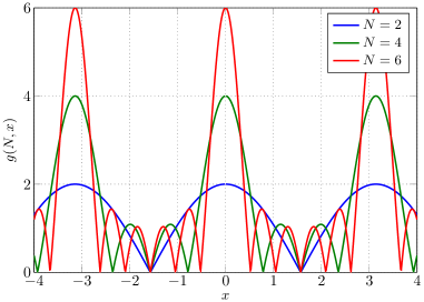
Observing the expression (10), we note that its right-hand side is a product of two terms, each of which can be represented by an instance of the auxiliary function , which is shown in Fig. 2. Therefore, in the following we elucidate the key properties of this function in order to provide insight regarding the behavior of (10). The auxiliary function has large main lobes that are centered at }, where the maximum value of this function is achieved. Between the main lobes, has a number of significantly smaller side lobes. Different lobes meet at points where the value of is approximately zero. With increasing , the number of side lobes increases and the main lobes become narrower. Hence, for a large there is a high probability that the value of for some arbitrary is small. In our particular case, this means that the expression (10) is more likely to have a small value, if and/or are large. Based on this, we conclude that the RIS-only optimization scheme is primarily suitable for implementation in communication systems with a limited number of transmit and receive antennas.
III-B Joint Optimization Scheme
In this subsection, we derive a joint optimization scheme that utilizes the phase adjusting capabilities of both the RIS elements and the transmit phase precoder. As we aim to have a precoder that is convenient for hardware implementation for mmWave communications, we consider only phase precoding solutions. Although phase precoding may not enable the system to achieve the best possible performance, its low-complexity hardware architecture makes it advantageous in mmWave communications. The transmit phase precoder is modeled by the precoding vector whose elements are determined by the phase values .
Since the channel capacity of the joint optimization scheme is given by
| (11) |
our optimization goal can be expressed as
| (12) |
First, we choose the transmit precoder phase values so that all terms are co-phased; thus we obtain
| (13) |
Now the optimization problem becomes
| (14) |
and it can be rewritten as
| (15) |
where is an all-ones vector. We note that the optimization problem (15) is analytically intractable and any exhaustive search solution incurs an extremely large search space. To overcome this issue, we introduce a simple sub-optimal technique to solve this optimization problem. Each summation term in (15) can be expressed as
| (16) |
We observe that the expression (16) achieves its maximum when the RIS element phase shift values enable co-phasing of individual summation terms. Since the optimization problem (15) consists a sum of different expressions (16), it is not possible to choose so that we have co-phasing in all expressions. Instead, we define the technique of global co-phasing which we implement for each independently. By global co-phasing we imply adjusting so that the sum of the phase deviations of the terms influenced by in (15) from the target phase has the minimum absolute value. For convenience we take that the target phase is 0. If we define
then the sum of the phase deviations is given by Since our goal is that the previous expression is 0, we finally obtain
| (17) |
It should be noted that the amplitude of the term influenced by in (15) is determined by . Also, this sum can be expressed in the form , where . Therefore, the amplitude of the term influenced by in (15) is more likely to be small for larger and only very limited capacity gains can be generally achieved when global co-phasing is implemented in this case. For this reason, the considered phase optimization scheme is most suitable for communication systems with a limited number of receive antennas.
IV Simulation Results

In this section, we present channel capacity simulation results for the RIS-only optimization scheme and the joint optimization scheme. We assume an indoor mmWave environment where no LOS path exists, and where the only non- (NLOS) paths are those provided by the RIS444Equivalently, other NLOS paths are assumed to provide negligible gain relative to that provided by the RIS.. In order to quantify the capacity gain due to the RIS optimization, we consider two benchmark schemes which utilize an RIS for reflecting the transmitted signal towards the receive antennas, but do not exploit the phase adjustment capabilities of the RIS. The first benchmark scheme, called co-phasing MIMO, is based on the implementation of only phase precoding at the transmitter and the receiver. The appropriate precoder phase adjustments and the channel capacity expression for this scheme are provided in Appendix A. The second benchmark scheme, called basic MIMO, has the simplest architecture among the considered schemes, and it does not use transmit/receive precoding or RIS phase adjustment to optimize the channel capacity. The channel capacity of this scheme can be calculated via
| (18) |
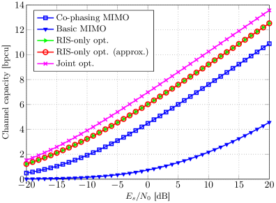
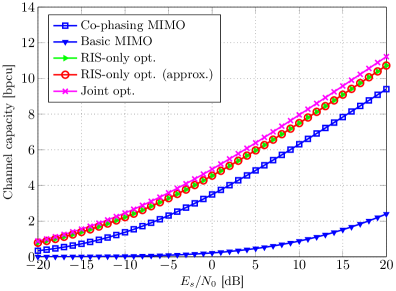
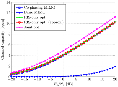
In the simulations, the setup parameters are (i.e., ), , , and . To obtain channel capacity results that are independent of a specific communication system geometry, we vary the antenna array heights and . More precisely, is chosen from a uniform distribution between 2 m to 3 m with a resolution of 2 cm (i.e., ), and is chosen from a uniform distribution between 0.8 m to 1.8 m with a resolution of 2 cm (i.e., ). The channel capacity is then averaged using a Monte Carlo approach.
In Fig. 3, we show the channel capacity simulation results for the RIS-only optimization scheme and the joint optimization scheme, versus the benchmark schemes (i.e., co-phasing MIMO and basic MIMO). In all cases, the joint optimization scheme achieves a higher channel capacity than the other considered schemes. As expected, the RIS-only optimization scheme has a lower channel capacity than the joint optimization scheme because it uses only the RIS elements for phase adjustment. However, with the increase of the number of RIS elements the channel capacity of the RIS-only optimization scheme becomes almost equal to the channel capacity of the joint optimization scheme (see Fig. 3(c)). In that case, the number of RIS elements is much larger than the number of transmit antennas, so that any channel capacity gain obtained through the transmit precoding is negligibly small compared to the channel capacity gain obtained through phase adjustment of the RIS elements. Increasing the number of receive antennas causes a channel capacity reduction for both optimization schemes, due to the reasons already explained in Section III. The same is valid for the number of transmit antennas of the RIS-only optimization scheme. Also, we notice that the approximate expression (10) for the channel capacity of the RIS-only optimization scheme gives approximately the same results as the exact channel capacity expression. Among the two benchmark schemes, basic MIMO always achieves the lower channel capacity because of the lack of hardware capabilities to optimize the channel capacity.
V Conclusion
In this paper, we studied the channel capacity optimization of single-stream transmission utilizing RISs in mmWave indoor environments without any LOS path, and proposed two optimization schemes. For the first optimization scheme, which targets only phase adjustments at the RIS, we derived an approximate expression which simplifies the channel capacity calculation and explains the connection between the achievable channel capacity gains and the system parameters. For the second optimization scheme that jointly utilizes the phase adjusting capabilities of both the RIS elements and the transmit phase precoder, we developed a low-complexity technique to obtain the phase shift values of the RIS elements. Simulation results show that both optimization schemes produce a very significant channel capacity gain, and that this gain increases with the number of RIS elements.
Appendix A Phase Adjustments for Co-phasing MIMO
Since co-phasing MIMO is based on the use of transmit and receive phase precoding, the resulting receive signal after the receive signal combining is given as
| (19) |
where and . Based on (19), the channel capacity expression for co-phasing MIMO can be written as
| (20) |
As the channel capacity is primarily determined by the value of , the considered phase precoders should be designed to maximize that value. First, we choose to co-phase the receive antenna signals before their combining (addition) and thus we obtain
| (21) |
Now we have
Applying the technique of global co-phasing, which is previously defined in Subsection III-B, to the elements of we finally obtain
| (22) |
References
- [1] R. Daniels, J. Murdock, T. Rappaport, and R. Heath, “60 GHz wireless: Up close and personal,” IEEE Microw. Mag., vol. 11, no. 7, pp. 44–50, Dec. 2010.
- [2] L. L. Yang, “60GHz: Opportunity for gigabit WPAN and WLAN convergence,” SIGCOMM Comput. Commun. Rev., vol. 39, no. 1, pp. 56–61, Dec. 2008.
- [3] A. Maltsev, V. Erceg, E. Perahia, C. Hansen, R. Maslennikov et al., “Channel models for 60 GHz WLAN systems,” Tech. Rep. IEEE 802.11-09/0334r8, May 2010. [Online]. Available: https://mentor.ieee.org/802.11/dcn/09/11-09-0334-08-00ad-channel-models-for-60-ghz-wlan-systems.doc
- [4] E. Basar, M. Di Renzo, J. de Rosny, M. Debbah, M.-S. Alouini, and R. Zhang, “Wireless communications through reconfigurable intelligent surfaces,” arXiv preprint arXiv:1906.09490, 2019.
- [5] K. Ntontin, M. Di Renzo, J. Song, F. Lazarakis, J. de Rosny et al., “Reconfigurable intelligent surfaces vs. relaying: Differences, similarities, and performance comparison,” arXiv preprint arXiv:1908.08747, 2019.
- [6] M. Di Renzo, M. Debbah, D.-T. Phan-Huy, A. Zappone, M.-S. Alouini et al., “Smart radio environments empowered by reconfigurable AI meta-surfaces: An idea whose time has come,” EURASIP J. Wireless Commun. and Netw., vol. 2019, no. 1, pp. 1–20, 2019.
- [7] Q. Wu and R. Zhang, “Intelligent reflecting surface enhanced wireless network via joint active and passive beamforming,” IEEE Trans. Wireless Commun., vol. 18, no. 11, pp. 5394–5409, Nov. 2019.
- [8] Q.-U.-A. Nadeem, A. Kammoun, A. Chaaban, M. Debbah, and M.-S. Alouini, “Large intelligent surface assisted MIMO communications,” arXiv preprint arXiv:1903.08127, 2019.
- [9] C. Huang, A. Zappone, G. C. Alexandropoulos, M. Debbah, and C. Yuen, “Reconfigurable intelligent surfaces for energy efficiency in wireless communication,” IEEE Trans. Wireless Commun., vol. 18, no. 8, pp. 4157–4170, Aug. 2019.
- [10] E. Basar, “Large intelligent surface-based index modulation: A new beyond MIMO paradigm for 6G,” arXiv preprint arXiv:1904.06704, 2019.
- [11] X. Tan, Z. Sun, D. Koutsonikolas, and J. M. Jornet, “Enabling indoor mobile millimeter-wave networks based on smart reflect-arrays,” in IEEE INFOCOM 2018 - Conf. on Computer Commun., 2018, pp. 270–278.
- [12] J. He, H. Wymeersch, L. Kong, O. Silvén, and M. Juntti, “Large intelligent surface for positioning in millimeter wave MIMO systems,” arXiv preprint arXiv:1910.00060, 2019.
- [13] P. Wang, J. Fang, X. Yuan, Z. Chen, H. Duan, and H. Li, “Intelligent reflecting surface-assisted millimeter wave communications: Joint active and passive precoding design,” arXiv preprint arXiv:1908.10734, 2019.
- [14] W. Tang, M. Z. Chen, X. Chen, J. Y. Dai, Y. Han et al., “Wireless communications with reconfigurable intelligent surface: Path loss modeling and experimental measurement,” arXiv preprint arXiv:1911.05326, 2019.
- [15] A. F. Molisch and M. Z. Win, “MIMO systems with antenna selection,” IEEE Microw. Mag., vol. 5, no. 1, pp. 46–56, Mar. 2004.
- [16] D. Tse and P. Viswanath, Fundamentals of Wireless Communication. Cambridge, UK; New York: Cambridge University Press, Jul. 2005.
| Replace this box by an image with a width of 1 in and a height of 1.25 in! | Your Name All about you and the what your interests are. |
| Coauthor Same again for the co-author, but without photo |