Liquid-liquid capillary replacement in a horizontal geometry: universal dynamics and replacement time
Abstract
Capillary invasion of a liquid into an empty tube, which is called capillary rise when the tube axis is in the vertical direction, is one of the fundamental phenomena representing capillary effects. Usually, the tube is actually filled with another pre-existing fluid, air, whose viscosity and inertia can be practically neglected. In this study, we considered the effect of the pre-existing fluid, when its viscosity is non-negligible, in a horizontally geometry. This geometry is free from gravity and thus simpler than the geometry of capillary rise. We observed the dynamics when a capillary tube that is submerged horizontally in a liquid gets in contact with a second liquid. An appropriate combination of liquids allowed us to observe that the second liquid replaces the first without any prewetting process, thanks to a careful cleaning of capillary tubes. Furthermore, we experimentally observed three distinct viscous dynamics: (i) the conventional slowing-down dynamics, (ii) an unusual accelerating dynamics, and (iii) another unusual dynamics, which is linear in time. We developed a theory in viscous regimes, which accounts well for the observations through a unified expression describing the three distinct dynamics. We also demonstrated a thorough experimental confirmation on the initial velocity of the replacement. We further focused on the replacement time, the time required for the invading fluid to replaces completely the pre-existing fluid in the horizontal geometry, which is again well explained by the theory.
I Introduction
Capillary rise, a key experiment in the field of interfaces, concerns liquids brought into contact with a thin tube. Then liquids generally rises in the tubes, up to a height resulting from a balance between capillarity and gravity. The dynamics towards equilibrium is known to be divided into three successive steps de2013capillarity : an initial regime dominated by inertia, an ensuing viscous regime, and a final gravity-viscous regime. The corresponding dynamics are successively linear in time (meaning the rising height scales with ), proportional to (the so-called Lucas-Washburn law), and exponentially relaxing to the static height. In all these regimes, air pre-existing in the tube can be ignored, but there are cases where the fluid initially present in the tube has a non-negligible role. For example, a recent study by Hultmark hultmark2011influence , using very long and thin tubes filled with air, evidences that the dynamics in the viscous regime significantly deviates from the usual Washburn law. These effects are amplified when the tube is initially filled by another liquid, as it happens in oil recovery where pores full of oil are invaded by an aqueous solution. Having in mind this field of applications, studies considered the case of complex fluids elliott1967dynamic ; hansen1971dynamic and tortuous geometries barenblatt1990Rocks ; gerritsen2005modeling – all situations where flows are forced instead of being spontaneous.
Spontaneous replacement of a liquid by another liquid was first addressed in 1946 by Eley eley1946dynamical , who discussed this question both in powders and in tubes. For a certain ratio of viscosities and pre-wetted tubes, dynamics was observed to be accelerating, an unusual fact in capillary phenomena, but this aspect was not studied further, the study focusing on extracting the surface tension between the two liquids. Later on, Mumley studied liquid-liquid rise, considering different prewetting states, and a broad range of viscosities mumley1986kinetics . A complete model was derived (including both liquid viscosity and gravity) giving an implicit solution, which was yet not compared with experiments. This liquid-liquid capillary rise was revisited in 2016 by Walls walls2016capillary , who derived similar implicit dynamics and focused on the early dynamics under gravity. Experiments confirmed the existence of an early linear regime, which does not originate from an inertial dynamics but from the viscosity of the displaced liquid.
Here we consider capillary invasion in a horizontal geometry, which we call “horizontal capillary replacement” to emphasize the role of a pre-existing fluid to be replaced by another. Although a horizontal geometry is simpler to model than capillary rise, there are very few data are available on this subject. A theoretical and numerical study budaraju2016capillary recently investigated the liquid-liquid horizontal capillary replacement, focusing on the influence of tapered tubes. Dealing quickly with the case of a straight tube, the study predicted an accelerated dynamics (observed in eley1946dynamical ) and a viscous-linear linear dynamics, but no comparison with experiments was presented. In the case where the displaced fluid is much less viscous than the invading fluid, experimental data with liquid-air can be found in the paper by Hultmark hultmark2011influence . As for the inverse viscosity ratio in horizontal geometry, there is surprisingly a complete lack of experimental data in the literature.
We investigate liquid-liquid horizontal capillary replacement, for a broad range of viscosity ratios. Thanks to the simple geometry, we analytically solve the dynamics in a closed form, which unifies three distinct viscous dynamics, which we all confirm experimentally: in addition to the conventional viscous slowing-down dynamics, the theory captures the viscous-linear dynamics and a viscous accelerating dynamics, which were mentioned theoretically in walls2016capillary ; budaraju2016capillary . In this study, we systematically compared the theory with experimental observations of the accelerating capillary replacement.
We also demonstrate a thorough comparison between the theory and our experimental data on the initial finite velocity, strengthening the previous work from walls2016capillary performed in vertical geometry. In addition, the horizontal geometry provides a new variable of great interest: the replacement time, that is, the time required to fully replace the liquid initially present in the tube. This characteristic time can be relevant for some industrial processes yet has not been discussed in the literature. In the present study, we predict and verify experimentally the value of this replacement time. We finally show how the initial presence of a small slug of the invading liquid (a case of practical relevance) modifies the dynamics of replacement.
II Experiment
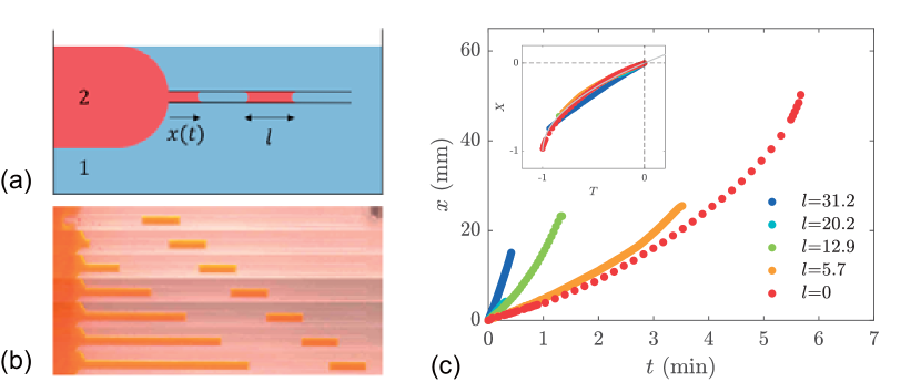
We fill a shallow transparent container (radius 14.5 cm, depth 9 mm) with liquid 1 and add a small amount of liquid 2 at the edge of the container, as illustrated in Fig. 1 (a). Liquid 2 forms a lens of a millimeter thickness, which we contact with a capillary tube immersed in liquid 1. The diameter ( to 0.95 mm) and length ( to 80 mm) of the tube are respectively smaller than the thickness of the lens and the diameter of the container. Tubes are made of glass and purchased from Hirschmann Laborgerate GmbH & Co. KG. Liquid 1 is a silicone oil with viscosity (KF-96, Shin-Etsu Chemical Co., Ltd), which can be varied between and 970 mPas. Liquid 2 is an 80 % ethanol aqueous solution (sterilization ethanol IP, KENEI Pharmaceutical Co., Ltd), with viscosity mPas.
A special care was needed to clean capillary tubes to perform reproducible experiments. The best performance was obtained by the following protocol: (1) soak tubes in an aqueous solution of Hellmanex II (Hellma GmbH & Co. KG), whose volume concentration is 2 %, at 35 ∘C for 60 minutes. (2) dry the tubes with a jet of gas using a canned spray (JBA-S481, Sanhayato Corp.). (3) store them in an airtight container, until they were used for the experiment. We avoided using ultrasonic bath because the cavitation process seemed to create inhomogeneity on the inside surface of the tubes. Indeed, when performing experiments with tubes cleaned with ultrasound, we noticed irregular stick-and-slip motions. (In contrast, as shown in Fig. 1 (c) below, all the invasion dynamics analyzed in this study were smooth, which may indicate was very small.)
As shown in the series of snapshots reported in Fig. 1 (b), liquid 2 penetrates a tube immediately after the tube touches a lens of liquid 2 at , where liquid 2 gradually replaces liquid 1 - the visual contrast between the liquids is amplified by the addition of a day (food red) in ethanol. Pictures were taken with a digital camera (Nikon D800E with AFS-S Micro Nikkor 60 mm 1.28 G ED) using the interval mode, and analyzed images with Tracker (The Open Source Physics Project). Typical results for the invasion length as a function of time are given in Fig. 1 (c).
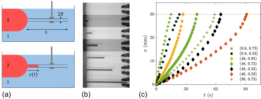
In most cases, the meniscus first propagates at a velocity of around 1 mm/s that logically decreases when increasing the viscosity of liquid 1. In addition, the meniscus accelerates significantly as it approaches the tube end. This behavior, together with a case of a linear dynamics (represented by green star symbols), markedly confronts with classical capillary impregnation, for which the meniscus slows down with time.
III Model
In the experiment, a tube is initially filled with liquid 1, at the cost of the interfacial energy between liquid 1 and the tube wall, per unit area. When the tube gets into contact with a lens of liquid 2, the liquid starts to replace liquid 1 if the interfacial energy between liquid 2 and the solid, , is smaller than , as in Fig. 1 (a) and (b). This replacement suggests that liquid 1 does not form any thin film during the invasion. Indeed, a film left by liquid 1 would cost the surface energy per unit area, an energy higher than the initial state, denoting as the interfacial energy between liquids 1 and 2. The energy change per unit area as the contact line moves by is , which gives a driving force (). Hence, the force driving the liquid invasion is given by
| (1) |
with
| (2) |
This can be written in the form on the basis of a force balance at the contact line when the spreading coefficient is non positive. Here, is the contact angle of a drop of liquid 2 on the solid when surrounded by liquid 1. In this case, the driving force is maximized for , which corresponds to a complete wetting condition for the invading liquid.
Motion is resisted by the Poiseuille viscous drag on tube walls, to which both liquids 1 and 2 contribute:
| (3) |
We assume that all other viscous and inertial effects can be neglected (see Discussion for more details) and just consider the balance . As a result, we can completely solve the dynamics, which yields:
| (4) |
Under the above assumption, this solution is valid irrespective of the relative values of and . Let us look at further simplifications of this general expression. In the limit , this solution approaches the simple form:
| (5) |
The physics of this linear dynamics is clear: in this limit, the pre-existing liquid is replaced by another invading liquid of same viscosity as invasion proceeds, so that the viscous force remains constant during the invasion process.
More generally, the initial invading velocity is obtained from eq. (4). We get
| (6) |
This expression for was recently derived in a previous study walls2016capillary as a limit of a non-explicit relation between and in a vertical geometry, where gravity matters.
By solving eq. (4) at in terms of , we also obtain a theoretical prediction for the time for the complete replacement:
| (7) |
Introduction of the renormalized length and time with allows us to simplify eq. (4) into a universal form:
| (8) |
IV Comparison between experiment and theory
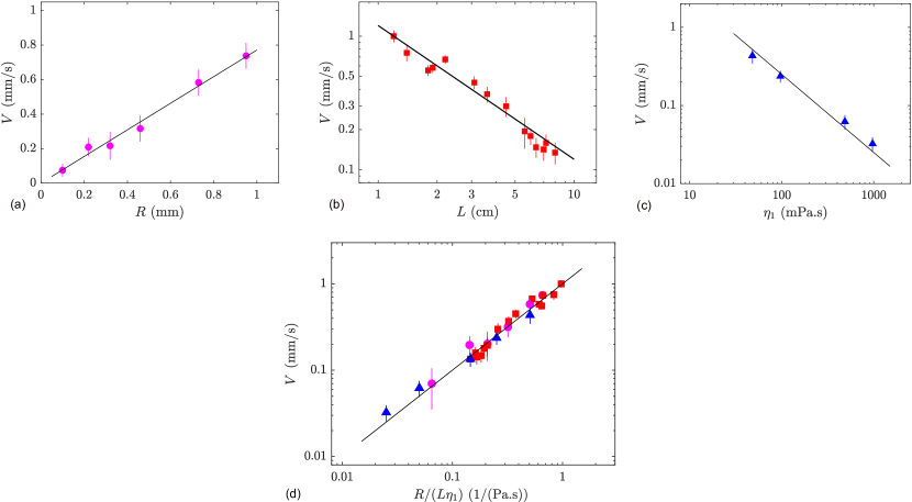
These different predictions can be compared with the data. We first test eq. (6) by plotting the initial velocity of invasion as a function of the tube radius (Fig. 2 a), of the tube length (Fig. 2 b), and of the oil viscosity (Fig. 2 c). In all cases, linear relationships are observed, as expected from eq. (6). The straight line that fits the data, goes through the origin in the linear plot (a) and has a slope in the log-log plots (b) and (c). All experiments can be collected in a single plot as in Fig. 2d to obtain an estimate of . The data collapse on a line representing the relation in agreement with eq. (6), where is found to be mN/m. This gives an estimate mN/m because eq. (6) suggests .
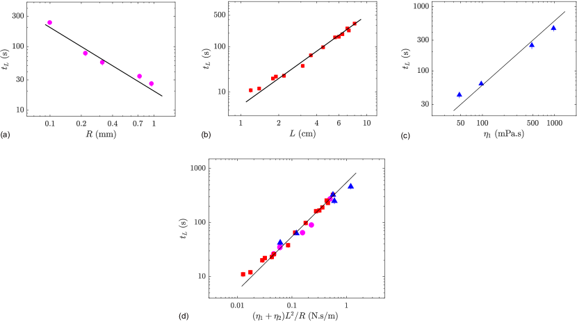
We secondly test eq. (7) in Fig. 3. The dependences of on , , and are confirmed in 3a to c. All data are collected in 3d to obtain another estimate of . The data collapse on a line representing in agreement with eq. (7), where mN/m, giving another estimate of : mN/m.
The two estimates for ( and mN/m) are consistent with each other, and are in agreement of our direct measurement of , which was a few mN/m. The direct measurement showed fluctuations. This is reasonable, because this quantity, i.e., , is sensitive to cleaning process. As a result, even though a special care was taken, fluctuates depending on the tube used. We consider this is the main source for small but visible deviations of the data from fitting lines in Figs. 2 and 3. (The slight deviation is small enough to demonstrate a good agreement between theory and experiment, but the quality of the collapse onto a master curve is more excellent in Fig. 4 below.) Note that quantitative determination of the liquid-liquid surface tension such as is still an issue of current study berry2015measurement .
However, this subtil issue of is avoided to test the universal dynamics predicted by eq. (8), as explained below. The test result is shown in Fig. 4, with properly rescaling the distance and time . As expected, all data collapse, with significantly less deviations, on a single master function nicely fitted by eq. (8).
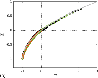
As announced, in Fig. 4, the analysis does not relay on the measurements of , which is sensitive to cleaning process. All the -dependences appear in eqs. (4) and (8) only through (remind in particular the definitions and eq. (7)), while this quantity can be measured directly for each tube through the experiment. This means that, if we use experimentally obtained to calculate the rescaled variable , we can escape a direct use of experimental values of . Thus, the convincing collapse exhibited in Fig. 4 indirectly justifies eq. (7). As expected from above discussions, if we instead use either of the two estimate of to obtain Fig. 4, the quality of collapse of the data deteriorates distinctively. Furthermore, estimated from the oil of lowest viscosity (0.8 mPas) was clearly different from the above two estimates. This could be because of partial dissolution of the oil in ethanol. However, even in this case, our analysis independent of allowed a clear collapse onto the master curve as demonstrated in Fig. 4.
V Discussion
In the raw data shown in Fig. 1(c), most of the data sets show that the dynamics accelerates as the invasion proceeds, as opposed to most of the theories known for capillary invasion. In fact, in the contexts including the imbibition of textured surfaces BicoEPL2001 , in addition to the conventional Washburn dynamics in which scales as in the viscous regime IshinoOkumura2008 , the linear dynamics has been discussed TaniPlosOne2014 and achieved delannoy2019dual , and other slowing dynamics in which scales as has been established in a various different geometries TangTang1994 ; JFM2011QuereCorners ; ObaraPRER2012 .
However, the physical mechanism for this unusual behavior is very simple. When the viscosity of the invading liquid is smaller than the previously existing liquid (), the total viscous drag is reduced as the invasion proceeds as clear from the physics employed in eq. (3).
In the opposite case of , we see the conventional slowing-down dynamics. In fact, eq. (4) is expressed as
| (9) |
which reduces to Washburn law in the limit . The final velocity at is given by
| (10) |
irrespective of relative magnitudes of and . At short times, the dynamics is always linear in : . In other words, eq. (4) predicts (i) the unusual accelerating dynamics when the invading liquid is less viscous, (ii) the conventional slowing-down dynamics when the invaded liquid is more viscous (as in the conventional case in which the invaded fluid is air), and (iii) another unusual dynamics, which is linear in time, when the two viscosities match with each other.
When discussing the universal equation in eq. (8), it is worthwhile noting that (i) when , the terminal time for the invasion corresponds to , but (ii) when , the terminal time corresponds to . This means that in the master curve in eq. (8) shown in Fig. 2(b), the dynamics proceeds from to for , while it does from to for . The variables and change their signs depending on the relative magnitudes of and .
The curvature effect of the lens of liquid 2 and inertia, which are neglected in the present theory, can be justified. The thickness of the lens scaling as with the gravitational acceleration is typically more than a few mm, which is significantly larger than the tube radius, because of the small factor . As for inertia, Reynolds number Re for the present problem scales as where and are the density and viscosity of the liquid in question and is the characteristic velocity scale. The extra factor emerges in this case, because the inertia term in Navier-Stokes equation scales as since scales as in the present case. In the present experiment, Re thus defined is always less than one for space and time resolution of the present experiment, and thus it is logical that all the data were successfully explained by the present theory.
We have neglected the following three viscous dissipations occurring at the entrance and exit points of the tube and at the contact line, which will be called the entrance, exit, and contact-line effects. The entrance effect is associated with a viscous flow outside the tube, which develops in the volume of the scale of tube radius around the entrance end of the tube, which scales as with representing the larger of and . The exit effect is the counterpart of the entrance effect at the exit, which scales as . The contact-line effect is associated with dissipation at the contact line, which scales as .
To look into these three effects, experiments with longer capillary lengths (thus we can use tubes with larger radius), which implies larger difference in surface energy and smaller difference in density, would an interesting future problem. In the present study, the agreement between theory and experiment suggests that these effects can be neglected for the parameter range we studied. However, we give further theoretical justification for , because the discussion is rather simple in this case and this condition is satisfied by most of the data in the present theory. The Poiseuille dissipation considered in the present theory scales as . This is represented by for . This implies the neglected three effects could matter only at long times. Thus, the correction due to the three effects is negligible for the initial dynamics represented by (Fig. 2), for the terminal time characterizing the overall dynamics (Fig. 3), and even for the entire dynamics represented by the relation with renormalized by (Fig. 4).
The force balance leading to eq.(5) and its integrated form were already discussed in eley1946dynamical . However, their interest is not in the invasion dynamics itself but in developing a technique to exploit the dynamics to determine the liquid-liquid surface tension. Accordingly, they did not derive the explicit closed expression for the invasion length in eq.(5), and thus did not discuss the universal feature of the dynamics elucidated in eq. (8). This remarkable feature was systematically confirmed by experiment in the present study. The discussion on the horizontal geometry in eley1946dynamical was very brief without showing any graphs and the contamination was a great problem: the reproducible results were obtained only when prewetting by the invading liquid was performed, which corresponds to a special case of zero-contact angle. They were rather interested in the capillary replacement in the vertical tube filled with grains, but they could not obtain the data in a reproducible way, showing a single graph obtained from ”a good experiment,” which was nonetheless rather consistent with their theory for the tube with grains. Note that the issue of contamination is resolved by the special cleaning process as already discussed.
VI Dynamics with a slug
In some practical situations, a small drop of the invading liquid could exist before the bulk invasion starts, as in Fig. 5(a). We consider the case in which a slug of liquid 2 is already in the tube, and surrounded by liquid 1. We call the slug’s length, and its distance to the free extremity of the tube, before the invasion starts (the slug initially occupies the tube in the position from to . In this case the invasion terminates when the front of the meniscus form the bulk phase of liquid 2 approaches the position , as shown in Fig. 5(a). This is because further displacement of the meniscus is hindered by the pinning of the slug at the edge of the tube.
The dynamics in this case may still be described by the unified expression given in eq. (8), for modified definitions: and . Here, and is given by eq. (7) with replaced by . The initial velocity given in eq. (6) is still valid if is replaced by . The universal expression, eq. (8), can also be expressed by the invasion time in this case, i.e., the time it takes for the new meniscus to go from to . This is because satisfies the relation . The systematic comparison of this theoretical prediction with experiment is shown in Fig. 5(c), which shows a reasonable data collapse onto the master curve.
VII Conclusion
In the present study, we focused on the capillary replacement in the horizontal geometry, when the viscosity of the pre-existing liquid is dominant. We solved the dynamics giving explicitly the functional dependence of the invaded length on the elapsed time . The explicit solution elucidates a universal feature of the replacement dynamics: the analytical expression unifies three distinctive dynamics, including non-conventional linear and accelerating dynamics, in addition to the conventional slowing dynamics. Furthermore, we derived a simple analytical result for the complete replacement time, the time required for the second liquid to completely replace the pre-existing liquid, which has never been discussed. We performed systematic experiments to test our theory and showed clear agreements between the theory and our data on the universal dynamics and the complete replacement time. We also experimentally confirm the initial invading velocity, which can be derived from our theory. Although the theory for the initial velocity has been available in the literature, a systematic confirmation has been lacking previously. The issues discussed in the present study should be significantly important for our fundamental understanding of wetting phenomena, and may be relevant to applications in various fields, which include microfluidics SquiresQuake2005 and petroleum industry HeleShawPetroleum2010 .
Acknowledgements.
J.A is grateful to David Quéré for hosting her in his lab, in collaboration with K.O, to work on an interesting subject, which gave birth to Sec. VI of the present article. K.O and J.A also thank Quéré for his remarks, experimental as well as theoretical, and for critical reading of drafts of the present article. This work was partly supported by JSPS KAKENHI Grant Number JP19H01859. J. A. thanks SAINT GOBAIN for financial support (”Innovative Process & Materials,” l’X - Ecole polytechnique and the Fondation de l’Ecole polytechnique).References
- (1)
- (2) De Gennes, P.-G., Brochard-Wyart, F. & Quéré, D. Capillarity and wetting phenomena: drops, bubbles, pearls, waves (Springer Science & Business Media, 2013).
- (3) Hultmark, M., Aristoff, J. M. & Stone, H. A. The influence of the gas phase on liquid imbibition in capillary tubes. Journal of Fluid Mechanics 678, 600–606 (2011).
- (4) Elliott, G. & Riddiford, A. Dynamic contact angles: I. the effect of impressed motion. Journal of colloid and interface science 23, 389–398 (1967).
- (5) Hansen, R. J. & Toong, T. Dynamic contact angle and its relationship to forces of hydrodynamic origin. Journal of Colloid and Interface Science 37, 196–207 (1971).
- (6) Barenblatt, G., Entov, V. & Ryzhik, V. Theory of Fluid Flows Through Natural Rocks (Spreinger, 1990).
- (7) Gerritsen, M. G. & Durlofsky, L. J. Modeling fluid flow in oil reservoirs. Annu. Rev. Fluid Mech. 37, 211–238 (2005).
- (8) Eley, D. & Pepper, D. A dynamical determination of adhesion tension. Transactions of the Faraday Society 42, 697–702 (1946).
- (9) Mumley, T. E., Radke, C. & Williams, M. C. Kinetics of liquid/liquid capillary rise: I. experimental observations. Journal of colloid and interface science 109, 398–412 (1986).
- (10) Walls, P. L., Dequidt, G. & Bird, J. C. Capillary displacement of viscous liquids. Langmuir 32, 3186–3190 (2016).
- (11) Budaraju, A., Phirani, J., Kondaraju, S. & Bahga, S. S. Capillary displacement of viscous liquids in geometries with axial variations. Langmuir 32, 10513–10521 (2016).
- (12) Berry, J. D., Neeson, M. J., Dagastine, R. R., Chan, D. Y. & Tabor, R. F. Measurement of surface and interfacial tension using pendant drop tensiometry. Journal of colloid and interface science 454, 226–237 (2015).
- (13) Bico, J., Tordeux, C. & Quéré, D. Rough wetting. Europhys. Lett. 55, 214–220 (2001).
- (14) Ishino, C. & Okumura, K. Wetting transitions on textured hydrophilic surfaces. Eur. Phys. J. E 25, 415–424 (2008).
- (15) Tani, M. et al. Capillary rise on legs of a small animal and on artificially textured surfaces mimicking them. Plos One 9, e96813 (2014).
- (16) Delannoy, J., Lafon, S., Koga, Y., Reyssat, É. & Quéré, D. The dual role of viscosity in capillary rise. Soft matter 15, 2757–2761 (2019).
- (17) Lei-Han Tang & Yu Tang. Capillary rise in tubes with sharp grooves. J. Phys. II France 4, 881–890 (1994).
- (18) Ponomarenko, A., Quéré, D. & Clanet, C. A universal law for capillary rise in corners. J. Fluid Mech. 666, 146–154 (2011).
- (19) Obara, N. & Okumura, K. Imbibition of a textured surface decorated by short pillars with rounded edges. Phys. Rev. E 86, 020601(R) (2012).
- (20) Squires, T. M. & Quake, S. R. Microfluidics: Fluid physics at the nanoliter scale. Rev. Mod. Phys. 77, 977 (2005).
- (21) Shad, S., Salarieh, M., Maini, B. & Gates, I. D. The velocity and shape of convected elongated liquid drops in narrow gaps. J. Petroleum Sci. Eng. 72, 67–77 (2010).