Equivalence of reflection paths of light and Feynman paths in stacked metasurfaces
Abstract
We show the existence of virtual polarization states during the interaction of modes in metasurface stacks. In support of our findings we experimentally realize a metasurface stack, consisting of an isotropic layer of nano-patches and an anisotropic layer of nano-wires. Utilizing an analogy to the interaction of electrons at junctions in mesoscopic electron transport via Feynman paths, we present a semi-analytical description of the modal interaction inside this stack. We then derive a series of all possible reflection paths light can take inside the metasurface stack.
pacs:
1234I Introduction
The concept of metasurfaces has permeated many aspects of technological advancement in photonics [1, 2, 3, 4, 5, 6, 7]. Commonly, metasurfaces comprise artificial two-dimensional arrangements of sub-wavelength structures or particles [8, 9]. They promise arbitrary control of light [10, 11, 12] and the creation of precisely engineered photon states [13, 14, 15, 16]. Recent examples of metasurface applications, ranging from hyperspectral imaging [17, 18] to holography [19, 20, 21], lensing [22, 23, 24] and quantum photonics [15, 16], substantiated that promise.
Moreover, metasurfaces can explore links between different disciplines of physics, with recent advances on so called bound states in the continuum as prominent examples [25, 26, 27, 28]. Similarly, metasurfaces can facilitate the combination of different physical processes in order to gain highly complex optical functionality [29, 30].
Many studies suggest it to be beneficial to combine different metasurfaces in multi-layered stacks [31, 32, 33, 34]. A recent example enabled multi-wavelength meta-lensing by combining geometrically independent dielectric metasurfaces [22]. Another work proposed cascading multiple layers of graphene with dielectric spacer layers to create a broadband optical absorber [35].
When light propagates through a stack, metasurfaces interact through inter-layer coupling. Adjacent metasurfaces couple either dominantly in the near-field [22, 32] or in the far-field [34, 36, 31]. The coupling of near-fields depends on the structures of the metasurface and their local wavelength dependent resonances [14, 5, 29]. Far-field coupling, on the other hand, does not depend on any local resonance of the metasurfaces. Here, the only interaction mechanism between the metasurfaces is of a Fabry-Perot type [34, 37, 36, 31]. Due to the resonant characteristic of this mechanism it modifies the far-field coupling of the modes to adjacent metasurfaces [36, 31]. Hence, we call this type of coupling modal coupling. Both numerical [34] and semi-analytic [36] simulations of far-field coupled metasurfaces reveal this phenomenon as part of the overall stack response. However, the actual interaction process during propagation through a stack is irretrievable from the overall response and, thus, remains hidden.
We aim to derive an interaction picture of stacked metasurfaces by expanding the modal interaction into a series of interfering reflected modes. In particular, we explore the interaction of modes inside a stack consisting of both an isotropic layer of gold nano-patches and an anisotropic layer of gold nano-wires. We analyze how isotropic and anisotropic modes contribute to the interaction and how they influence the total response. Finally, we reveal the existence of virtual polarization states during the modal interaction of the stack.
This work was motivated by the concept of electron scattering paths in mesoscopic solid state physics [38, 39]. Here, we attempt to compare and partially transfer this concept to the physics of nano-optics in the specific case of metasurface stacks.
The study of conduction in mesoscopic systems uses descriptive concepts equivalent to the aforementioned modal coupling in metasurface stacks [40, 41, 42]. Specifically, the process of electron scattering at junctions in mesoscopic structures can be considered analogously to the scattering of light at nano-structures [42, 43, 44].
Scattering processes can be described by a set of connected ports in or out of which particles or waves can be transmitted or reflected [40, 45]. In the case of mesoscopic electron transport this is the interaction of electrons from different leads at a given junction. Whether an electron is transmitted or reflected into a specific port or not is given by a probability [46, 40, 47]. Thus, for each combination of ports and whether the interaction results in transmission or reflection there exists a certain combined probability. When a scattering process is complete the final path an electron took can be described as a sum of all its possible paths, weighted by their probability for a given initial port [39]. Therefore, these paths give a picture of the interaction during the scattering process. In electron scattering theory they represent what is sometimes called the ’Feynman paths’ of the system [38, 39].
Similar to the scattering of electrons at junctions the interaction of light with metasurfaces can be formulated as a scattering problem and described by a set of connected ports [45]. Using scattering matrices (S-matrices) these ports describe the transmitted and reflected modes in different diffraction orders and polarization states [45, 33]. Additionally, the scattering ports encode whether a mode propagates from front to back of a metasurface or vice versa. Here, we focus on the interaction in modally coupled stacks and establish our model based on the fundamental mode approximation (FMA) [48, 49]. The FMA is valid if the constituent metasurfaces of the stack are homogeneous [50] and their separation is large enough such that adjacent metasurfaces only couple via fundamental modes [33].
II Theory of stacked metasurfaces in the fundamental mode approximation
Homogeneity implies that both the structures of a metasurface and their lateral separation are smaller than the wavelength of incident light. Furthermore, in the case of a metasurface with periodically arranged structures a fundamental mode is given by the zeroth diffraction order for perpendicularly incident light. If coupling is dominated by fundamental modes, higher diffraction orders have decayed evanescently, which is what the FMA implies [33].
In the FMA regime, the metasurfaces of a stack can each be described by four ports, representing transmission and reflection in two directions. An S-matrix representing the th layer then takes the form of a block matrix of Jones matrices for reflection and transmission [45, 33]. The amplitudes of its complex coefficients are the optical equivalents of the scattering probabilities of electrons from different leads at a junction[40, 38]. For light the scattering coefficients additionally distinguish polarization states in a given basis [51].
In order to denote an S-matrix to a complete stack of layers we can employ Redheffer’s star product [52] to combine the S-matrices of each layer such that [45, 33]
| (1) |
In this notation light propagates along the z-axis from metasurface 1 to . Each occurrence of the star product gives an overlap of the transmission functions of adjacent metasurfaces and includes all contributions of reflections between them. Mathematically, these contributions are represented by a reflection kernel of the form
| (2) |
marking matrices with a hat and defining the two-dimensional identity as . Here, is the Jones-matrix for reflection of layer when propagating back to front, as referred to by superscript b, and of layer when propagating from front to back, as referred to by superscript f. The reflection kernels contain exactly the Fabry-Perot type interactions of modally coupled metasurfaces. For a detailed picture of this interaction process it is therefore necessary to decompose it into its individual reflection paths.
III Reflection paths in stacked metasurfaces
III.1 Geometric expansion of stacked S-matrices
In the following we will introduce the mathematical approach we employ to find individual reflection paths during the modal interaction between metasurfaces.
We can expand the reflection kernel of the star product of two S-matrices () into a geometric matrix series 111If it is invertible and its block-matrix elements do not take values . This is usually the case for physical systems including absorption., such that
| (3) |
Then, each block matrix of a stacked S-matrix can be written as a matrix series
| (4) |
where are the S-matrix’s block indices.
In optics of stratified media such an expansion is generally known as a Bremmer series [54, 44]. It leads to the optical WKB (Wentzel, Kramers, Brillouin) approximation of the Helmholtz equation for one-dimensionally inhomogeneous media [54]. For the much more involved case of stacked metasurfaces we separate the response of the stack into a leading order term (i.e. the WKB term) and a series of consecutive interferometric terms. For two adjacent layers and front to back propagation this takes the form of
| (5) |
for transmission and
| (6) |
for reflection. The infinite power series of reflection matrices contains all possible paths light can take between layers after consecutive reflections. For coherent excitation these paths will interfere, including the leading transmissive term. However, separating the pure transmission from inter-layer reflections allows us to analyze how these reflection paths influence the final result.
For more than two layers, we need to expand this concept to an arbitrary number of layers. Using the associativity of the star product [52] eqs. (5) and (6) can be generalized to layers by applying each new layer to all the previous ones combined. For this, we introduce the multi-index , denoting all modal contributions from the 1st to the th layer. A transmission or reflection matrix equipped with includes all paths and recurring reflections up to the th layer, excluding those from following layers, and so forth. Imagining the propagation through a stack iteratively this is equivalent to successively connecting the scattering ports of each following layer to the input and output ports of all previous layers combined. Obeying the correct propagation directions (forward and backward) we thereby cascade all possible paths through a stack until the final output port to its substrate.
Then, the transmission through an -layer stack can be written as
| (7) |
using the compact index notation . The occurring reflection matrices can be found recursively. Given the meaning of the multi-index we also have to obey the order of products in eq. (7). In the context of forward propagation, each backward reflection matrix has its own frame of reference within the layer system of the stack. This allows us to comprehend where certain bundles of reflection paths originate from, both mathematically and physically.
Generally, a recursive multi-index reflection matrix is determined as follows,
| (8) |
Changing from forward to backward direction simply results in interchanging the superscripts f and b as well as reversing the index order. If , only the first layer matrices are applied. The case gives the transmission or reflection of the complete system. Note that the order of indices results from applying the matrices right to left.
III.2 Interpreting reflection path coefficients
To gain insight on each single reflection path we can subtract series that are truncated at different orders 222See supplementary material for information on truncation.. For brevity, we choose an arbitrary, scalar transmission coefficient of a stack described by eq. (7). Introducing the subscript notation for a series up to order , we define
| (9) |
With this, the th order contribution is given by
| (10) |
We call these coefficients virtual as they influence the final response of the stack indirectly through interference. Deriving the transmittance of a truncated coefficient yields
| (11) |
where the paths of higher order contributions interfere, depending on the phase differences of their respective phases .
IV Reflection paths of a patch-wire metasurface stack
IV.1 Design and fabrication
Having established a theoretical framework we now have to ascertain how reflection paths of certain order contribute to an actual physical system.
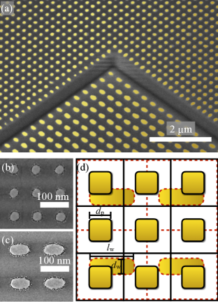
In order to explore the effect of reflection paths in a real sample we designed and fabricated a metasurface stack consisting of two metasurfaces separated by a glass spacer. The upper or front facing metasurface is comprised of a 2D-array of gold nano-patches with period , average diameter , and height . The lower metasurface comprises a 2D-array of gold nano-wires with period , average lateral dimensions and , and height . Both metasurfaces were embedded in a glass matrix. Fig. 1 (a) shows a scanning electron beam (SEM) image of the sample.
Our fabrication technique employed structuring of a two layer resist via electron beam lithography, gold evaporation, and chemical lift-off. To obtain reference fields of each metasurface layer in the stack, we fabricated each on two separate fields: the stack itself (fig. 1 (a)) and a single layer of the respective metasurface (figs. 1 (b), (c)), resulting in a total of three samples. After fabricating the first metasurface with this technique, we added a spacer layer using spin-on glass (Futurrex IC1-200) and etched it to the desired thickness of . We then fabricated the upper layer metasurface using the same approach as for the lower one. Finally, we added a fused silica cladding layer of thickness by chemical vapor deposition.
IV.2 Semi-analytic modeling
We specifically chose patches and wires for their different symmetry, i.e. and , respectively. This gave us the opportunity to analyze the effect of each reflection path on the anisotropic response of the stack, being itself anisotropic with an overall symmetry. Furthermore, the periods of the arrays have a ratio of , creating a super-period of the stacked unit cells, as shown in fig. 1 (d). Modelling such super-periodic systems usually demands rigorous simulations with high computational effort [33]. In our case, however, the spacer thickness of permits applying the FMA, enabling a more efficient semi-analytic approach [33, 36].
We developed a model of the stack utilizing the semi-analytic-stacking algorithm (SASA) presented in [33, 36], which separates the problem into an analytic and a numeric part using S-matrices as described above. Berkhout and Koenderink [31] recently published a comparable approach using transfer matrices. Since we deal with S-matrices and aim to analyze the properties of each scattering channel, SASA is the more suitable choice.
First, using the Fourier modal method (FMM) [45, 56], we computed the two metasurfaces’ S-matrices ( for the patches and for the wires) separately for wavelengths ranging from to , while assuming symmetric embedding. Ellipsometric measurements of the materials produced by our fabrication processes supplied refractive index data [57]. Next, all homogeneous dielectric layers, i.e. the spacer, , and the cladding covering the stack, , were calculated analytically as propagators of phases [36]. Furthermore, we applied Fresnel equations for the interface S-matrix at the top of the stack, representing the glass-air interface of the cladding [33]. In terms of S-matrices the stack is then given by the cascaded star product
| (12) |
The glass wafer at the base of the sample can be considered as a glass half-space with respect to the stack and needs no representation by an S-matrix.
IV.3 Experimental validation
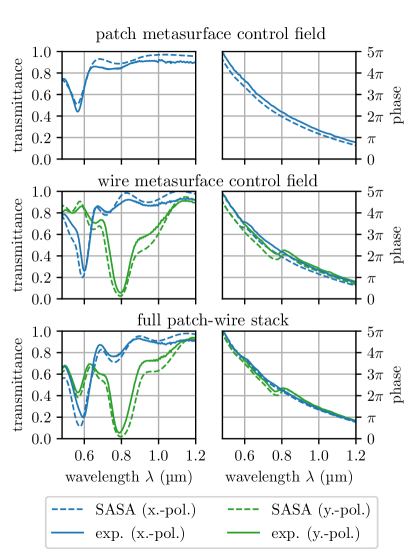
To ensure the validity of our SASA model we compared it against experimental results. Using a custom-built in-house characterization setup [58, 59], we performed interferometric measurements of both the single layer fields and the full stack, simultaneously measuring transmittance and phase in x- and y-polarization. Fig. 2 shows very good agreement between the SASA model and the measurement, both for transmittance and phase.
The isotropic patch-metasurface of the upper layer exhibits a single resonance at approximately . On the other hand, the symmetric wire-metasurface of the lower layer shows two distinct resonances for different polarization at approximately and . The isotropic resonance overlaps with polarization sensitive resonances in the stacked configuration. For x-polarization this results in a broader and more prominent resonance at . However, in y-polarization the transmittance now shows two resonances. The phase is mainly determined by the collective heights of spacer and cladding. Phase jumps at the resonance positions of the single layers combine in the stack.
IV.4 Reflection path extraction
Having a valid model of the patch-wire stack we now move on to the extraction and analysis of its reflection paths. For brevity, we focus on forward transmission, i.e. propagation from top to bottom of the stack. The S-matrices of the homogeneous layers and are diagonal matrices with exponential propagation phase terms of the form ). Here, is the refractive index of the homogeneous medium, its thickness, and the vacuum wavenumber. With this we can write the geometric expansion of the patch-wire stack up to order as
| (13) |
where and denote the propagation coefficients of spacer and cladding, respectively. Reflection and transmission at the glass-air interface of the cladding are given by the Jones matrices and of the interface S-matrix [36].
This can be interpreted as follows. The transmission matrices and are the input and output ports of the stack. Reading eq. (13) from right to left, the first parenthesis gives all interactions between the patch-metasurfaces and the top interface of the stack. The second parenthesis includes all interactions between the wire-metasurface and the patch-metasurface. The summations contribute all recurring reflections between those layers. In this context, the multi-index reflection matrix bundles all recurring reflections between the top and the spacer of the stack in backward direction.
With the notation from eqs. (9) and (10) as well as using eq. (8) to calculate the reflection matrices in (13), we can formulate the explicit expressions of the physical reflection paths in eq. (13). In -polarization the transmission coefficients of zeroth order and the first three paths contained at first order () read as
| (14) | ||||
| (15) | ||||
| (16) | ||||
| (17) |
where we omitted the superscripts f and b for the sake of readability. Above, eqs. (15) through (17) show the coefficients of the paths emerging at first order, such that . The graphical representation of these coefficients in fig. 3 shows the paths in the context of the fabricated stack. Whereas the leading transmissive term expresses propagation straight through the stack, the first order paths include different combinations of recurring reflections.
The leading transmissive term is composed of the single layer transmission coefficients, with and imposing an additional phase shift. Both the isotropic patch-metasurface and the anisotropic wire-metasurface contribute equally to the combined transmission coefficient. At higher orders each reflection path shows different compositions of the isotropic and anisotropic contributions. Therefore, they add different degrees of anisotropy to the interferometric part of the stack’s transmission.
Inputting the SASA results into eqs. (10) and (13) we computed both the truncated series and the coefficients of the patch-wire stack numerically. To see how the series converges we truncated this time at second order (). Fig. 4 shows amplitude and phase of both sets of coefficients, and , both for x- and y-polarized light. Looking at the set of truncated coefficients (figs. 4 (a), (b)) we see that the series already approximates the amplitude of the full result well at 1st order. The phase, however, seems to be insensitive to the expansion. But this is no surprise since the phase is mainly determined by the propagation lengths in the stack and its resonances. Any extra phase vanishes due to interference. In contrast, the set of coefficients contributing to each order (figs. 4 (c), (d)) shows the accumulated phase of the taken paths, albeit without interference. Here, we see that the metasurfaces’ resonances manifest themselves in the amplitude of the 1st order contribution.
IV.5 Virtual polarization states
The discussion above showed how and to what degree different orders of reflection paths contribute to the overall stack response. Now, we can pose the question: what other physical insights can we deduce from the properties of reflection paths? Indeed, with an anisotropic stack at hand we can gauge the degree of anisotropy at different expansion orders.
By calculating the ellipticity of the sets of coefficients from fig. 4 we can compare the stack’s overall anisotropic response to that of each expansion order. From the results shown in fig. 5 (a) we can conclude that for x-polarization the stack’s response is mostly linearly polarized with a slight deviation around the resonance wavelength at . In y-polarization (fig. 5 (b)) elliptical polarization is produced around the stronger resonance at . As before, the geometric series converges already at 1st order.
The ellipticity of the individual reflection paths shows more complex behavior (figs. 5 (c), (d)). For instance, at first order in x-polarization a circular polarization state emerges at a wavelength of (fig. 5 (c)). We term such states virtual polarization states since they interfere with other paths and produce only low amplitudes. This demonstrates that the reflection paths of the patch-wire stack are anisotropic to varying degree. Even though it is small, they have a distinguishable influence on the stacks overall anisotropic response.
V Conclusions
In conclusion, we revealed the existence of virtual polarization states of a metasurface stack by analyzing the reflection paths of its internal modal interactions. Our approach was motivated by the treatment of electron scattering in mesoscopic electron transport using a multiport formalism. This concept is mathematically equivalent to the scattering matrix formalism we employed. Based on this conceptual overlapp we could adopt the analogy of Feynman paths and electron scattering paths to the scattering problem in stacked metasurfaces.
In this work we applied a geometric expansion to the S-matrix of an anisotropic patch-wire metasurface stack under the necessary condition of the FMA. We demonstrated that its transmission could be separated into a leading transmissive term and a series of interferometric terms, representing the reflection paths of the stack. By truncating the series and analyzing its constituent coefficients, we revealed the properties of paths of different order as well as their influence on the overall response.
The knowledge of reflection paths could prove useful in understanding the interaction of more complex stacks with multiple diffraction channels [32]. Furthermore, we believe that the concept of Feynman paths could help in developing semi-analytic models of near-field interactions of complex nano-structures which can be challenging to comprehend, even numerically [58, 11, 19].
Finally, we would like to emphasize the benefit of adopting concepts from different fields of physics and identifying their similarities in order to gain more insight on certain physical phenomena.
Acknowledgements.
We would like to thank Prof. Asger Mortensen for discussions leading to the idea of exploiting methods from electronic transport in mesoscopic systems. Furthermore, we would like to thank Prof. Yuri Kivshar for discussions on the scope of the paper. Thanks are also due for or fabrication team, Michael Steinert, Waltraut Gräf, Holger Schmidt, and Daniel Voigt, for their support in the experimental realization of the patch-wire stack. We gratefully acknowledge financial support by the German Federal Ministry of Education and Research in the program ’Zwanzig20 - Partnership for Innovation’ as part of the research alliance 3Dsensation (grant numbers 03ZZ0466, 03ZZ0471D, and 03ZZ0451 as well as 03Z1H534). Furthermore, we are grateful for funding by the ’Deutsche Forschungsgemeinschaft’ (DFG, German Research Foundation) – Project-ID 278747906 and by the European Community within H2020 – Project-ID 899673 (METAFAST).References
- Rubin et al. [2019] N. A. Rubin, G. D’Aversa, P. Chevalier, Z. Shi, W. T. Chen, and F. Capasso, Matrix Fourier optics enables a compact full-Stokes polarization camera, Science 365, eaax1839 (2019).
- Karalis and Joannopoulos [2019] A. Karalis and J. D. Joannopoulos, Plasmonic Metasurface “Bullets” and other “Moving Objects”: Spatiotemporal Dispersion Cancellation for Linear Passive Subwavelength Slow Light, Physical Review Letters 123, 067403 (2019).
- Colburn et al. [2018] S. Colburn, A. Zhan, and A. Majumdar, Metasurface optics for full-color computational imaging, Science Advances 4, 1 (2018).
- Zhu et al. [2017] X. Zhu, W. Yan, U. Levy, N. A. Mortensen, and A. Kristensen, Resonant laser printing of structural colors on high-index dielectric metasurfaces, Science Advances 3, 1 (2017).
- Hentschel et al. [2017] M. Hentschel, M. Schäferling, X. Duan, H. Giessen, and N. Liu, Chiral plasmonics, Science Advances 3, e1602735 (2017).
- Aieta et al. [2015] F. Aieta, M. A. Kats, P. Genevet, and F. Capasso, Multiwavelength achromatic metasurfaces by dispersive phase compensation, Science 347, 1342 (2015), arXiv:1411.3966 .
- Lin et al. [2014] D. Lin, P. Fan, E. Hasman, and M. L. Brongersma, Dielectric gradient metasurface optical elements, Science 345, 298 (2014).
- Genevet et al. [2017] P. Genevet, F. Capasso, F. Aieta, M. Khorasaninejad, and R. Devlin, Recent advances in planar optics: from plasmonic to dielectric metasurfaces, Optica 4, 139 (2017).
- Tretyakov [2017] S. A. Tretyakov, A personal view on the origins and developments of the metamaterial concept, Journal of Optics 19, 013002 (2017).
- Staude et al. [2019] I. Staude, T. Pertsch, and Y. S. Kivshar, All-Dielectric Resonant Meta-Optics Lightens up, ACS Photonics 10.1021/acsphotonics.8b01326 (2019).
- Kenanakis et al. [2015] G. Kenanakis, A. Xomalis, A. Selimis, M. Vamvakaki, M. Farsari, M. Kafesaki, C. M. Soukoulis, and E. N. Economou, Three-Dimensional Infrared Metamaterial with Asymmetric Transmission, ACS Photonics 2, 287 (2015).
- Liu and Lalanne [2010] H. Liu and P. Lalanne, Comprehensive microscopic model of the extraordinary optical transmission, Journal of the Optical Society of America A 27, 2542 (2010).
- Poddubny et al. [2016] A. N. Poddubny, I. V. Iorsh, and A. A. Sukhorukov, Generation of Photon-Plasmon Quantum States in Nonlinear Hyperbolic Metamaterials, Physical Review Letters 117, 123901 (2016).
- Limonov et al. [2017] M. F. Limonov, M. V. Rybin, A. N. Poddubny, and Y. S. Kivshar, Fano resonances in photonics, Nature Photonics 11, 543 (2017).
- Wang et al. [2018] K. Wang, J. G. Titchener, S. S. Kruk, L. Xu, H.-p. Chung, M. Parry, I. I. Kravchenko, Y.-h. Chen, A. S. Solntsev, Y. S. Kivshar, D. N. Neshev, and A. A. Sukhorukov, Quantum metasurface for multiphoton interference and state reconstruction, Science 361, 1104 (2018).
- Wang et al. [2019] K. Wang, S. V. Suchkov, J. G. Titchener, A. Szameit, and A. A. Sukhorukov, Inline detection and reconstruction of multiphoton quantum states, Optica 6, 41 (2019).
- Yesilkoy et al. [2019] F. Yesilkoy, E. R. Arvelo, Y. Jahani, M. Liu, A. Tittl, V. Cevher, Y. Kivshar, and H. Altug, Ultrasensitive hyperspectral imaging and biodetection enabled by dielectric metasurfaces, Nature Photonics 13, 390 (2019).
- Do et al. [2013] Y. S. Do, J. H. Park, B. Y. Hwang, S.-M. Lee, B.-K. Ju, and K. C. Choi, Color Filters: Plasmonic Color Filter and its Fabrication for Large-Area Applications, Advanced Optical Materials 1, 109 (2013).
- Forouzmand and Mosallaei [2018] A. Forouzmand and H. Mosallaei, Composite Multilayer Shared-Aperture Nanostructures: A Functional Multispectral Control, ACS Photonics 5, 1427 (2018).
- Jin et al. [2018] L. Jin, Z. Dong, S. Mei, Y. F. Yu, Z. Wei, Z. Pan, S. D. Rezaei, X. Li, A. I. Kuznetsov, Y. S. Kivshar, J. K. W. Yang, and C.-w. Qiu, Noninterleaved Metasurface for (2 6 -1) Spin- and Wavelength-Encoded Holograms, Nano Letters 18, 8016 (2018).
- Li et al. [2016] X. Li, L. Chen, Y. Li, X. Zhang, M. Pu, Z. Zhao, X. Ma, Y. Wang, M. Hong, and X. Luo, Multicolor 3D meta-holography by broadband plasmonic modulation, Science Advances 2, e1601102 (2016).
- Zhou et al. [2018] Y. Zhou, I. I. Kravchenko, H. Wang, J. R. Nolen, G. Gu, and J. Valentine, Multilayer Noninteracting Dielectric Metasurfaces for Multiwavelength Metaoptics, Nano Letters 18, 7529 (2018).
- Arbabi et al. [2016] A. Arbabi, E. Arbabi, S. M. Kamali, Y. Horie, S. Han, and A. Faraon, Miniature optical planar camera based on a wide-angle metasurface doublet corrected for monochromatic aberrations, Nature Communications 7, 13682 (2016), arXiv:arXiv:1604.06160v2 .
- Kuznetsov et al. [2015] S. a. Kuznetsov, M. a. Astafev, M. Beruete, and M. Navarro-Cía, Planar Holographic Metasurfaces for Terahertz Focusing, Scientific Reports 5, 7738 (2015).
- Hsu et al. [2013] C. W. Hsu, B. Zhen, J. Lee, S.-l. Chua, S. G. Johnson, J. D. Joannopoulos, and M. Soljačić, Observation of trapped light within the radiation continuum, Nature 499, 188 (2013).
- Monticone and Alù [2014] F. Monticone and A. Alù, Embedded Photonic Eigenvalues in 3D Nanostructures, Physical Review Letters 112, 213903 (2014).
- Hsu et al. [2016] C. W. Hsu, B. Zhen, A. D. Stone, J. D. Joannopoulos, and M. Soljačić, Bound states in the continuum, Nature Reviews Materials 1, 16048 (2016).
- Cerjan et al. [2019] A. Cerjan, C. W. Hsu, and M. C. Rechtsman, Bound States in the Continuum through Environmental Design, Physical Review Letters 123, 023902 (2019).
- Vázquez-Guardado and Chanda [2018] A. Vázquez-Guardado and D. Chanda, Superchiral Light Generation on Degenerate Achiral Surfaces, Physical Review Letters 120, 137601 (2018).
- Duggan et al. [2019] R. Duggan, J. del Pino, E. Verhagen, and A. Alù, Optomechanically Induced Birefringence and Optomechanically Induced Faraday Effect, Physical Review Letters 123, 023602 (2019), arXiv:1904.05463 .
- Berkhout and Koenderink [2020] A. Berkhout and A. F. Koenderink, A simple transfer-matrix model for metasurface multilayer systems, Nanophotonics 0, 20200212 (2020).
- Chen et al. [2019] S. Chen, Y. Zhang, Z. Li, H. Cheng, and J. Tian, Empowered Layer Effects and Prominent Properties in Few‐Layer Metasurfaces, Advanced Optical Materials 1801477, 1801477 (2019).
- Menzel et al. [2016] C. Menzel, J. Sperrhake, and T. Pertsch, Efficient treatment of stacked metasurfaces for optimizing and enhancing the range of accessible optical functionalities, Physical Review A 93, 063832 (2016), arXiv:1511.09239 .
- Zhao et al. [2012] Y. Zhao, M. Belkin, and A. Alù, Twisted optical metamaterials for planarized ultrathin broadband circular polarizers, Nature Communications 3, 870 (2012).
- Lin et al. [2019] H. Lin, B. C. P. Sturmberg, K.-T. Lin, Y. Yang, X. Zheng, T. K. Chong, C. M. de Sterke, and B. Jia, A 90-nm-thick graphene metamaterial for strong and extremely broadband absorption of unpolarized light, Nature Photonics 13, 270 (2019).
- Sperrhake et al. [2019] J. Sperrhake, M. Decker, M. Falkner, S. Fasold, T. Kaiser, I. Staude, and T. Pertsch, Analyzing the polarization response of a chiral metasurface stack by semi-analytic modeling, Optics Express 27, 1236 (2019).
- Yun et al. [2018] J.-G. Yun, J. Sung, S.-J. Kim, and B. Lee, Simultaneous control of polarization and amplitude over broad bandwidth using multi-layered anisotropic metasurfaces, Optics Express 26, 29826 (2018).
- Datta [1995] S. Datta, Electronic transport in mesoscopic systems, 1st ed. (Cambridge University Press, 1995) p. 393.
- Robinson and Jeffery [1995] S. J. Robinson and M. Jeffery, Conductance fluctuations in mesoscopic three-dimensional multiply connected normal-wire networks, Physical Review B 51, 16807 (1995).
- Büttiker [1986] M. Büttiker, Four-Terminal Phase-Coherent Conductance, Physical Review Letters 57, 1761 (1986).
- Nazarov [2015] Y. V. Nazarov, Block-determinant formalism for an action of a multi-terminal scatterer, Physica E: Low-dimensional Systems and Nanostructures 74, 561 (2015).
- Shavit and Oreg [2019] G. Shavit and Y. Oreg, Fractional Conductance in Strongly Interacting 1D Systems, Physical Review Letters 123, 036803 (2019).
- Texier and Montambaux [2016] C. Texier and G. Montambaux, Reprint of: Four-terminal resistances in mesoscopic networks of metallic wires: Weak localisation and correlations, Physica E: Low-dimensional Systems and Nanostructures 82, 272 (2016).
- Li [1994] L. Li, Bremmer series, R-matrix propagation algorithm, and numerical modeling of diffraction gratings, Journal of the Optical Society of America A 11, 2829 (1994).
- Li [1996] L. Li, Formulation and comparison of two recursive matrix algorithms for modeling layered diffraction gratings, Journal of the Optical Society of America A 13, 1024 (1996).
- Buttiker [1988] M. Buttiker, Symmetry of electrical conduction, IBM Journal of Research and Development 32, 317 (1988).
- Büttiker et al. [1985] M. Büttiker, Y. Imry, R. Landauer, and S. Pinhas, Generalized many-channel conductance formula with application to small rings, Physical Review B 31, 6207 (1985).
- Simovski [2007] C. R. Simovski, Bloch material parameters of magneto-dielectric metamaterials and the concept of Bloch lattices, Metamaterials 1, 62 (2007).
- Simovski et al. [2007] C. R. Simovski, S. A. Tretyakov, and ., Local constitutive parameters of metamaterials from an effective-medium perspective, Physical Review B 75, 195111 (2007).
- Simovski [2009] C. R. Simovski, Material parameters of metamaterials (a Review), Optics and Spectroscopy 107, 726 (2009).
- Menzel et al. [2010] C. Menzel, C. Rockstuhl, and F. Lederer, Advanced Jones calculus for the classification of periodic metamaterials, Physical Review A - Atomic, Molecular, and Optical Physics 82, 1 (2010), arXiv:1008.4117 .
- Redheffer [1960] R. M. Redheffer, On a Certain Linear Fractional Transformation, Journal of Mathematics and Physics 39, 269 (1960).
- Note [1] If it is invertible and its block-matrix elements do not take values . This is usually the case for physical systems including absorption.
- Bremmer [1951] H. Bremmer, The W.K.B. approximation as the first term of a geometric-optical series, Communications on Pure and Applied Mathematics 4, 105 (1951).
- Note [2] See supplementary material for information on truncation.
- Noponen and Turunen [1994] E. Noponen and J. Turunen, Eigenmode method for electromagnetic synthesis of diffractive elements with three-dimensional profiles, Journal of the Optical Society of America A 11, 2494 (1994).
- Dietrich et al. [2012] K. Dietrich, D. Lehr, C. Helgert, A. Tünnermann, and E.-B. Kley, Circular Dichroism from Chiral Nanomaterial Fabricated by On-Edge Lithography, Advanced Materials 24, OP321 (2012).
- Helgert et al. [2011] C. Helgert, E. Pshenay-Severin, M. Falkner, C. Menzel, C. Rockstuhl, E.-B. Kley, A. Tünnermann, F. Lederer, and T. Pertsch, Chiral Metamaterial Composed of Three-Dimensional Plasmonic Nanostructures, Nano Letters 11, 4400 (2011).
- Pshenay-Severin et al. [2014] E. Pshenay-Severin, M. Falkner, C. Helgert, and T. Pertsch, Ultra broadband phase measurements on nanostructured metasurfaces, Applied Physics Letters 104, 221906 (2014).