A General Topological Network Criterion for Exploring the Structure of Icy Nanoribbons and Monolayers
Department of Chemical Engineering
Indian Institute of Technology Kanpur
amritag@iitk.ac.in
&
Department of Chemical Engineering
Indian Institute of Technology Kanpur
jayantks@iitk.ac.in
Abstract
We develop intuitive metrics for quantifying complex nucleating systems under confinement. These are shown to arise naturally from the analysis of the topological ring network, and are amenable for use as order parameters for such systems. Drawing inspiration from qualitative visual inspection, we introduce a general topological criterion for elucidating the ordered structures of confined water, using a graph theoretic approach. Our criterion is based on primitive rings, and reinterprets the hydrogen-bond-network in terms of these primitives. This approach has no a priori assumptions, except the hydrogen bond definition, and may be used as an exploratory tool for the automated discovery of new ordered phases. We demonstrate the versatility of our criterion by applying it to analyse well-known monolayer ices. Our methodology is then extended to identify the building blocks of one-dimensional -sided prismatic nanoribbon ices.
Keywords nucleation, structure-determination, topological-order-parameter, confined-water, nanoribbon-ices
1 Introduction
Confinement is known to cause deviations from bulk system properties [1, 2, 3, 4], imparting unique complexities to the structure determination of icy confined water. The structure and phase behaviour of quintessential confined systems, like that of two-dimensional monolayer and one-dimensional nanoribbons are of enormous theoretical[5, 4, 6] and experimental interest[7, 8]. However, well-defined simulation methodologies and methods of analysis for bulk systems like the mean squared displacement (MSD), often used as a broad indicator of phase transitions, may be unreliable for constrained ice systems. The reasons are two-fold: confined water often exhibits continuous freezing transitions [9, 10, 11], and the mobility of water layers close to the confining sheet is lower than that of intermediate layers [12, 13]. Parameters engineered to characterize phase transitions in simpler Lennard-Jones systems, inspired by the MSD, are not universally valid. For example, the Lindemann parameter, which has been used for melting studies[14, 15], fails for confined systems with attractive pores due to instabilities in the MSD [16]. Structure determination techniques, which are accurate for bulk water, are often intractable for nucleating water systems under confinement, as the hydrogen-bonding network (HBN) is significantly influenced by the confining wall. Compared to bulk water, water under nanoscale confinement shows considerable polymorphic diversity [17].
Visual inspection of the HBN, paired with the angle distribution, has been used in the literature for the analysis of confined water systems. Such techniques are often used for qualitative analyses [10, 11, 18, 5, 19] but are unable to describe the structures quantitively. Voronoi tessellation [20] has been previously used to quantify the structures of two-dimensional confined ice systems. The bond orientational parameter has also been used for distinguishing the degree of square and hexagonal order in ice [21]. However, the bond orientational parameter has implicit a priori assumptions of the ice structures formed, and cannot be used as an exploratory tool. Moreover, none of these parameters has been successfully applied to one-dimensional nanoribbon ices, although axial and angular order parameters for distinguishing between square and pentagonal ice nanotubes have been used [1]. There is no single straightforward classification technique for confined ordered ice-like water that minimizes human involvement and assumptions, and emphasizes automated, reproducible, quantifiable structural elucidation.
Determining the connectivity of an ordered phase by using the primitive rings formed is a well-established technique of identification [22, 23, 24, 25, 26, 27]. Ic (cubic ice) and Ih (hexagonal ice) are ice phases, which are similar enough that their structural differences are not trivially discernible by casual inspection. A robust and intuitive classification of the building-blocks of Ic and Ih, based on primitive ring connectivity, has been formulated [28] and used for homogenous and heterogenous bulk nucleation [29, 30, 31]. However, these topological network connectivity analyses, like other popular analyses including spherical harmonics based methods, suffer from a common shortcoming. All such classification techniques use a fixed-distance cutoff, after which further reductions or criteria are applied. These techniques work on the assumption that distance-based information is nearly equivalent to the HBN information. This implicit assumption is known to be valid for bulk systems of deeply supercooled water [32]. Thus, for such systems, the distance-based cutoff, corresponding to the first nearest-neighbor shell of the oxygen atoms (first minimum of the O-O radial distribution function) is a close approximation of the HBN, with negligible overcounting [28].
The scenario is more complex for confined systems. Confined systems show a variety of ordered phases at temperatures much higher than the freezing point of the bulk liquid. Experimental results have predicted substantial temperature elevations of the freezing transition for water constrained within isolated carbon nanotubes, compared to the bulk phase [8]. Simulations have also shown that certain confined systems exhibit a freezing point as high as [33]. In particular, at high pressures or under strong confinement, we show that a fixed distance-cutoff creates connections between molecules which are not actually part of the HBN. A naive application of a topological network criterion based on a fixed distance cutoff, thus, necessarily fails by creating extraneous connections.
We summarize the main practical challenges of confined ice structure determination as follows:
-
1.
Confined water has a high number of possible polymorphs of quasi-one and two-dimensional ice. These manifest even at elevated temperatures compared to the bulk. The ordered structures are highly sensitive to the geometry of the confining surface and hydrophobicity.
-
2.
A molecule in confined water may not actually form a hydrogen-bond with every one of its nearest neighbours. This is because molecules forced within the first nearest-neighbour shell under the effect of confinement or high pressure may not fulfil the additional strict criterion of hydrogen bond formation. We show that not accounting for the hydrogen bonds can cause significant mis-identification of ice.
In the following sections, we introduce a robust topological network criterion for quantitatively and qualitatively classifying quasi-one-dimensional and two-dimensional ice structures, specifically adapted for confined systems. We demonstrate the generality of our method by using it to identify structures of well-known one-dimensional nanoribbons and two-dimensional monolayer ices. We have also formulated a prism identification scheme for identifying the constituent building blocks of -gonal one-dimensional ice. Our graph-theoretic network criterion leads to intuitive metrics for quantifying network structures, including the projected area, the occupied volume, and other similar topological features, which shed light on simulation results. We prove the efficacy of such analysis techniques for systems at higher temperature phases and transitions of monolayer ice within a graphite nanochannel. We show how our topological network parameter may be used for exploratory studies of entirely new systems. Our order parameter as described, is based on purely topological features, and makes no assumptions of the regularity of the local environment or symmetry factors, instead relying solely on the description of the hydrogen bonds.
2 Theory and Methods
2.1 Topological Network Criterion
Visual inspection of confined systems (Figure 1(a)) gravitates towards the identification of polygons. To this end, we have shown that the composition of the HBN, in terms of -membered rings may be used for classification purposes. Our definition of a ring is similar to that in the literature [24, 28]. We define a ring as the largest polygon that can be formed from oxygen atoms of hydrogen-bonded molecules, such that it cannot be broken into smaller constituent rings. This is, in essence, the mathematical description of a primitive ring, using King’s shortest path criterion [34].
Here, we outline the methodology by applying it to fMSI (flat Monolayer Square Ice) formed within a graphene nanochannel [18]. In previous treatments of bulk ice and supercooled water, primitive ring analyses have been implemented using a fixed-distance cutoff [24, 28]. However, we demonstrate that a naive application of primitive ring analysis using a fixed-distance cutoff introduces severe error, necessitating modifications of the methodology for confined systems. The ring network formed using a fixed-distance cutoff has been depicted in Figure 1(b). Figure 1(c) shows extraneous bonds, coloured in red and blue, caused by using primitive rings without accounting for the HBN, shown here in black. This visual representation shows how the HBN does not coincide with the ring network formed using a fixed-distance cutoff.
Our topological network criterion incorporates the information of the HBN, thus eliminating superfluous bonds with high accuracy. Figure 1 depicts the various intermediate stages in the classification of fMSI formed within the graphene nano-capillary. Our methodology is as follows.
First, all molecules connected by hydrogen bonds are identified using a strict geometric criterion. Figure 1(a) shows the HBN for fMSI, with connections between oxygen molecules which are hydrogen-bonded. In this particular treatment, no difference is made between donor and acceptor molecules. We define an oxygen atom to be hydrogen-bonded to a hydrogen atom if the angle between the O–O and O-H vectors is less than 30 degrees, and if the distance between the possible donor oxygen and acceptor hydrogen is less than [35].
Following this, we determine all possible primitive rings, from to . In this case, the number of primitive rings for is negligible. A distance cutoff of is used, sufficient to encompass all first-neighbour shell molecules. However, there are still several extraneous bonds, clearly visible in Figure 1(c).
Next, we eliminate all primitive rings with connections between molecules which are not hydrogen-bonded, using the previously determined HBN information. By eliminating such non-hydrogen bonded rings, we obtain precise connectivity information while still closely approximating the HBN.
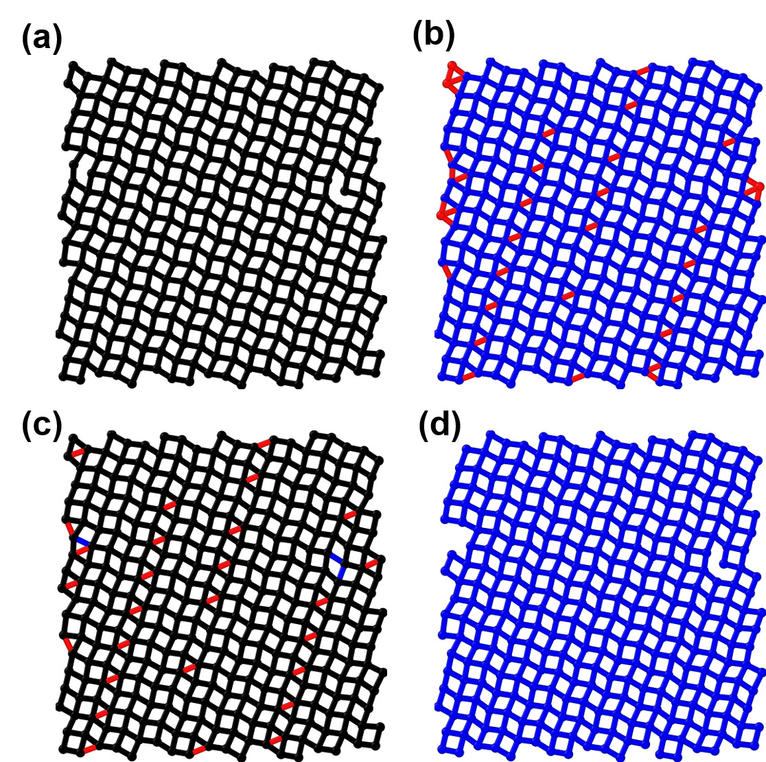
On eliminating extra bonds, the resultant ring network in Figure 1(d) almost perfectly coincides with the HBN in Figure 1(a). Our topological criterion correctly classifies the monolayer ice as being primarily square ice, and entirely eliminates the superfluous triangular phase.
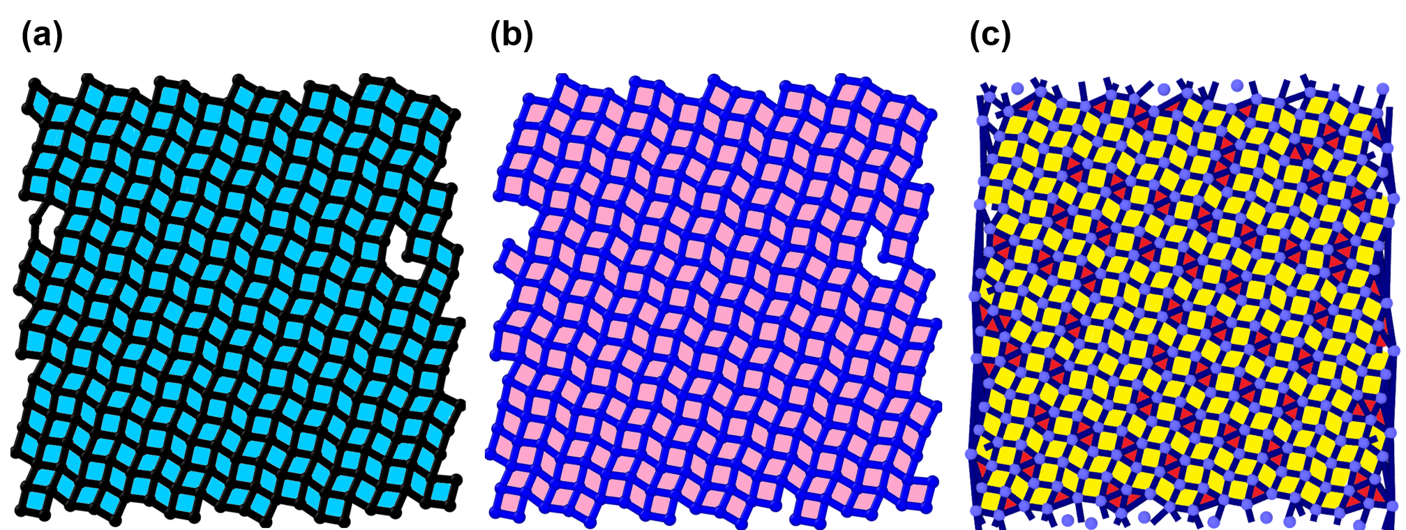
We have also tested our criterion by comparing its performance with that of Voronoi tessellation for the same fMSI phase described above, visually represented in Figure 2. The accuracy of any identification scheme can be assessed by judging the extent to which it reproduces the connectivity of the HBN. Even after applying face area and edge length thresholds, Voronoi tessellation creates several extra connections (Figure 2(c)). A perfectly accurate Voronoi diagram for this system would have had particles at the center of tetragonal Voronoi cells, corresponding to a coordination number of for each particle. In fact, the bond network generated by Voronoi tessellation in Figure 2(c) closely resembles the primitive ring network of Figure 1(b), for whose generation the hydrogen bonds were not considered and only a fixed-distance cutoff was used.
The advantage of our topological network criterion for structural determination is its unambiguous classification of the hydrogen-bonded ring network in terms of -membered primitive rings, even at ambient temperatures or strong confinement. It is also clearly evident that, under such conditions, a direct application of a primitive ring analysis using a fixed-distance cutoff introduces significant error. We observe that there is especially an increase in the erroneous identification of the triangular phase. Thus, keeping the non-hydrogen bonded extra connections (shown in Figure 1(b)) causes the incorrect identification of ice. We also note that the extra connections do not satisfy the Bernal-Fowler ice rules [36]. The fMSI, which is known to satisfy the ice-rules, visually indicates that the excess connections are not concurrent with the ice rules, while the reduced ring network in Figure 1(d) does not, at least, appear to violate the ice rules.
However, one caveat of eliminating rings is that, for example, one or two 3-membered primitive rings may be removed, whose sides could have formed a 4-membered ring which was not previously not considered to be primitive according to the fixed-distance criterion. Such rings form a negligible percentage of the whole, and are in the vicinity of point defects or the edges. In this specific case, three sets of pairs of triangles on the left edge and right edge were removed (visible when comparing Figures 1(b) and 1(d)). These actually form three 4-membered rings, which were also removed along with the extra bonds.
Depending on the number of nodes (three or four) in each ring, we note that the resulting topological network coincides with of the HBN.
The ring network obtained from our topological network criterion may be used as-is for monolayer ice identification. Using these hydrogen-bonded rings as a basis, we develop a prism identification algorithm for identifying -gonal prism blocks.
2.2 Prism Identification Algorithm
The structural building block of an -sided prism is an assortment of two basal -sided polygon planes, attached to each other by 4-membered lateral rings, as shown in Figure 3. First, hydrogen-bonded -membered rings are obtained according to the procedure outlined above in Section 2.1. These are subsequently used to identify -sided prism blocks.
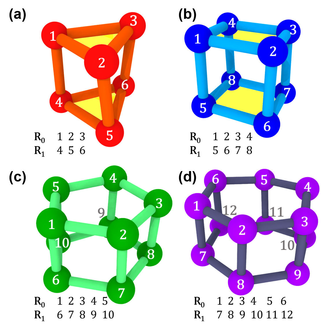
We use the following recipe for identifying -sided prisms. A pair of potential basal faces and is considered at a time. The 4-membered lateral faces connecting each pair of basal planes in a prism unit may be described solely by hydrogen bonds and do not need to be considered separately. The methodology is the same for any integral value of . Two candidate n-membered rings and are basal faces if the following conditions are true.
-
1.
. and should share no common nodes. They are only connected by hydrogen bonds.
-
2.
Every node in must be a nearest neighbour of a corresponding node in , such that every node in is hydrogen-bonded to exactly one node in . For example, a node in cannot be connected to both and in .
We apply our prism identification methodology to a zigzag SWNT (single-walled nanotube), with corresponding to a diameter of . The structure of the ice nanoribbon at , with a water occupancy of , is shown in Figure 4. At this temperature, the nanoribbon is mostly comprised of tetragonal prisms, one triangular prism, and unclassified polygons in the middle. The rings which were classified as belonging to no -sided prisms (unclassified) may denote the water phase, deformed prisms or a helical structure.
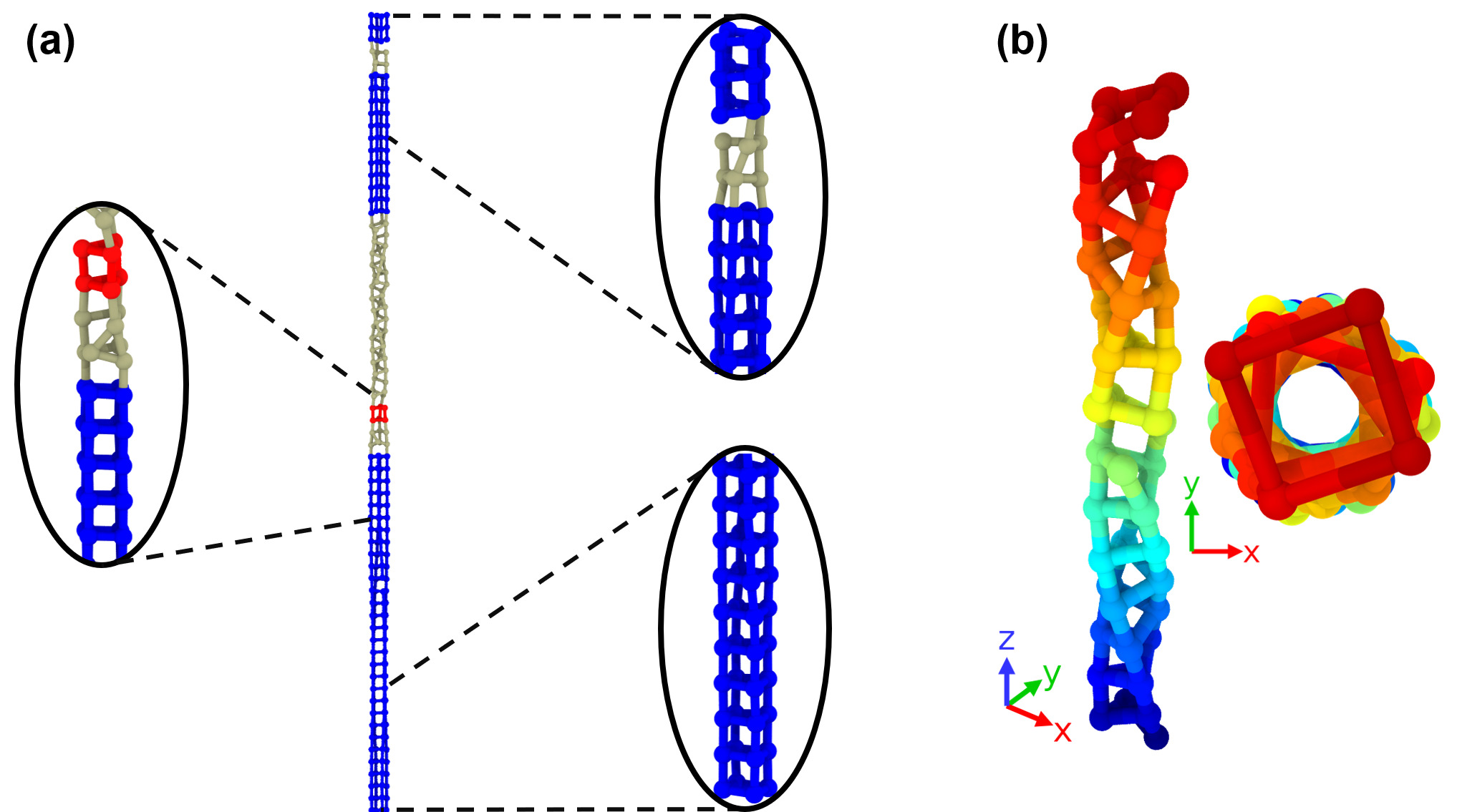
Specifically, the grey polygons in the top right inset of Figure 4 are deformed tetragonal prisms. We note also that the relatively twisted middle grey section of the nanoribbon has a hollow tube section, which indicates that it may be an ordered phase. It is also exclusively comprised of 4-membered polygons, coiled in a helical structure. The methodology for handling unknown nanoribbons with disparate structure compositions is given by the algorithm listed below:
-
1.
First, obtain the hydrogen-bonded -sided primitive rings for the system, such that .
-
2.
Apply the prism determination algorithm for every .
-
3.
The unclassified structures remaining may be water, deformed prisms, or part of an ordered ladder-like or helical structure. Liquid water tends to form disordered rings of widely varying , filling up the interior of the SWNT [4, 37]. If the unclassified structure does not fill the interior of the nanotube and exhibits a certain degree of order, it may be part of a helical structure, or a deformed prism, depending on the symmetry. A simple indication of order is the number and type of primitive rings comprising the unclassified sections. In the case of the nanoribbon in Figure 4, every unclassified molecule almost exclusively participates in only 4-membered rings. We also show, in subsequent sections, that our algorithm may be used to qualitatively describe the abrupt symmetry change in freezing icy nanoribbons.
2.3 Coverage Area Metric
The number of rings has been used as a qualitative metric in previous studies [23, 24, 26]. However, in our systems, 3-membered rings in the HBN are smaller in size than 4-membered rings, making the number of rings an unreliable descriptor (Figure 5).
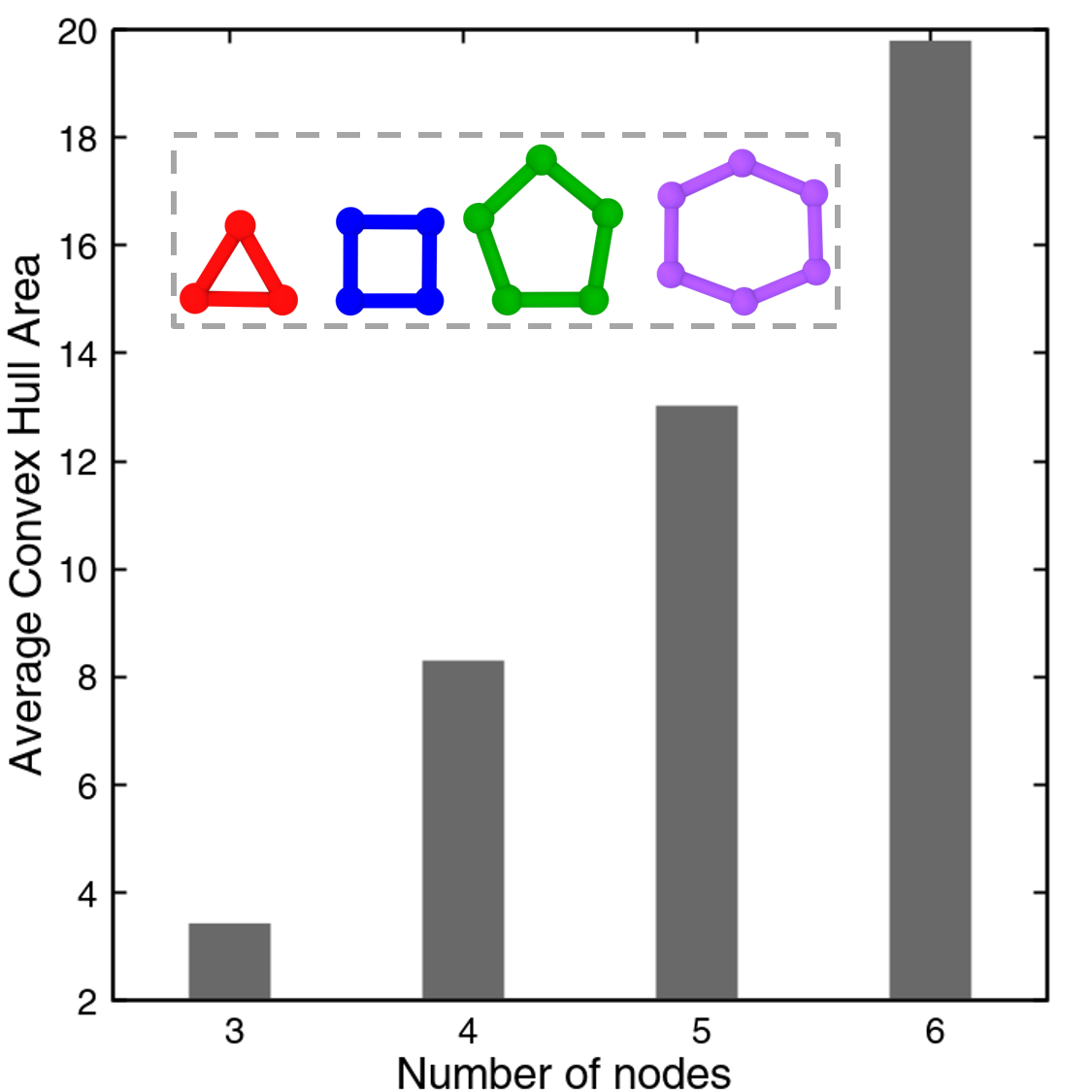
Intuitively, the area of each ring is a more qualitative metric for monolayer systems. In our monolayer simulation systems, water layers are formed in the plane. We define the -plane coverage area to be the projected area of each ring onto the plane. We normalize the coverage area by the theoretical maximum possible area of the ice, which, in the case of monolayer water, is the area of the confining sheet. The coverage area percentage is the percentage of the total area of the constraining sheet that is comprised of the projected area of -membered rings, where .
where is the projected area of the -membered ring, and is the total number of -membered rings.
The coverage area metric does not distinguish between small isolated clusters of -membered rings, and a contiguous connected cluster. It is possible to apply additional constraints for connected rings of certain types to identify ices like fMSI and pMSI (puckered Monolayer Square Ice), which are composed of a single type of ring. We have observed that thermal fluctuations momentarily fracture the ring network, which could disrupt the connectivity of large swathes of ordered rings. For the monolayer ices studied in this work, the coverage area percentage was found to describe phase transitions and relative proportions of -membered rings accurately.
2.4 Occupied Volume Metric
We formulate a qualitative volume-based metric to determine the relative proportions of -gonal prism structures within nanoribbons. Our prism determination algorithm produces pairs of -sided basal rings. We obtain the volume enclosed by the prism block by calculating the volume of the convex hull [38] formed by the basal ring vertices. For , the basal rings are perpendicular to the axis, but for , we only consider axial rings to prevent overcounting.
For every , the total volume of each -gonal prismatic phase is obtained by summing over the convex hull volumes of the prism blocks. We normalize this volume by the maximum possible volume, which is the occupied volume if an -sided prism were to fill the entire cylinder height. The maximum possible length of each edge is from solvation shell considerations. We have observed that the volume of each prism block for a particular is relatively constant, thermal fluctuations notwithstanding. Thus, for a particular prism phase, whose basal face has nodes, we can approximate the maximum possible filled volume by assuming that the SWNT is filled by a regular -gonal prism of height :
where is the length of the SWNT.
Thus, we define the occupied volume percentage for an -gonal prismatic phase as:
where the convex hull volume of the -gonal prism block, and is the total number of -gonal prism blocks.
The maximum possible volume which we have used as a normalizing factor varies for a particular . This is because the effective area of the basal ring is different for every , with trigonal basal rings occupying the least area. A consequence of this is that the sum of the occupied volume of various composite -gonal blocks is always less than the total volume. We prove in subsequent sections, that this occupied volume percentage is an accurate qualitative measure of phase transitions.
3 Simulation Details
We have studied the following systems: monolayer ice systems with explicit carbon atoms for simulating rigid (1) graphene layers, nanoribbon ices constrained by single-walled nanotubes (2) with smooth featureless walls, and (3) with explicit carbon atoms. The systems simulated are well-known in the literature and have thus been used for validation and benchmarking.
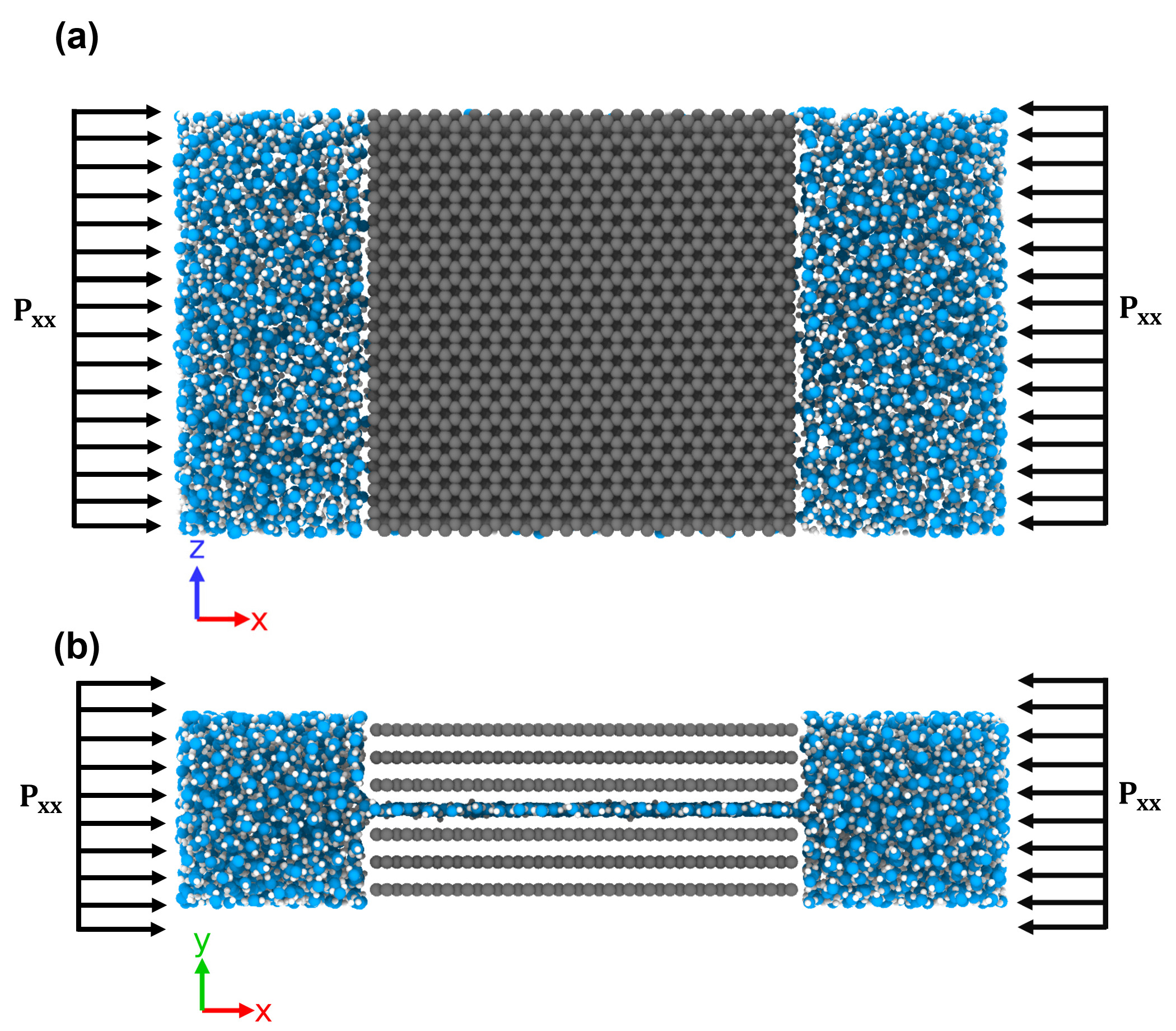
For the monolayer ice graphene water system, the simulation setup is similar to systems reported in the literature[18], shown in Figure 6. A nanochannel was created by introducing a gap width between a pair of three graphene sheets. Two water reservoirs, containing molecules, were placed on either side of the nanochannel thus formed. The dimensions of the sheets were in the and dimensions, respectively. We used center-to-center separation widths between the parallel diamond sheets of , which is sufficient to permit the formation of a single layer of water.
We have used LAMMPS [39] to run equilibrium Molecular Dynamics simulations. Lateral pressures were applied in the dimension. The MD simulations were performed in the isothermal-isobaric ensemble. The temperature and pressure were controlled by the Nose-Hoover thermostat and barostat, respectively. A timestep of was used for the Velocity-Verlet integration scheme. The particle-particle-particle mesh (PPPM) algorithm was used for computing the long-range interactions.
TIP4P/2005 [40] was used to model the water molecules in all the systems studied in this work. Among the commonly used rigid water models used for simulating confined systems, TIP4P/2005 performs reliably well compared to other popular rigid water models [21]. The sum of the interactions between the TIP4P/2005 molecules, and the external Lennard-Jones potential of interaction between the water molecules and the confining sheet yield the total potential of interaction.
In this work, we have used Lennard-Jones force-field parameters for the interactions between the oxygen atoms of water and the carbon atoms of graphene[41]. These parameters have been extensively used for graphite and water, accurately reproducing the contact angle of water on graphite [18, 10, 11, 20].
4 Results and Discussion
4.1 Freezing of an Ice Nanotube
We investigate the phase changes of water confined within a featureless SWNT, corresponding to a diameter of . When the temperature is lowered from , at a constant axial pressure of , an abrupt change in state from the liquid phase is observed at . The occupied volume percentage rises suddenly from to and for the pentagonal and hexagonal blocks respectively (Figure 7 (b)). No other -gonal prism structures are present.
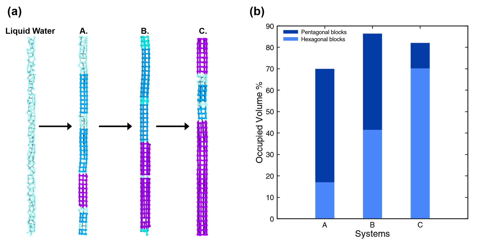
The prism determination criterion is also able to capture solid-to-solid phase transitions. Initially, at (System A. in Figure 7), a higher proportion of pentagonal prismatic ice is observed. However, we observe a gradual change of the pentagonal blocks to hexagonal blocks. After a simulation at the nanoribbon becomes almost exclusively comprised of hexagonal prism blocks.
4.2 Monolayer Within a Graphene Nanocapillary
Monolayer water exists in the form of fMSI when it is constrained between two graphene surfaces apart at and [10]. fMSI exhibits a first-order phase transition when it is subjected to superheating at a constant low lateral pressure () [20].
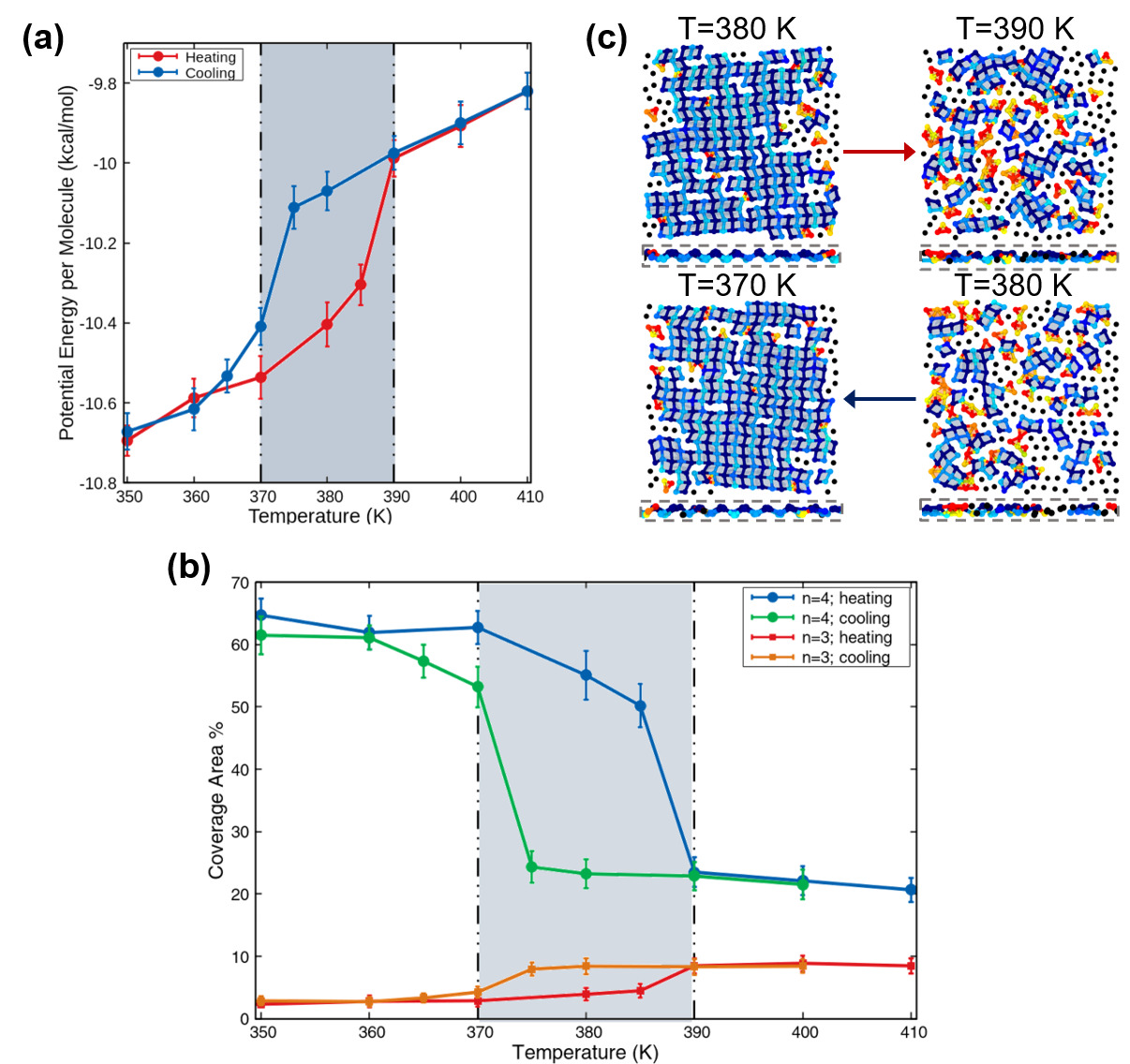
We have performed heating and cooling MD simulations of fMSI, using a simulation setup similar to those previously used in the literature [10, 20, 18]. Concomitant to the literature, we observe an abrupt increase in the potential energy per molecule of , corresponding to the disruption of the ordered HBN (Figure 8(a)).
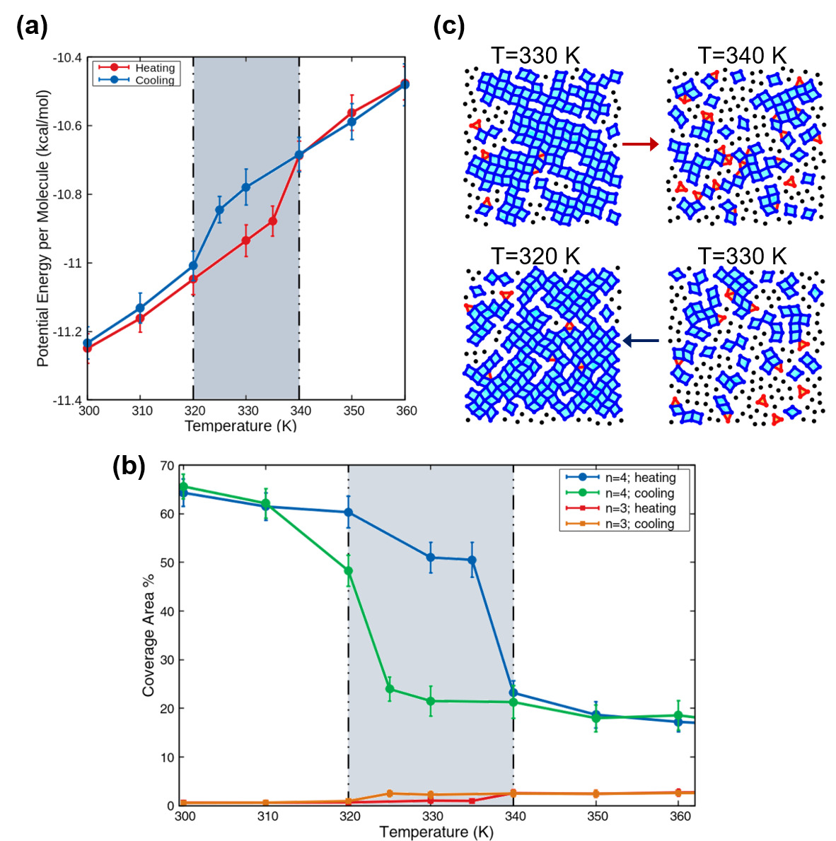
The plot of the coverage area percentage for 4-membered rings in Figure 8(b) shows a sharp decrease by when the temperature is increased to during the heating process. The coverage area percentage of 3-membered rings also changes during this phase transition. The disordered liquid network tends to have a relatively higher proportion of 3-membered rings (visually discernible in Figure 8(c)). However, fMSI has negligible proportions of 3-membered rings. When the monolayer is fMSI, the coverage area percentage of the 3-membered rings remains constant at . The hysteresis loop of the 3-membered rings echoes that of the 4-membered rings and the potential energy per molecule.
Figure 9(a) shows the potential energy per molecule change during the heating and cooling of pMSI, at a constant lateral pressure of . The coverage area percentage hysteresis loops mirror the hysteresis loop in the potential energy per molecule. The trends suggest that the phase transition is a first-order transition. The coverage area percentage change for the 3-membered rings (Figure 9(b)) is more significant for pMSI than for fMSI (Figure 8(b)).
Thus, the coverage area percentage is able to reproduce trends in the potential energy per molecule, showing a correspondingly large hysteresis loop.
5 Conclusions
In this work we have presented a general and extensible family of topological network criteria for the structural identification and analysis of quasi-one-dimensional and two-dimensional ices. The primitive rings, identified using a fixed-distance cutoff, are screened to obtain rings whose connections correspond to the HBN. An explicit accounting for the hydrogen bonds in confined ordered structures has been found to be necessary. The effects of confinement may force molecules to be clustered within a fixed distance cutoff corresponding to the first nearest-neighbour shell, but are additionally constrained by the viability of hydrogen bonds. We show how the reduction of non-hydrogen bonded connections is crucial to prevent mis-identification of fMSI. The primitive rings may be further analysed for further identification, or used as-is.
We use the primitive rings so obtained as a basis for an algorithm for identifying the building blocks of -sided prisms. Our prism identification algorithm classifies the -membered prism blocks which comprise single ice nanotubes (ICNs). Helical structures and deformed prisms are not identified by this particular recipe, but can still be distinguished from the liquid state by virtue of the number and type of the component primitive rings. We show how a modified projected area, the coverage area metric, may be used as an order parameter for investigating the phase transitions in monolayer water. The coverage area percentage for every , is a measure of the relative proportion of the -membered rings. We have also developed an analogous volume-based order parameter for ICN classification. In the same spirit as that of the coverage area metric, we reinterpret the topological features from a molecular simulation analysis perspective. The occupied volume percentage is calculated using the convex hull volumes of component prism blocks identified using the prism determination recipe. Both these metrics are able to qualitatively describe various pressure-induced and temperature-induced phase transitions.
The topological network criterion that forms the basis of these related methodologies is flexible and easily customizable, requiring no a priori assumptions beyond those for hydrogen bonds. We envisage that other interconnected networks, including multicomponent structures and solid-liquid interfaces may be probed using this general approach. The relative speed of the criterion presented here, and the scope for parallelization, make it possible to consider using it for on-the-fly calculations during simulation runs, at least for small systems.
We anticipate that these sets of techniques may have a wider applicability for other confined structures and geometries, especially those with mixed structures of unknown relative composition.
Acknowledgements
This work was supported by the Department of Science and Technology, Govt of India. Computational resources were provided by the HPC cluster of the Computer Center (CC), Indian Institute of Technology Kanpur.
References
- [1] Kenichiro Koga, G.. Gao, Hideki Tanaka and X.. Zeng “Formation of ordered ice nanotubes inside carbon nanotubes” In Nature 412.6849 Springer Nature, 2001, pp. 802–805 DOI: 10.1038/35090532
- [2] A. Kalra, S. Garde and G. Hummer “Osmotic water transport through carbon nanotube membranes” In Proceedings of the National Academy of Sciences 100.18 Proceedings of the National Academy of Sciences, 2003, pp. 10175–10180 DOI: 10.1073/pnas.1633354100
- [3] Jens H. Walther et al. “Barriers to Superfast Water Transport in Carbon Nanotube Membranes” In Nano Letters 13.5 American Chemical Society (ACS), 2013, pp. 1910–1914 DOI: 10.1021/nl304000k
- [4] D. Takaiwa, I. Hatano, K. Koga and H. Tanaka “Phase diagram of water in carbon nanotubes” In Proceedings of the National Academy of Sciences 105.1 Proceedings of the National Academy of Sciences, 2007, pp. 39–43 DOI: 10.1073/pnas.0707917105
- [5] Wen-Hui Zhao et al. “Ferroelectric hexagonal and rhombic monolayer ice phases” In Chem. Sci. 5.5 Royal Society of Chemistry (RSC), 2014, pp. 1757–1764 DOI: 10.1039/c3sc53368a
- [6] J. Bai, C.. Angell and X.. Zeng “Guest-free monolayer clathrate and its coexistence with two-dimensional high-density ice” In Proceedings of the National Academy of Sciences 107.13 Proceedings of the National Academy of Sciences, 2010, pp. 5718–5722 DOI: 10.1073/pnas.0906437107
- [7] G. Algara-Siller et al. “Square ice in graphene nanocapillaries” In Nature 519.7544 Springer ScienceBusiness Media LLC, 2015, pp. 443–445 DOI: 10.1038/nature14295
- [8] Kumar Varoon Agrawal et al. “Observation of extreme phase transition temperatures of water confined inside isolated carbon nanotubes” In Nature Nanotechnology 12.3 Springer ScienceBusiness Media LLC, 2016, pp. 267–273 DOI: 10.1038/nnano.2016.254
- [9] Kenji Mochizuki and Kenichiro Koga “Solid-liquid critical behavior of water in nanopores” In Proceedings of the National Academy of Sciences 112.27 Proceedings of the National Academy of Sciences, 2015, pp. 8221–8226 DOI: 10.1073/pnas.1422829112
- [10] YinBo Zhu et al. “Compression Limit of Two-Dimensional Water Constrained in Graphene Nanocapillaries” In ACS Nano 9.12 American Chemical Society (ACS), 2015, pp. 12197–12204 DOI: 10.1021/acsnano.5b06572
- [11] YinBo Zhu et al. “Formation of Trilayer Ices in Graphene Nanocapillaries under High Lateral Pressure” In The Journal of Physical Chemistry C 120.15 American Chemical Society (ACS), 2016, pp. 8109–8115 DOI: 10.1021/acs.jpcc.6b00258
- [12] P. Hirunsit and P.. Balbuena “Effects of Confinement on Water Structure and Dynamics: A Molecular Simulation Study” In The Journal of Physical Chemistry C 111.4 American Chemical Society (ACS), 2007, pp. 1709–1715 DOI: 10.1021/jp063718v
- [13] Hamid Mosaddeghi, Saman Alavi, M.. Kowsari and Bijan Najafi “Simulations of structural and dynamic anisotropy in nano-confined water between parallel graphite plates” In The Journal of Chemical Physics 137.18 AIP Publishing, 2012, pp. 184703 DOI: 10.1063/1.4763984
- [14] J.. Gilvarry “Lindemann and Grüneisen Laws and a Melting Law at High Pressure” In Physical Review Letters 16.24 American Physical Society (APS), 1966, pp. 1089–1091 DOI: 10.1103/physrevlett.16.1089
- [15] X. Zheng and J. Earnshaw “On the Lindemann criterion in 2D” In Europhysics Letters (EPL) 41.6 IOP Publishing, 1998, pp. 635–640 DOI: 10.1209/epl/i1998-00205-7
- [16] Chandan K. Das and Jayant K. Singh “Melting transition of confined Lennard-Jones solids in slit pores” In Theoretical Chemistry Accounts 132.4 Springer ScienceBusiness Media LLC, 2013 DOI: 10.1007/s00214-013-1351-y
- [17] Wen-Hui Zhao et al. “Highly Confined Water: Two-Dimensional Ice, Amorphous Ice, and Clathrate Hydrates” In Accounts of Chemical Research 47.8 American Chemical Society (ACS), 2014, pp. 2505–2513 DOI: 10.1021/ar5001549
- [18] Lei Yang, Yanjie Guo and Dongfeng Diao “Structure and dynamics of water confined in a graphene nanochannel under gigapascal high pressure: dependence of friction on pressure and confinement” In Physical Chemistry Chemical Physics 19.21 Royal Society of Chemistry (RSC), 2017, pp. 14048–14054 DOI: 10.1039/c7cp01962a
- [19] Ji Chen et al. “Two Dimensional Ice from First Principles: Structures and Phase Transitions” In Physical Review Letters 116.2 American Physical Society (APS), 2016 DOI: 10.1103/physrevlett.116.025501
- [20] YinBo Zhu, FengChao Wang and HengAn Wu “Superheating of monolayer ice in graphene nanocapillaries” In The Journal of Chemical Physics 146.13 AIP Publishing, 2017, pp. 134703 DOI: 10.1063/1.4979478
- [21] James Dix, Leo Lue and Paola Carbone “Why different water models predict different structures under 2D confinement” In Journal of Computational Chemistry 39.25 Wiley, 2018, pp. 2051–2059 DOI: 10.1002/jcc.25369
- [22] Xianglong Yuan and A.N. Cormack “Local structures of MD-modeled vitreous silica and sodium silicate glasses” In Journal of Non-Crystalline Solids 283.1-3 Elsevier BV, 2001, pp. 69–87 DOI: 10.1016/s0022-3093(01)00363-5
- [23] Viorel Chihaia, Stefan Adams and Werner F. Kuhs “Molecular dynamics simulations of properties of a (001) methane clathrate hydrate surface” In Chemical Physics 317.2-3 Elsevier BV, 2005, pp. 208–225 DOI: 10.1016/j.chemphys.2005.05.024
- [24] Christoph G. Salzmann, Paolo G. Radaelli, Ben Slater and John L. Finney “The polymorphism of ice: five unresolved questions” In Physical Chemistry Chemical Physics 13.41 Royal Society of Chemistry (RSC), 2011, pp. 18468 DOI: 10.1039/c1cp21712g
- [25] K. Goetzke and H.-J. Klein “Properties and efficient algorithmic determination of different classes of rings in finite and infinite polyhedral networks” In Journal of Non-Crystalline Solids 127.2 Elsevier BV, 1991, pp. 215–220 DOI: 10.1016/0022-3093(91)90145-v
- [26] Zhengcai Zhang and Guang-Jun Guo “The effects of ice on methane hydrate nucleation: a microcanonical molecular dynamics study” In Physical Chemistry Chemical Physics 19.29 Royal Society of Chemistry (RSC), 2017, pp. 19496–19505 DOI: 10.1039/c7cp03649c
- [27] Prerna et al. “Study of Ice Nucleation on Silver Iodide Surface with Defects” In Molecular Physics TaylorFrancis, 2019 DOI: 10.1080/00268976.2019.1657599
- [28] Amir Haji-Akbari and Pablo G. Debenedetti “Direct calculation of ice homogeneous nucleation rate for a molecular model of water” In Proceedings of the National Academy of Sciences 112.34 Proceedings of the National Academy of Sciences, 2015, pp. 10582–10588 DOI: 10.1073/pnas.1509267112
- [29] Gabriele C. Sosso et al. “Microscopic Mechanism and Kinetics of Ice Formation at Complex Interfaces: Zooming in on Kaolinite” In The Journal of Physical Chemistry Letters 7.13 American Chemical Society (ACS), 2016, pp. 2350–2355 DOI: 10.1021/acs.jpclett.6b01013
- [30] Shinji Saito, Biman Bagchi and Iwao Ohmine “Crucial role of fragmented and isolated defects in persistent relaxation of deeply supercooled water” In The Journal of Chemical Physics 149.12 AIP Publishing, 2018, pp. 124504 DOI: 10.1063/1.5044458
- [31] Gabriele C. Sosso et al. “Crystal Nucleation in Liquids: Open Questions and Future Challenges in Molecular Dynamics Simulations” In Chemical Reviews 116.12 American Chemical Society (ACS), 2016, pp. 7078–7116 DOI: 10.1021/acs.chemrev.5b00744
- [32] F. Sciortino and S.. Fornili “Hydrogen bond cooperativity in simulated water: Time dependence analysis of pair interactions” In The Journal of Chemical Physics 90.5 AIP Publishing, 1989, pp. 2786–2792 DOI: 10.1063/1.455927
- [33] P. Pugliese, M.. Conde, M. Rovere and P. Gallo “Freezing Temperatures, Ice Nanotubes Structures, and Proton Ordering of TIP4P/ICE Water inside Single Wall Carbon Nanotubes” In The Journal of Physical Chemistry B 121.45 American Chemical Society (ACS), 2017, pp. 10371–10381 DOI: 10.1021/acs.jpcb.7b06306
- [34] Shirley V. King “Ring Configurations in a Random Network Model of Vitreous Silica” In Nature 213.5081 Springer Nature, 1967, pp. 1112–1113 DOI: 10.1038/2131112a0
- [35] Amalendu Chandra “Dynamical Behavior of Anion-Water and Water-Water Hydrogen Bonds in Aqueous Electrolyte Solutions: A Molecular Dynamics Study” In The Journal of Physical Chemistry B 107.16 American Chemical Society (ACS), 2003, pp. 3899–3906 DOI: 10.1021/jp022147d
- [36] J.. Bernal and R.. Fowler “A Theory of Water and Ionic Solution, with Particular Reference to Hydrogen and Hydroxyl Ions” In The Journal of Chemical Physics 1.8 AIP Publishing, 1933, pp. 515–548 DOI: 10.1063/1.1749327
- [37] Muralikrishna Raju, Adri Duin and Matthias Ihme “Phase transitions of ordered ice in graphene nanocapillaries and carbon nanotubes” In Scientific Reports 8.1 Springer Nature, 2018 DOI: 10.1038/s41598-018-22201-3
- [38] C. Barber, David P. Dobkin and Hannu Huhdanpaa “The Quickhull algorithm for convex hulls” In ACM Transactions on Mathematical Software 22.4, 1996, pp. 469–483
- [39] Steve Plimpton “Fast Parallel Algorithms for Short-Range Molecular Dynamics” In Journal of Computational Physics 117.1 Elsevier BV, 1995, pp. 1–19 DOI: 10.1006/jcph.1995.1039
- [40] J… Abascal and C. Vega “A general purpose model for the condensed phases of water: TIP4P/2005” In The Journal of Chemical Physics 123.23 AIP Publishing, 2005, pp. 234505 DOI: 10.1063/1.2121687
- [41] T. Werder et al. “On the Water-Carbon Interaction for Use in Molecular Dynamics Simulations of Graphite and Carbon Nanotubes” In The Journal of Physical Chemistry B 107.6 American Chemical Society (ACS), 2003, pp. 1345–1352 DOI: 10.1021/jp0268112
- [42] Pradeep Kumar et al. “Thermodynamics, structure, and dynamics of water confined between hydrophobic plates” In Physical Review E 72.5 American Physical Society (APS), 2005 DOI: 10.1103/physreve.72.051503
- [43] Sungho Han, M.. Choi, Pradeep Kumar and H. Stanley “Phase transitions in confined water nanofilms” In Nature Physics 6.9 Springer ScienceBusiness Media LLC, 2010, pp. 685–689 DOI: 10.1038/nphys1708
- [44] William L. Jorgensen, David S. Maxwell and Julian Tirado-Rives “Development and Testing of the OPLS All-Atom Force Field on Conformational Energetics and Properties of Organic Liquids” In Journal of the American Chemical Society 118.45 American Chemical Society (ACS), 1996, pp. 11225–11236 DOI: 10.1021/ja9621760
- [45] Alexander Stukowski “Visualization and analysis of atomistic simulation data with OVITO–the Open Visualization Tool” In Modelling and Simulation in Materials Science and Engineering 18.1 IOP Publishing, 2009, pp. 015012 DOI: 10.1088/0965-0393/18/1/015012
- [46] Sébastien Le Roux and Philippe Jund “Ring statistics analysis of topological networks: New approach and application to amorphous GeS2 and SiO2 systems” In Computational Materials Science 49.1 Elsevier BV, 2010, pp. 70–83 DOI: 10.1016/j.commatsci.2010.04.023