Generating high quality ultra-relativistic electron beams using an evolving electron beam driver
Abstract
A new method of controllable injection to generate high quality electron bunches in the nonlinear blowout regime driven by electron beams is proposed and demonstrated using particle-in-cell simulations. Injection is facilitated by decreasing the wake phase velocity through varying the spot size of the drive beam and can be tuned through the Courant-Snyder (CS) parameters. Two regimes are examined. In the first, the spot size is focused according to the vacuum CS beta function, while in the second, it is focused by the plasma ion column. The effects of the driver intensity and vacuum CS parameters on the wake velocity and injected beam parameters are examined via theory and simulations. For plasma densities of , particle-in-cell (PIC) simulations demonstrate that peak normalized brightnesses can be obtained with projected energy spreads of within the middle section of the injected beam, and with normalized slice emittances as low as .
pacs:
Over the past few decades, plasma-based acceleration (PBA), driven by either a laser pulse (LWFA) Tajima and Dawson (1979) or particle beam (PWFA) Chen et al. (1985), has attracted significant interest in compact particle accelerator and x-ray free-electron-laser (XFEL) applications due to the high accelerating fields GV/m they generate Hogan et al. (2005); Blumenfeld et al. (2007); Leemans et al. (2014, 2006); Wang et al. (2013); Hafz et al. (2008); Litos et al. (2014); Adli et al. (2018); Steinke et al. (2016); Gonsalves et al. (2019). While the generation of ultra-relativistic electron beams through self-injection in an evolving plasma wake has been observed in LWFA experiments Leemans et al. (2014, 2006); Wang et al. (2013); Hafz et al. (2008) and demonstrated in simulations Kalmykov et al. (2011); Xu et al. (2005); Tsung et al. (2004); Lu et al. (2007), the beams produced to date do not exhibit the sufficiently low energy spreads and high normalized brightnesses required to drive XFEL devices Barletta et al. (2010) where and represent the current and normalized emittance, respectively. In recent years, electron injection schemes involving field ionization Oz et al. (2007); Pak et al. (2010); Xu et al. (2014); Li et al. (2013); Yu et al. (2014); Hidding et al. (2012) or the use of a plasma density down ramp (DDR) Katsouleas (1986); Bulanov et al. (1998); Suk et al. (2001); Xu et al. (2017); Martinez de la Ossa et al. (2017) have shown tremendous potential for high quality beam generation for XFEL applications.
In this Letter, we propose and demonstrate a new method of controllable injection using an electron beam driver whose spot size is decreasing in the nonlinear blowout regime to control the wake phase velocity and hence induce electron trapping. As when using a DDR, this proposed method relies on gradually elongating the ion column or cavity length as the drive beam propagates. In this scheme, injection can be achieved by focusing the electron beam driver over spot sizes, , ranging from the scale length of the blowout radius to spot sizes much less than . A schematic of this process is shown in in Fig. 1(a). For spot sizes in this range, we will show that the ion column length and blowout radius slightly increase as decreases and become insensitive to variations in when . Therefore, self-injection can be induced by controlling the focusing of the drive beam. This new approach is also a physically simpler alternative to injection methods such as DDR and Ionization, which require sharp density gradients or multiple drivers to produce high quality electron beams. Using OSIRIS simulations, we find for parameters expected to be achievable at FACET II that beams with A/m2/rad2 could be produced.
The parameters that control this self-injection process are the peak normalized charge per unit length where for a driver moving in the direction, and the Courant-Snyder (CS) parameters, , , and Lee (1999), where , , , and is the transverse geometric emittance. The diffraction length for a particle beam in vacuum is where is the focal spot size.
The proposed injection process relies on tuning how the spot size evolves. The initial evolution of the spot size, , can be estimated from Taylor expanding about its initial value as it enters the plasma,
| (1) |
where is the distance of the beam from the entrance of the plasma, and for the part of the beam that resides in the fully formed wake can be obtained from where , , , is the normalized emittance and is used for the relativistic factor of the beam to differentiate it from the CS parameter, . Two distinct regimes exist depending on whether or terms dominate respectively. These regimes can also be defined as when either or than unity.
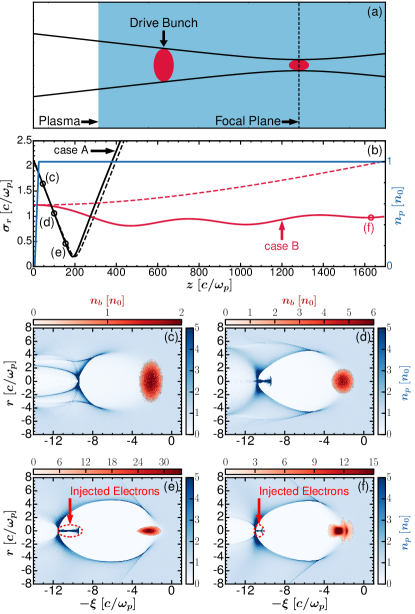
These two regimes are illustrated in Fig. 1 where results from OSIRIS simulations are shown. Simulations results presented in this Letter use the quasi-3D algorithm implemented in OSIRIS which expands the fields and currents into an arbitrary number of azimuthal modes m on an r-z grid Lifschitz et al. (2009); Davidson et al. (2015). For the results presented here, m=0 and m=4 were used for symmetric and asymmetric drivers, respectively. We also use a new customized finite-difference solver to reduce numerical effects induced by the rapid rise in current during injection Li et al. (2017); Xu et al. . The simulations used , with 4 to 128 macro-particles per cell depending on the species and the number of azimuthal modes used.
In case A, a 10 GeV () driver with is initialized with a centroid at , , a normalized emittance , and CS parameters at the plasma entrance of and . For these parameters and the evolution of the spot size is dominated by vacuum diffraction as seen by the agreement with spot size from the simulation with the vacuum evolution(dashed black) in Fig. 1(b). As shown in Fig. 1(c), the wake is being excited in the nonlinear blowout regime when the beam enters the plasma. As the driver spot size decreases, in Fig. 1(c)-(e) the bubble length also increases, thereby reducing the wake velocity allowing the highest energy sheath electrons with to be trapped at the rear of the wake. At spot sizes much less than the maximum blowout radius Lu et al. (2006), the wake wavelength and blowout radius approach their maximum values in Figs. 1(e) and further focusing does not produce any injection.
In case B, an electron drive bunch with the same length, centroid, and energy is focused to the entrance of the plasma with , and CS parameters and . For these parameters and as seen in Fig 1(b) the spot size evolution (solid red) is now dominated by the focusing force of the plasma ion column. It therefore deviates significantly from the vacuum curve (dashed red). In this case the wake elongates as the beam focuses from the ion channel forces leading the self-injection as seen in Fig. 1(f). This regime is more complicated because the ion channel is not fully formed along the entire driver and therefore only the rear of the beam is fully focused. Each slice of the front of the beam oscillates at different betatron frequencies leading to the scalloping Blumenfeld et al. (2007) seen in Fig. 1(f). Each scallop corresponds to a full betatron oscillation within the ion channel.
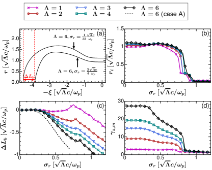
In order to understand and quantify how the wake expansion depends on the evolution of the spot size, we performed numerous simulations using non-evolving drivers with varying and . We tracked the trajectories of the sheath electrons to determine the blowout radius , the ion column length , and the highest forward velocity of sheath electrons at the rear of the wake. In Fig. 2(a), we plot the trajectories of for highest energy sheath electron for and two different driver spot sizes = and respectively. These tracks clearly show that the ion channel size varies for these two spot sizes. In Figs. 2(b)-(d), for each simulation we also plot the initial radius , deviation from the maximum bubble length , and maximum sheath electron forward velocity for the most energetic electron for a variety of spot sizes and . The calculated from case A (dashed black) is also plotted in Fig. 2(b) which is in reasonable agreement with the non-evolving results. The deviation can be explained from beam loading effects from injected electrons.
When , the driver produces a linear wake where the plasma electron perturbation is small, , and the most energetic electrons originate near the axis . The transverse force for a bi-Gaussian beam with a density profile is where . In the large spot size limit, the transverse force of the driver on the sheath electrons is small since most of the driver charge resides outside the initial sheath position and the driver density remains below the particle crossing threshold as Lu et al. (2006).
As the spot size approaches the particle crossing condition, typically around depending on , the wake response transitions from the linear regime to the blowout regime. This transition is signaled by a local maximum in and a rapid rise in and due to formation of a thin plasma sheath. The most energetic sheath electrons now reside at initial positions [Fig. 2(b)] which are insensitive to . As in the linear regime, the transverse force exerted on these electrons increases with the effective charge per unit length as decreases, creating larger blowout radii and bubble lengths as shown in Figs. 2(a) and 2(c). The sheath electrons also exhibit higher [Fig. 2(d)] as more background electrons are blown out by the driver, increasing the density spike and magnitude of at the rear of the wake. Although increases significantly it is still orders of magnitude below so trapping cannot occur. We also note that both and increase with as seen in Fig. 2(c)-(d). When , the transverse driver force on the sheath electrons at peaks as , producing complete electron cavitation within the wake. In this limit, the bubble length , blowout radius , and saturate at their maximum values and are insensitive to .
For an evolving relativistic drive bunch , the wake phase velocity is defined by
| (2) |
To calculate , we need to determine and . We assume that depends only on the instantaneous spot size and, therefore, can be calculated directly from Fig. 2(c). The second term is straightforward to obtain for case A. However, for case B is more complicated to determine because the spot size evolution varies along . The rear evolves as in a fully formed wake while the slices in the front have betatron frequencies that depend on the amount of blowout which leads to a scalloping behavior described above.
For simplicity, we analyze case A in which evolves only as a function z and is well approximated by the vacuum CS parameters, . Using the beta function and the CS relation , we obtain an expression for the spot size evolution , since is constant in vacuum and during most of the injection.
We next approximate and use Eq. (2) to obtain,
| (3) |
From Fig. 2(c) we can see that for and ; therefore, () can be significantly reduced from making injection possible. In Fig. 3(a), we plot (dashed red) calculated from Eq. (3) for case A against (solid black) when from Fig 2(d). The vertical blue dashed lines enclose the region where the injection condition is satisfied . As the driver focuses, self-injection begins near as rapidly increases and crosses . When , the bubble length saturates and injection terminates as increases above .
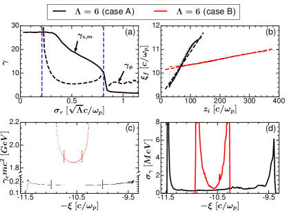
Since is a monotonically decreasing function of in the blowout regime, there is a one-to-one mapping between the initial position and final position of injected electrons as seen in Fig. 3(b). This feature can lead to low absolute slice energy spreads as pointed out in Xu et al. (2017). The dependance of on is given by
| (4) |
where is the average of over the range when in Fig. 2(c). Whereas is determined from the vacuum beta function in case A, an upper bound for in case B can be estimated by integrating and evaluating it at the matched condition . To account for axial variations in the betatron frequency in case B, we also assume a simple model in which half of the drive bunch undergoes betatron oscillations while the remaining half is approximately non-evolving during injection. In Fig. 3(b), excellent agreement is observed between the injected electron phase space and Eq. (4) in both cases. After some optimal acceleration distances, flat phase space distributions in are achieved over some regions of the injected beams as shown in Fig. 3(c). Within the regions enclosed by dashed lines in Fig. 3(c), average energies of 169.7 MeV and 1.86 GeV and projected energy spreads of 1.1% and 0.7% for cases A and B, respectively. In both cases, slice energy spreads as low as 0.5 MeV are also observed along significant regions of the injected electron beams in Fig. 3(d).
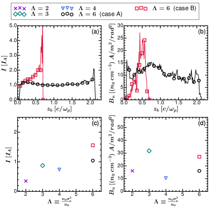
The slice currents and normalized brightnesses of the final injected beams are calculated and plotted in Fig. 4(a)-(b). While the injected beam duration in case A is nearly three times that of case B, larger slice currents of are observed across most of the injected beam in case B. The large variations in the current profile at the front of the injected beam in case B can be attributed to a more slowly evolving wake and beam loading effects from the initial electron injection as noted in Xu et al. (2017). In Fig. 4(b), peak normalized brightnesses of are found for cases A and B, respectively. In Figs. 4(c)-(d), peak slice brightnesses and corresponding slice currents are plotted for various simulations ranging from of 2 to 6. In the results shown, peak brightnesses of at least are achieved across all values of for plasma densities of with slice currents ranging from .
At FACET II, it is anticipated that drive beams with currents in the range of 50-150 kA and durations of 3 fs (1) will be available fac (2016). These parameters match the simulations presented here for , indicating that peak brightnesses as high as and normalized emittances as low as could be produced. We have also carried out simulations with spot size asymmetries () of as high as 15 and the results indicate self-injection still occurs but with a reduction in brightness of less than an order of magnitude up to the maximum asymmetry.
This work was supported by US NSF grant Nos. 1500630 and 1806046, US DOE grant No. DE-SC0010064, and FNAL sub award 544405, and by DE NSFC Grants No. 11425521, No. 11535006, No. 11375006, and No. 11475101, and Thousand Young Talents Program. The simulations were performed on Blue Waters, the National Energy Research Scientific Computing Center (NERSC), and Hoffman2 at UCLA. The corresponding authors are X. L. Xu (xuxinlu04@gmail.com) and T. N. Dalichaouch (tdalichaouch@gmail.com).
References
- Tajima and Dawson (1979) T. Tajima and J. M. Dawson, Phys. Rev. Lett. 43, 267 (1979).
- Chen et al. (1985) P. Chen, J. M. Dawson, R. W. Huff, and T. Katsouleas, Phys. Rev. Lett. 54, 693 (1985).
- Hogan et al. (2005) M. J. Hogan et al., Phys. Rev. Lett. 95, 054802 (2005).
- Blumenfeld et al. (2007) I. Blumenfeld, C. E. Clayton, F.-J. Decker, M. J. Hogan, C. Huang, R. Ischebeck, R. Iverson, C. Joshi, T. Katsouleas, N. Kirby, W. Lu, K. A. Marsh, W. B. Mori, P. Muggli, E. Oz, R. H. Siemann, D. Walz, and M. Zhou, Nature 445, 741 EP (2007).
- Leemans et al. (2014) W. P. Leemans et al., Phys. Rev. Lett. 113, 245002 (2014).
- Leemans et al. (2006) W. P. Leemans, B. Nagler, A. J. Gonsalves, C. Tóth, K. Nakamura, C. G. R. Geddes, E. Esarey, C. B. Schroeder, and S. M. Hooker, Nature Physics 2, 696 EP (2006).
- Wang et al. (2013) X. Wang et al., Nature Communications 4, 1988 EP (2013).
- Hafz et al. (2008) N. A. M. Hafz et al., Nature Photonics 2, 571 EP (2008).
- Litos et al. (2014) M. Litos, E. Adli, W. An, C. Clarke, C. Clayton, S. Corde, J. Delahaye, R. England, A. Fisher, J. Frederico, et al., Nature 515, 92 (2014).
- Adli et al. (2018) E. Adli, A. Ahuja, O. Apsimon, R. Apsimon, A.-M. Bachmann, D. Barrientos, F. Batsch, J. Bauche, V. B. Olsen, M. Bernardini, et al., Nature 561, 363 (2018).
- Steinke et al. (2016) S. Steinke, J. Van Tilborg, C. Benedetti, C. Geddes, C. Schroeder, J. Daniels, K. Swanson, A. Gonsalves, K. Nakamura, N. Matlis, et al., Nature 530, 190 (2016).
- Gonsalves et al. (2019) A. J. Gonsalves, K. Nakamura, J. Daniels, C. Benedetti, C. Pieronek, T. C. H. de Raadt, S. Steinke, J. H. Bin, S. S. Bulanov, J. van Tilborg, C. G. R. Geddes, C. B. Schroeder, C. Tóth, E. Esarey, K. Swanson, L. Fan-Chiang, G. Bagdasarov, N. Bobrova, V. Gasilov, G. Korn, P. Sasorov, and W. P. Leemans, Phys. Rev. Lett. 122, 084801 (2019).
- Kalmykov et al. (2011) S. Y. Kalmykov, A. Beck, S. A. Yi, V. N. Khudik, M. C. Downer, E. Lefebvre, B. A. Shadwick, and D. P. Umstadter, Physics of Plasmas 18, 056704 (2011).
- Xu et al. (2005) H. Xu, W. Yu, P. Lu, V. K. Senecha, F. He, B. Shen, L. Qian, R. Li, and Z. Xu, Physics of Plasmas 12, 013105 (2005).
- Tsung et al. (2004) F. S. Tsung, R. Narang, W. B. Mori, C. Joshi, R. A. Fonseca, and L. O. Silva, Phys. Rev. Lett. 93, 185002 (2004).
- Lu et al. (2007) W. Lu, M. Tzoufras, C. Joshi, F. S. Tsung, W. B. Mori, J. Vieira, R. A. Fonseca, and L. O. Silva, Phys. Rev. ST Accel. Beams 10, 061301 (2007).
- Barletta et al. (2010) W. Barletta et al., Nuclear Instruments and Methods in Physics Research Section A: Accelerators, Spectrometers, Detectors and Associated Equipment 618, 69 (2010).
- Oz et al. (2007) E. Oz et al., Phys. Rev. Lett. 98, 084801 (2007).
- Pak et al. (2010) A. Pak, K. A. Marsh, S. F. Martins, W. Lu, W. B. Mori, and C. Joshi, Phys. Rev. Lett. 104, 025003 (2010).
- Xu et al. (2014) X. L. Xu et al., Phys. Rev. Lett. 112, 035003 (2014).
- Li et al. (2013) F. Li et al., Phys. Rev. Lett. 111, 015003 (2013).
- Yu et al. (2014) L.-L. Yu, E. Esarey, C. B. Schroeder, J.-L. Vay, C. Benedetti, C. G. R. Geddes, M. Chen, and W. P. Leemans, Phys. Rev. Lett. 112, 125001 (2014).
- Hidding et al. (2012) B. Hidding, G. Pretzler, J. B. Rosenzweig, T. Königstein, D. Schiller, and D. L. Bruhwiler, Phys. Rev. Lett. 108, 035001 (2012).
- Katsouleas (1986) T. Katsouleas, Phys. Rev. A 33, 2056 (1986).
- Bulanov et al. (1998) S. Bulanov, N. Naumova, F. Pegoraro, and J. Sakai, Phys. Rev. E 58, R5257 (1998).
- Suk et al. (2001) H. Suk, N. Barov, J. B. Rosenzweig, and E. Esarey, Phys. Rev. Lett. 86, 1011 (2001).
- Xu et al. (2017) X. L. Xu, F. Li, W. An, T. N. Dalichaouch, P. Yu, W. Lu, C. Joshi, and W. B. Mori, Phys. Rev. Accel. Beams 20, 111303 (2017).
- Martinez de la Ossa et al. (2017) A. Martinez de la Ossa, Z. Hu, M. J. V. Streeter, T. J. Mehrling, O. Kononenko, B. Sheeran, and J. Osterhoff, Phys. Rev. Accel. Beams 20, 091301 (2017).
- Lee (1999) S. Y. Lee, Accelerator Physics (WORLD SCIENTIFIC, 1999) https://www.worldscientific.com/doi/pdf/10.1142/3977 .
- Lifschitz et al. (2009) A. Lifschitz, X. Davoine, E. Lefebvre, J. Faure, C. Rechatin, and V. Malka, Journal of Computational Physics 228, 1803 (2009).
- Davidson et al. (2015) A. Davidson, A. Tableman, W. An, F. Tsung, W. Lu, J. Vieira, R. Fonseca, L. Silva, and W. Mori, Journal of Computational Physics 281, 1063 (2015).
- Li et al. (2017) F. Li, P. Yu, X. Xu, F. Fiuza, V. K. Decyk, T. Dalichaouch, A. Davidson, A. Tableman, W. An, F. S. Tsung, R. A. Fonseca, W. Lu, and W. B. Mori, Computer Physics Communications 214, 6 (2017).
- (33) X. Xu, F. Li, F. S. Tsung, T. N. Dalichaouch, W. An, H. Wen, V. K. Decyk, R. A. Fonseca, M. J. Hogan, and W. B. Mori, In preparation.
- Lu et al. (2006) W. Lu, C. Huang, M. Zhou, M. Tzoufras, F. S. Tsung, W. B. Mori, and T. Katsouleas, Physics of Plasmas 13, 056709 (2006).
- fac (2016) FACET-II Technical Design Report No. SLAC-R-1072 (2016).