Observation of multiramp fractional vortex beams and their properties in free space
Abstract
We have experimentally investigated the evolution properties of multiramp fractional vortex beams (MFVBs) in free space, by using a fundamental Gaussian beam reflecting from a phase-modulated spatial light modulator. The issue about the total vortex strength of such MFVBs is systematically addressed, and our result reveals the dependence of the total vortex strength depends on both the non-integer topological charge and the multiramp number contained in initial multiramp phase structures. In the near-field region, vortices contained in MFVBs are unstable and it is hard to effectively confirm the vortex strength for such fields. However, in the far-field region, the evolution of vortices in fields becomes stable and the behavior of vortex strength is confirmed experimentally via measuring vortex structures by interference method. These findings give us an understanding of such complex MFVBs and may lead to potential applications in light signal process and propagation.
pacs:
42.25.-p, 42.25.Bs, 42.25.HzI Introduction
Vortex beams with phase singularities have attracted much attention due to their potential applications, including optical tweezers, optical communication, and quantum information. These vortex beams have the phase structure with the form of , where is the azimuthal angle and is a number known as topological charge. Vortex beams usually have well-defined orbital angular momentum (OAM) when is an integer, and they are also called as integer vortex beams Allen1992 . However, when is a non-integer, then such light fields are known as fractional vortex beams (FVBs). For an FVB, its initial phase structure contains only a single mixed screw-edge dislocation Basistiy1995 . Some unique properties and applications of such FVBs have been proposed, for instance, topologically structured darkness Alperin2007 , fractional OAM momentum entanglement of two photons Oemrawsingh2004 ; Oemrawsingh2005 , quantum entanglement between fractional and integer OAM by single metadevice Kun2018 , and quantum digital spiral imaging Chen2014 . Due to the fractional OAM carried by FVBs, the methods of detecting their OAM have also been studied extensively by using a cylindrical lens Alperin2016 , dynamic angular double slits Zhu2016 , and two-dimensional multifocal array Deng2019 . Furthermore, Tkachenko et. al. have tried to generate a “perfect” FVBs Tkachenko2017 , and the concept of such FVBs is also generalized into the cases of electron beams Bandyopadhyay2017 and acoustic waves Jia2018 ; Hong2015 .
More fundamentally, much attention has been paid to vortex structures of FVBs, since the distribution of vortices can describe their features. The unstable evolution of phase structure for FVBs is revealed during their propagations Basistiy2004 , thus the total vortex strength is often adopted to describe their main characteristics Berry2004 ; Jesus2012 . Total vortex strength for FVBs is first presented by Berry Berry2004 , by assuming an ideal plane wave incident on a non-integer vortex phase plate. Under this condition, total vortex strength increases by unit only when topological charge is slightly lager than any half integer Berry2004 . This result is confirmed in some experiments Leach2004 ; Lee2004 ; Fang2017 . However, in all practical experiments, light sources are finite beams not plane-wave fields. There is a different mechanism on the birth of vortices for FVBs at Fraunhofer zone, which shows experimentally that total vortex strength for FVBs increases by unit only at a number slightly larger than an integer Jesus2012 . Most recently, we reconsidered this issue on the change of total vortex strength for FVBs at Fraunhofer zone, and found both theoretically and experimentally that total vortex strength for FVBs occurs two jumps only when non-integer topological charge is before and after (but very close to) any even integer number WJS2019 . The incident light sources used in Refs. Jesus2012 ; WJS2019 are finite-width Gaussian beams, which are actually similar to the cases in other works Basistiy2004 ; Leach2004 ; Lee2004 ; Fang2017 . In fact, it is a practical way to utilize a Gaussian beam instead of an ideal plane wave to be incident on the designed phase plate with screw-edge dislocation or hologram gratings to generate FVBs. Therefore there are some interesting questions, how the total vortex strength of a practical FVB changes in free space and how it changes as varies. The answer of these questions are important to the potential application of practical FVBs.
On the other hand, FVBs has only a single mixed screw-edge dislocation, and they are generalized into a kind of beams with multiple screw-edge dislocations. For such light fields, one uses to denote non-integer topological charge and to denote a multiramp number contained in initial multiramp phase structures, thus they are so-called multiramp fractional vortex beams (MFVBs). Such MFVBs are used for demonstrating the Hilbert’s hotel paradox Gbur2016 . As stated before, for a practical MFVB when a finite beam is used as an incident field, its total vortex strength remains unsolved. An unified explanation is needed for the vortex strength for both practical FVBs and MFVBs in free space. In order to answer the above problems, we have both theoretically and experimentally investigated the propagation properties of MFVBs (including FVBs) in free space, from their total vortex strength and vortex phase structures.
II Theory
We start from the propagation properties of MFVBs in free space. In practical cases, light sources are always finite in transverse dimensions. Here we consider a fundamental Gaussian beam as an incident beam, and let it pass through (or reflect from) a phase-modulated spatial light modulator (SLM). Then the light field at initial plane (i.e., at the plane of SLM) can be simply given as
| (1) |
where is polar radius, is azimuthal angle, is beam half-width, and is transmission function of the SLM at . For MFVBs, their initial phase structures with multiramp screw-edge dislocations are assumed to be Gbur2016
| (2) |
where is an integer representing the number of multiramp mixed screw-edge dislocations contained in their phase structures, and with the floor function. This function can be expend into the following Fourier series
| (3) |
with and . Therefore, the output light fields of such MFVBs in paraxial optical systems can be seen as a superposition of a series of integer vortex beams, as follows
| (4) |
where are the coordinates at output plane, and is the output light field for an integer Gaussian vortex beams with charge number . For a general optical systems Collins1970 ; Zhao2000 , can be calculated as in Ref. WJS2019 and be given by
| (5) |
where is the Rayleigh distance of initial beam, is the eikonal along the propagation axis, is the wave number, and , , and are the elements of a ray transfer matrix describing a linear optical system. When , Eq. (4) reduces to the case of FVBs with finite beams discussed in Ref. WJS2019 , while when , multiple screw-edge dislocations leads to complex evolution of such MFVBs. By using Eq. (4), we can analytically obtain their light field evolution.
Furthermore, in order to describe the whole property of such MFVBs, it is very important to know the change of their total vortex strength, which is defined by
| (6) |
In calculation, the value of in the above integral may influence the result so that it should be sufficient large. By calculating Eq. (6), one can obtain the change of the total vortex strength of such MFVBs in free space, for which its transfer matrix is simply given by with being the propagation distance.
III Experimental results and discussions
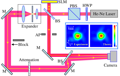
Experimentally, as shown in Fig. 1, MFVBs are generated by a phase-modulation SLM (Holoeye PLUTO-2-VIS-056). The linearly-polarized beam from a He-Ne laser (with nm) first passes through a half-wave plate and a polarized beam splitter, which leads to the intensity of light being well controlled. In our experiment, the measured beam half-width of the initial horizontally-polarized Gaussian beam is mm, which is also used in our theoretical calculation. Through a beam splitter, the incident Gaussian beam splits into two parts. One is reflected into the SLM for generating the designed MFVBs, which is selected from the first order of the modulated beam by using an aperture. The other part is expanded by using two confocal lenses to become a wide-waist Gaussian beam, which is used to interfere with MFVBs, with a crossed angle, for the purpose to verify vortex structures of such MFVBs. When light in the second path is blocked, one can investigate the evolution of such MFVBs at different distance of free space. All intensities are recorded by a CCD camera with high resolution and 14-bit data depth. The inset of Fig. 1 shows both the experimental and theoretical intensity distributions for the MFVB with and at the position of . It is clearly seen that the measured intensity profile is in good agreement with the theoretical result. Thus we only plot the measured intensities below, and the more comparison between the experimental and theoretical distributions can be found in Appendix A (Appendix A, Fig. A1).
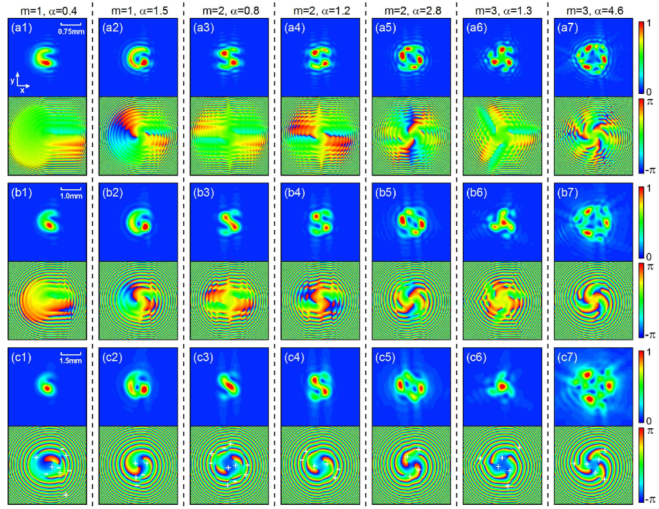
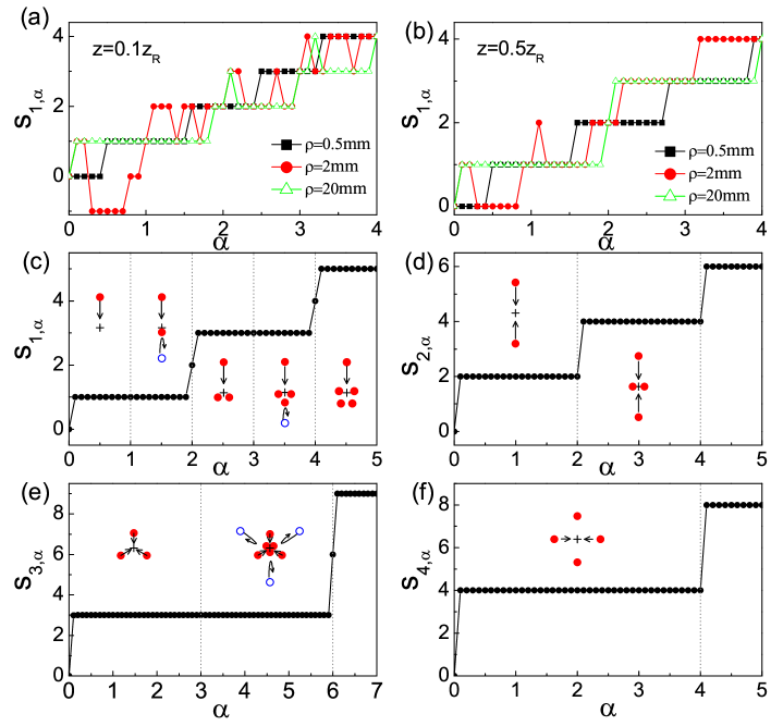
Figure 2 shows the dependence of total vortex strength on the parameter of topological charge of MFVBs in free space. As mentioned above, when , it reduces to the cases of conventional FVBs. In our recent work WJS2019 , we have clearly demonstrated that total vortex strength for an FVB occurs a unit jump only when is before and after (but very close to) any even integer number due to two different mechanisms for generation and movement of vortices in focusing systems, which correspond to the cases of far-field region (i.e., Fraunhofer diffraction region). Here we further show that, for a practical FVB (i.e., the incident light fields with finite beam-width), its is, in principle, a constant during its propagation in free space. However, due to the complex evolution and unstable phase structures in the near-field region Basistiy2004 ; Leach2004 ; Fang2017 (roughly when the propagation distance is smaller than ), the value of for practical FVBs or MFVBs are dependent on the integral loop of Eq. (6) (i.e., the value of ), see Figs. 2(a) and 2(b). From Figs. 2(a) and 2(b), it is clearly seen that are unstable because in the outer regions of the beams there are a series of positive and negative vortices (see Fig. 3), which may be included or not included when the loop is small. When the loop is sufficient large and the propagation distance increase, trends to be stable and finally becomes a constant during propagation, see the cases of mm at in Fig. 2(b).
In Figs. 2(c-f), it shows the steady change of at under the integral with a sufficient large loop of . Clearly, for practical FVBs or MFVBs in free space, when is an even number, the value of jumps with amplitude when is slightly larger than any even integer with also being an integer. When is an odd number, its value of first jumps at the place where is slightly before any , and then exactly equals to at , and there is another kind of jumps happening when is slightly larger than . All jumps have the amplitude .
Meanwhile, we would like to emphasize that Berry’s results for FVBs in Ref. Berry2004 can be recovered under the ideal case that the incident light is an ideal plane wave. Or say, one can approximately mimic Berry’s results when the incident beam has a wide beam-width in the near-field region, with an optimal integral loop. However, in principle, the total vortex strength of any practical FVBs or MFVBs with finite beam-widths always obeys the following relation
The above rule for MFVBs is also different from the result in Ref. Gbur2016 , which are only suitable for the ideal case that the incident light is the plane wave.
In order to understand the above rule of total vortex strength of practical FVBs and MFVBs, it is important to observe the intensity and phase evolution of these beams in both the near-field and far-field regions of free space. In Fig. 3, it shows clearly that there are open dark structures in the near-field regions of FVBs with when approaches to half integer (or when ). These open dark structures are actually corresponding to the vortex-pair generation or pairs of positive and negative vortices Berry2004 ; Leach2004 , see the phase distributions in Figs. 3(a1) and 3(b1). These positive and/or negative vortices have complex evolution in near-field regions. However, as the propagating distance increases, through a careful observation, almost all vortices first generate, then evolute, and finally annihilate with their nearest opposite-sign vortices (see Appendix B, Fig. A2). This property is actually the same as the evolution of those optical vortex knots Dennis2010 . In the far-field region, all remained vortices are stable and may rotate an angle of due to Gouy phase Vasnetsov1998 . Meanwhile, as is close to the far-field region, there exist only a finite number of vortices, from which one can easily determine the value of .
For examples, for MFVBs with and , in Fig. 3, it also shows how the beams evolute from the near-field to far-field regions. There are more complex intensity and phase structures, and pairs of vortices form, evolute, and annihilate in near-field regions. This is the reason that a finite integral loop used in Eq. (6) is hard to find a correct result in near-field regions. However, as the same as the cases of , all remained vortices for MFVBs also become stable as approaches the far-field regions.
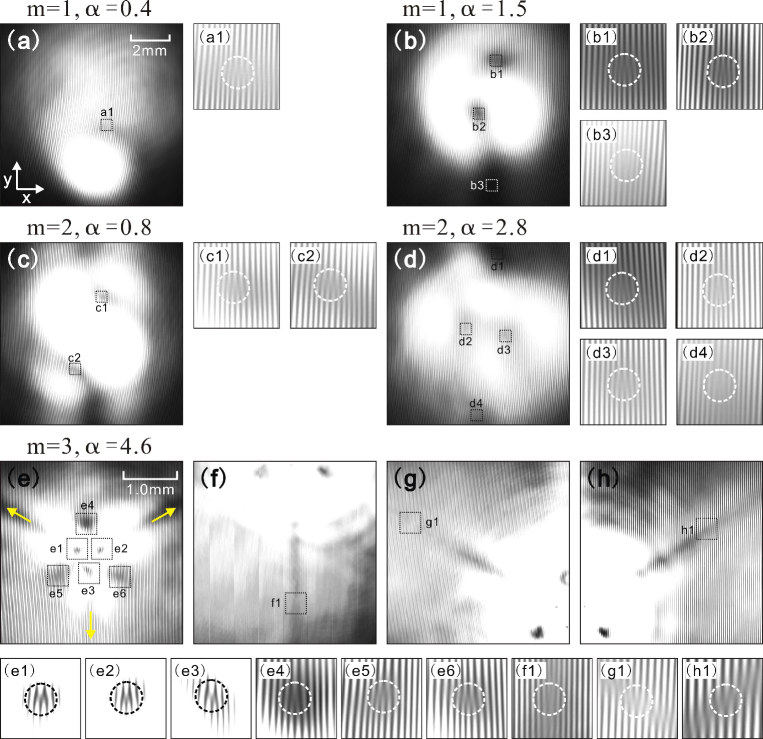
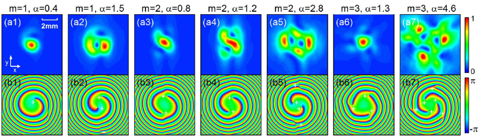
Figure 4 further demonstrates the measured intensity distributions and their corresponding phase structures for FVBs and MFVBs at the far-field region (). By including the vortex sign, the value of total vortex strength is coincidence with the prediction of Figs. 2(c-f), and the distributions of stable vortices for practical MFVBs at the far-field region are also displaced in Fig. 4. For example, when and , it is observed that there already exist two +1 vortices. But when and , there are still two +1 vortices to be observed. This result is different from that in Ref. Gbur2016 , where the value of jumps when . There are similar situations for MFVBs with (also see Appendix C). It should be emphasized that the vortices in outer low-intensity area are not only important to but also to the issues about higher transverse-vector components of beams.
For practical FVBs with , the rule of vortex movement and generation as a function of is schematic in Fig. 2(c). In Figs. 2(d)-2(f), it further shows the layout of vortex movement and generation with the increase of . All these results are summarized from phase distributions around a circle loop with a very large radius at far-field regions (see the Appendix C). These rules are important to understand the evolution of vortices for real MFVBs and FVBs in far-field regions.
In order to obtain direct evidences on total vortex strength and phase structures of MFVBs, we have performed the interference experiments by using these typical MFVBs with a titled wide-width Gaussian beam, shown in Fig. 1, when the optical path after the first beam splitter is not blocked. From the above discussions, we know that the light fields (containing vortices) at far-field zone are stable. Therefore, the interference phenomena are recorded by the CCD camera at those far-field regions. Figure 5 shows some typical interference patterns at the plane of , from which one can identify all vortices indicated by fork-like interference patterns. The opening direction of fork-like pattern determines the sign of vortex. As shown in Fig. 5(a), for an FVB with and , there is only one downward fork-like pattern detected, and its feature shows a vortex with +1 charge existing in the field. When and , one can find three fork-like interference patterns on the image, however two of them are downward and the other is upward. This tells us that there are two vortices with +1 charge and one vortex with -1 charge, thus one still have in this case. For MFVBs with and in Figs. 5(c, d, e), respectively, through a carefully experimental observation (also see Appendix D), we can conclude that both the number and sign of all vortices for MFVBs in far-field regions are verified by using such interference patterns. Here we emphasize that when is an odd number, there are possible opposite-sign vortices existed in the outer extremely-low intensity region at far-field zone, which makes the interference measurement become very difficult, however, by using 2- lens system, it will reduce the difficulty to measure these vortices at focal plane. The measured result of total vortex strength on MFVBs and FVBs is in good agreement with the theoretical prediction of Fig. 2.
IV Summary
In a conclusion, we have studied the total vortex strength and vortex structures of MFVBs in practical situations which are generated by using a finite Gaussian beam not an ideal plane-wave light field. In principle, when MFVBs propagate in free space, their total vortex strength is always conserved. However, due to the unstable properties of intensity and phase structures in near-field region, it is better to determine the value of total vortex strength versus the topological charge for such MFVBs in far-field zone. Our result offers a rule of the total vortex strength as a function of topological charge for such practical MFVBs, which is different from the results of both the ideal plane-wave FVBs Berry2004 and MFVBs Gbur2016 . Although one might mimic the ideal results in near-field zone by using the wide-width light fields, the essential propagating properties of practical MFVBs and FVBs in free space are disclosed to have totally different behaviors, especially in far-field regions, which are never observed before. Our result also suggests that it is more convenient to directly evaluate the total vortex strength at far-field zone, where all vortices are stable and countable. Our result is important for micro-particle trapping and provides an understanding for complex fractional vortex structured light beams in practical optical applications.
Acknowledgements.
This work was supported by the Fundamental Research Funds for the Center Universities (No. 2017FZA3005); National Key Research and Development Program of China (No. 2017YFA0304202); National Natural Science Foundation of China (NSFC) (grants No. 11674284); and the Fundamental Research Funds for the Center Universities (No. 2019FZA3005).Appendix A Comparison of the measured intensity with the theoretical results for MFVBs propagating from near-field to far-field regions
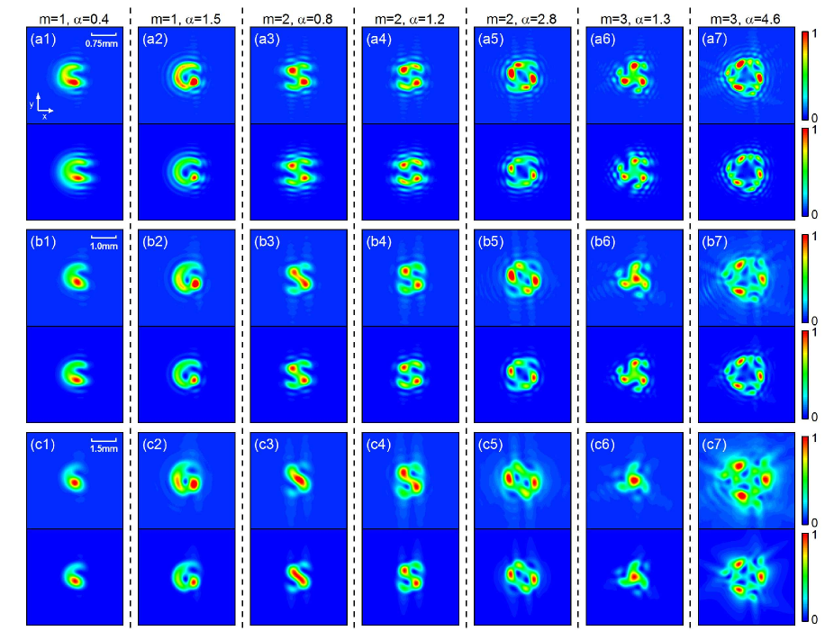
Figure A1 shows the experimental measured intensities and corresponding theoretical intensities of the MFVBs. The measured intensities are in good agreement with theoretical intensities for the MFVBs with different and . Therefore, the theoretical equation of Eq. (4) can describe the field evolution of such MFVBs propagating in free space and the phase vortex structure from Eq. (4) can explain the complex dark-field structures at different propagating distance.
Appendix B The evolution of vortices at near-field region
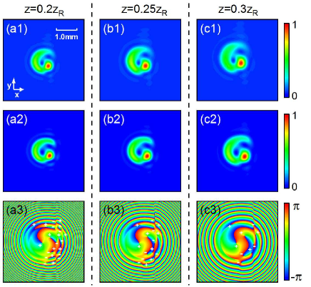
Figure A2 shows the evolution of the vortices for the FVB with at near-field region. It is observed that the measured intensity is in a good agreement with the theoretical result. Furthermore, it is observed in Fig. A2(a3) that there are pairs of vortices with opposite charges at . As the beam propagates from to , see Figs. A2(b3) and (c3), pairs of vortices with opposite charge annihilate each other.
Appendix C The phase of the MFVBs under a large at far-field region
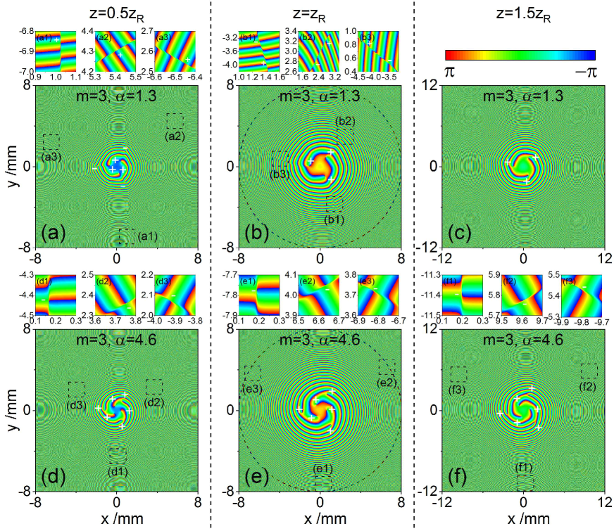
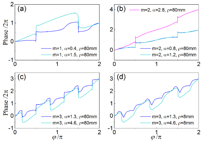
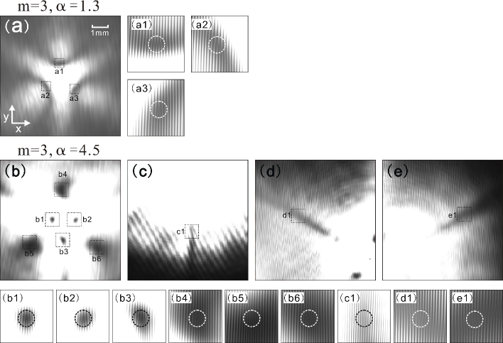
Figure A3 shows the theoretical phase of some typical MFVBs within the region contained all vortices at different propagating positions. It is observed that in Fig. A3(a) that for MFVBs with at there are three charge +1 vortices at central region and three pairs of opposite-sign vortices with charge at outer region. Therefore, the total vortex strength As distance increases to 1.5, see Figs. A3(b) and (c), the outer three pairs of unstable vortices annihilate each other. Finally the phase distribution becomes stable and the three charge +1 vortices remain. However, it is seen in Fig. A3(d) that for MFVBs with at there are nine vortices which is similar to the case of . These nine vortices maintain as the beam propagates to . These two different evolution behaviors of vortices between and due to two different mechanisms which have summarized in the insets of Fig. 2(e). Figs. A4(a, b, c) demonstrate the phase curves as a function of azimuthal angle at a sufficient large loop on phase plane with the radius mm at . These results verify the total vortex strength in Fig. 2. In addition, Fig. A4(d) shows the phase as a function of azimuthal angle under mm at . As compared with the cases of phase at mm, the accumulation of the phase is all equal to 6 on both the loop of mm and mm. It tells us that the phase in Figs. A3(b) and (e) have already contained all the vortices and total vortex strength is equal to 3.
Appendix D The measured interference patterns at far-field region
Figure A5 give more experimental results of the interference patterns of MFVBs with a title wide-width Gaussian beam measured at far-field region. It is seen in Fig. A5(a) that there are three downward fork-like pattern detected, which indicates that there are three +1 vortices for . For , there are total nine fork-like patterns, six of which are downward while the other three are upward. Therefore, the total vortex strength . It confirms again our prediction of total vortex strength in Fig. 2.
References
- (1) L. Allen, M. W. Beijersbergen, R. J. C. Spreeuw, and J. P. Woerdman, Phys. Rev. A 45, 8185-8819 (1992).
- (2) I. V. Basistiy, M. S. Soskin, and M. V. Vasnetsov, Opt. Commun. 119, 604-612 (1995).
- (3) S. N. Alperin, and M. E. Siemens, Phys. Rev. Lett. 119, 203902 (2017).
- (4) S. S. R. Oemrawsingh, A. Aiello, E. R. Eliel, G. Nienhuis, and J. P. Woerdman, Phys. Rev. Lett. 92, 217901 (2004).
- (5) S. S. R. Oemrawsingh, X. Ma, D. Voigt, A. Aiello, E. R. Eliel, G. W. ’t Hooft, and J. P. Woerdman, Phys. Rev. Lett. 95, 240501 (2005).
- (6) K. Huang, H. Liu, S. Restuccia, M. Q. Mehmood, S. T. Mei, D. Giovannini, A. Danner, M. J. Padgett, J. H. Teng, and C. W. Cheng, Light: Sci. Appl. 7, 17156 (2018).
- (7) L. X. Chen, J. J. Lei, and J. Romero, Light: Sci. Appl. 3, e153 (2014).
- (8) S. N. Alperin, R. D. Niederriter, J. T. Gopinath, and M. E. Siemens, Opt. Lett. 41, 5019-5022 (2016).
- (9) J. Zhu, P. Zhang, D. Fu, D. Chen, R. Liu, Y. Zhou, H. Gao, and F. Li, Photon. Res. 4, 187-190 (2016).
- (10) D. Deng, M. C. Lin, Y. Li, and H. Zhao, Phys. Rev. Applied 12, 014048 (2019).
- (11) G. Tkachenko, M. Chen, K. Dholakia, and M. Mazilu, Optica 4, 330-333 (2017)
- (12) P. Bandyopadhyay, B. Basu, and D. Chowdhury, Phys. Rev. A 95, 013821 (2017).
- (13) Y. R. Jia, Q. Wei, D. J. Wu, Z. Xu, and X. J. Liu, Appl. Phys. Lett. 112, 173501 (2018).
- (14) Z. Y. Hong, J. Zhang, and B. W. Drinkwater, EPL 110, 14002 (2015).
- (15) I. V. Basistiy, V. A. Pas’ko, V. V. Slyusar, M. S. Soskin, and M. V. Vasnetsov, J. Opt. 6, S166-S169 (2004).
- (16) M. V. Berry, J. Opt. A: Pure Appl. 6, 259-268 (2004).
- (17) A. J. Jesus-Silva, E. J. S. Fonseca, and J. M. Hickmann, Opt. Lett. 37, 4552-4554 (2012).
- (18) J. Leach, E. Yao, and M. J. Padgett, New J. Phys. 6, 71 (2004).
- (19) W. M. Lee, X. C. Yuan, and K. Dholakia, Opt. Commun. 239, 129-135 (2004).
- (20) Y. Q. Fang, Q. H. Lu, X. L. Wang, W. H. Zhang, and L. X. Chen, Phys. Rev. A 95, 023821 (2017).
- (21) Jisen Wen, Li-Gang Wang, Xihua Yang, Junxiang Zhang, and Shi-Yao Zhu, Opt. Express 27, 893-5904 (2019).
- (22) G. Gbur, Optica 3, 222-225 (2016).
- (23) S. A. Collins, J. Opt. Soc. Am. 60, 1168-1177 (1970).
- (24) S. Wang, and D. Zhao, Matrix Optics, (Springer, 2000).
- (25) M. R. Dennis, R. P. King, B. Jack, K. O’Holleran, and M. J. Padgett, Nat. Phys. 6, 118-121 (2010).
- (26) M. V. Vasnetsov, L. V. Bastisty, and M. Soskin, Proc. SPIE 3487, 29-33 (1998).