Sharif University of Technology] Department of Chemistry, Sharif University of Technology, Tehran, Iran Sharif University of Technology] Department of Chemistry, Sharif University of Technology, Tehran, Iran
Graphenylene–1 Membrane: An Excellent Candidate for Hydrogen Purification and Helium Separation
Abstract
In this study, we use the density functional theory (DFT) calculations and the molecular dynamics (MD) simulations to investigate the performance of graphenylene–1 membrane for hydrogen (\ceH2) purification and helium (\ceHe) separation. The stability of this membrane is confirmed by calculating its cohesive energy. Our results show that a surmountable energy barrier for \ceH2 () and \ceHe () molecules passing through graphenylene–1 membrane. At room temperature, the selectivity of \ceH2/\ceCO2, \ceH2/\ceN2, \ceH2/\ceCO and \ceH2/\ceCH4 are obtained as , , and , respectively. Furthermore, we demonstrate that graphenylene–1 membrane exhibits the permeance of \ceH2 and \ceHe molecules are much higher than the value of them in the current industrial applications specially at temperatures above 300 and 150 , respectively. We further performed MD simulations to confirm the results of DFT calculations. All these results show that graphenylene–1 monolayer membrane is an excellent candidate for \ceH2 purification and \ceHe separation.
keywords:
Graphenylene–1 Membrane, Hydrogen Purification, Helium Separation, DFT Calculations, MD Simulations, Selectivity and Permeance1 Introduction
Nowadays, depletion of the fossil fuel and increased environmental pollution have been a global concern. It seems that it is essential to exploit renewable and clean energy instead of the fossil fuels. Recently, \ceH2 is regarded as one of the most efficient substitutes of the fossil fuels because of its high energy content, clean burning product, natural abundance and renewable nature. Therefore, it will be the most attractive and promising energy source in the future 1, 2, 3, 4, 5, 6.
Currently, steam-methane reforming (\ceCH4 + H2O -¿ CO (CO2) + H2) is the common technology for \ceH2 production in industry, which is an economical process at a large scale 7, 8. So, there are impurities of \ceCO, \ceCH4, \ceCO2 and \ceN2 in this reaction. These impurities can severely cause bad influences on energy content, storage and utilization of \ceH2 9, 10, 11. Consequently, high-quality purification of \ceH2 is very important and finding an effective and low-cost approach for it is very challengable.
Moreover, \ceHe is an irreplaceable natural resource. Although, it is the second most abundant element in the universe, the shortage of it will become increasingly serious 12, 13, 14. Today, demand of \ceHe in various industrial and scientific applications such as cryogenic science and silicon-wafer manufacturing is increasing 15, 16. In addition, the isotope, \ce^3He, is important for fundamental researches in physics 17. It seems that development of low-cost energy strategy for \ceHe separation from natural gases is highly desired.
The common traditional \ceH2 purification technologies are cryogenic distillation and pressure swing adsorption. However, these technologies have disadvantages such as complicated operation and high energy consumption. Recently, membrane separation technology has been widely used because of low energy consumption, low investment cost and facile operation 18, 19, 20, 21, 22. In this regrad, many advanced membrane materials, ranging from tens of nanometres to several micrometres in thickness, have been developed for gas separation, including polymeric membranes 23, metal organic framework 24, dense metal membranes 25, zeolite membranes 26 and etc.
Generally, a suitable \ceH2 purification membrane should have two important characteristics: (1) at least interaction between \ceH2 and membrane; (2) a certain energy barrier to distinguish between \ceH2 and other gases. Therefore, the selectivity and permeance are two important factors to evaluate the performance of \ceH2 purification membrane 27. An ideal two-dimensional (2D) membrane for gas separation would show an appropriate balance between the selectivity and the permeance factors. However, traditional membrane usually encounter the selectivity-permeance trade-off problem 28, 29, 30. The permeance is inversely proportional to the thickness of the membrane. So, one-atom thin membrane can be an ideal candidate for \ceH2 purification 31.
The design and synthesis of suitable 2D membranes for gas separation have attracted wide attention in theoretical and experimental contexts 32, 33, 34. Recently, graphene and carbon allotropes related sp–sp2 hybridization have been proposed as the membranes for gas separation 35, 36. These structures are formed by benzene rings linked with acetylenic linkages, graphyne, or diacetylenic linkages, graphdiyne. In an important study, Liu et al. synthesized graphenylene–1 and graphenylene–2 by replacing ethynylene groups of -graphyne and graphdiyne with -phenylene units, respectively 37. These new structures have purely sp2-hybridized 2D carbon structures with a hexagonal symmetry.
Many chracteristics of these carbon allotropes monolayer membranes such as highly diversified structures, periodically distributed uniform pores and high chemical and mechanical stability make them an appropriate candidate for the gas separation process 18, 38. It is noteworthy that the acetylenic linkages in the structure of graphyne creates periodic pores, which the size of them can be controlled by the length of the linkages 39.
Recently, many studies have been done to investigate the gas separation process through carbon allotropes monolayer membarnes. For example, Cranford et al. performed MD simulations to obtain the temperature and pressure dependence of the gas purification in graphdiyne 40. Zhang et al. showed that graphyne–1 is unsuitable membrane for \ceH2 purification due to small pore size and insuperable diffusion energy barrier. In addition, graphdiyne, with larger pores, demonstrates a high selectivity for \ceH2 over large gas molecules such as \ceCH4, but a relatively low selectivity over small molecules such as \ceCO and \ceN2 41. To conquer this problem, Li et al. demonstrated that Ca-decorated graphyne has good \ceH2 storage capacity 42. Moreover, Sang et al. designed two dumbbell-shaped graphyne membrane and used DFT calculations and MD simulations to invetigate the performance of it. Their calculations showed that the designed membrane is suitable for \ceH2 separation 44.
The question that arises here is that: Can we further enhance the performance of graphyne-based membrane for \ceH2 purification? It seems that the pore size of graphyne is an important factor. So, we can obtain appropriate pore sizes by changing the elementary structure of graphyne to improve the selectivity and the permeance factors for \ceH2 purification process.
In the present study, we use DFT calculations and MD simulations to investigate the performance of graphenylene–1 monolayer membrane which synthesized by Liu et al. 37, for \ceH2 purification and \ceHe separation. First, we examine the stability of this monolayer membrane by calculating its cohesive energy. Then, the energy barriers of the gas molecules passing through graphenylene–1 membrane were calculated using DFT calculations to obtain the selectivity and the permeance of the membrane. Moreover, the results of DFT calculations were confirmed by MD simulations. Our results show that high selectivity and excellent permeance for \ceH2/gas (\ceCO, \ceCH4, \ceCO2, \ceN2) and \ceHe/gas (\ceH2, \ceCO, \ceCH4, \ceCO2, \ceN2, \ceNe, \ceAr) at differrent temperatures.
2 Computational Methods
DFT calculations were carried out to optimize the structure of graphenylene–1 monolayer, compute its stability, calculate the energy barrier of the gas molecules passing through it and describe the electron density iso-surfaces for the gases interacting with porous graphenylene–1 monolayer. The Perdew-Burke-Ernzerhof (PBE) function under the generalized gradient approximation (GGA) is employed by the spin-unrestricted all-electron DFT calculations which interprets the nonhomogeneity of the true electron density using the gradient of charge density for exchange-correlation function. We adopt a dispersion correction for DFT calculations with Grimme’s method by adding a semi-empirical dispersion potential. The double numerical plus polarization (DNP) basis set is used to expand electronic wave function. The self-consistent field (SCF) calculations are performed with a convergence criterion of a.u. on the total energy to ensure the high-quality results. In addition, a real-space global orbital cutoff radius of and a smearing point of 0.002 Ha are chosen in all calculations. The Brillouin zone is expressed using a Monkhorst-Pack meshes. A vacuum thickness is used to prevent the interaction between two sheets. A large 2D sheet in xy plane including 244 atoms of C and H is constructed to represent the 2D graphenylene–1 atomic layer. Iso–electron density surfaces were obtained by the Gaussian 09 program 45 at the B3LYP/6-31G(d) level with the D3 correction 46 were plotted at isovalues to determine the pore size of the membrane. On the basis of this method, we find the potential energy curves of a single \ceH2, \ceHe, \ceNe, \ceCO2, \ceCO, \ceN2, \ceAr and \ceCH4 molecule passing through the pore center of the membrane.
Moreover, MD simulations were performed to analyze \ceH2 purification and \ceHe separation using Forcite code in Material Studio software under a canonical (NVT) ensemble conditions and the temperature (in the range of 200-600 ) was controlled by the Anderson thermostat. Periodic boundary conditions were applied in all three dimensions. The interatomic interactions were explained by a condensed-phase optimized molecular potential for atomistic simulation studies (COMPASS) force field 47, which has been widely used to compute the interactions between the gases and the carbon-based membranes 48, 49, 50. The cutoff distance of the Van der Waals interactions was set as and the particle-particle particle-mesh (PPPM) technique used to calculate the electrostatic interactions. The cubic boxes with the dimensions of for simulations were trisected along the z-direction with two pieces of graphenylene–1 membrane, forming one gas reservoir in the middle and two vacuum regions on both sides. During MD simulations, the carbon atoms on the edge of membrane were always fixed, while all the other atoms in the system were fully relaxed. The gas mixtures involved 120 \ceH2 molecules, 40 \ceH2O molecules, 40 \ceCO2 molecules, 40 \ceN2 molecules, 40 \ceCO molecules and 40 \ceCH4 molecules. The total simulation time was , and Newton’s equations were integrated using timesteps.
3 Results and Discussion
| \ceHe | \ceNe | \ceH2 | \ceCO2 | \ceAr | \ceN2 | \ceCO | \ceCH4 | |
|---|---|---|---|---|---|---|---|---|
| ()43 | 2.60 | 2.75 | 2.89 | 3.30 | 3.40 | 3.64 | 3.76 | 3.80 |
| () | 3.175 | 3.275 | 3.300 | 4.550 | 3.725 | 3.850 | 3.875 | 4.550 |
| () | -0.027 | -0.074 | -0.077 | -0.114 | -0.118 | -0.113 | -0.119 | -0.114 |
| () | 0.178 | 0.296 | 0.384 | 2.017 | 2.271 | 1.472 | 1.407 | 3.167 |
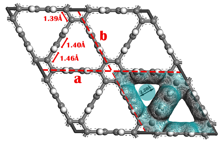
The optimized structure of a 2D graphenylene–1 monolayer membrane is shown in FIG. 1. The optimized crystal lattices are = = and actually, graphenylene–1 monolayer membrane can be seen as benzene rings linked together, resulting in a 2D network with periodically distributed pores. In graphenylene–1 monolayer, the length of C–C bonds involved in vertical benzene rings is while the length of C–C bonds presented in in-plane benzene rings is . All linked C–C bonds have a uniform length of which are in good agreement with the previous theoretical predictions52, 54, 53. Moreover, we also show the electron density iso–surfaces of pores in graphenylene–1 monolayer membrane. As shown in FIG. 1, the pore of this monolayer membrane have a trigonal shape with the size of .
The stability of the designed membranes is a crusial factor for their experimental applications. So, we calculate the cohesive energy of graphenylene–1 monolayer membrane to investigate the stability of it.
The cohesive energy representing the energy required to decompose the membrane into isolated atoms, is defined as 55
| (1) |
where is the number of atom in the membrane, and denote the isolated atom and the total energies of the membrane, respectively. Our DFT calculations show that the cohesive energy of graphenylene–1 membrane is /atom which is a little smaller than that of graphene (/atom), but is much higher than that of silicene (/atom) 56. The value of cohesive energy indicates that graphenylene–1 monolayer is a strongly bonded network and are thus rather stable.
The interaction energy between the gas molecules and membrane can be obtained as
| (2) |
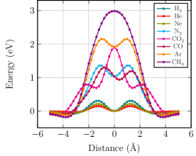
where , and are the total energy of the gas molecule adsorbed on graphenylene–1 monolayer, the energy of isolated gas molecule and the energy of graphenylene–1 mononolayer, respectively. In FIG. 2, the minimum energy pathways for the gas molecules (including \ceH2, \ceHe, \ceCO, \ceCH4, \ceCO2, \ceN2, \ceNe and \ceAr) passing through the membrane are plotted in the distance from the center of the pore.
| membrane | \ceHe/\ceNe | \ceHe/\ceH2 | \ceHe/\ceCO2 | \ceHe/\ceAr | \ceHe/\ceN2 | \ceHe/\ceCO | \ceHe/\ceCH4 |
|---|---|---|---|---|---|---|---|
| graphenylene–1 (This work) | |||||||
| CTF-0 57 | |||||||
| Silicene 58 | — | — | — | — | — | ||
| Polyphenylene 59 | — | ||||||
| Graphdiyne 38 | — | — | — | — | — | ||
| g-C3N4 12 | — | ||||||
| C2N7 8 | — | — |
Furthermore, in order to investigate the process which the gases passing through the membrane, we define the diffusion energy barrier for the gas molecules as
| (3) |
where , and denote the diffusion energy barrier, the total energy of the gas molecules and the pore center of graphenylene–1 membrane at the transition state and the steady state, respectively. The kinetic diameters () of the studied gases, the adsorption height () of the steady state of the gas molecules and the pore center of graphenylene–1 monolayer with corresponding adsorption energy () and the energy barriers of the gases passing through graphenylene–1 membrane are given in Table 1.
As is clear in Table 1, the diffusion energy barrier enhances with increasing the kinetic diameter of the most studied gases. Moreover, there are a surmountable value of diffusion energy barrier for \ceHe () and \ceH2 () molecules passing through the membrane. The calculated adsorption energies of the gases are in the range of to and the corresponding adsorption heights are in the range of to , which demonstrate the physical adsorption nature of the studied gases on the pore center of graphenylene–1 membrane. The adsorption heights of impurity gases are higher than that of \ceHe and \ceH2 molecules. It show that \ceHe and \ceH2 molecules are closer to the pore center of the membrane than other gases. The adsorption energy of \ceHe and \ceH2 molecules are and , respectively which are smaller than of other gas molecules except \ceNe molecule. So, \ceHe and \ceH2 molecules are easier to desorb from the membrane and pass through it.
| membrane | \ceH2/\ceCO2 | \ceH2/\ceN2 | \ceH2/\ceCO | \ceH2/\ceCH4 |
|---|---|---|---|---|
| graphenylene–1 (This work) | ||||
| -GYH 44 | ||||
| Graphenylene 60 | ||||
| -GYN 44 | ||||
| Porous graphene 61 | — | — | — | |
| g-C2O 62 | ||||
| Graphdiyne 41 | — |
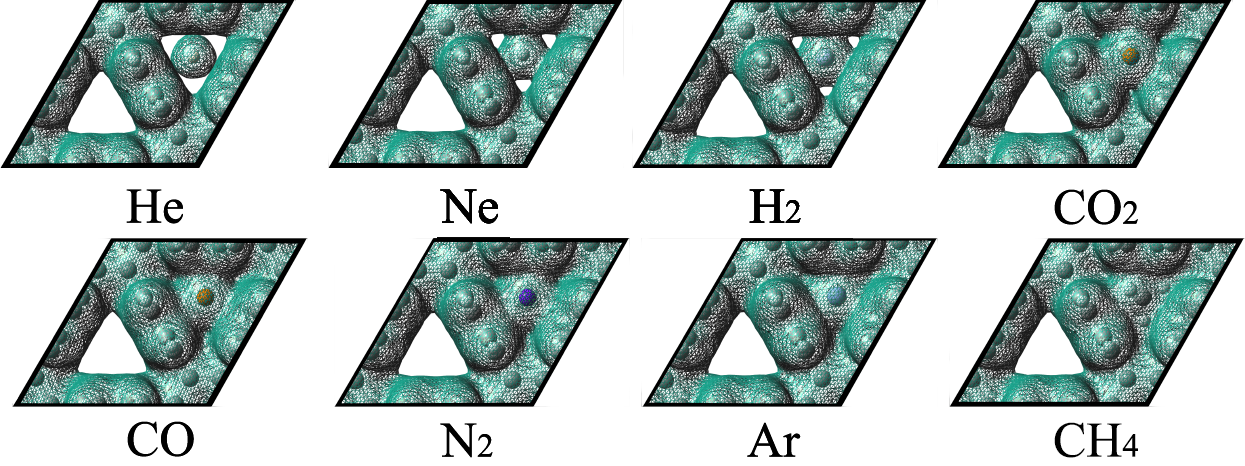
Moreover, we plotted iso–electron density surfaces in FIG. 3 to study the electron overlaps between the gas molecules and graphenylene–1 monolayer membrane. At least electron overlap between \ceHe molecule and the membrane causes the energy barrier for \ceHe among other gas molecules to be the lowest. In addition, more electron overlap between \ceCH4 molecule and graphenylene–1 membrane makes the highest energy barrier for \ceCH4 molecule.
As is well known, the performance of a membrane for the gas separation process is evaluated by the selectivity and the permeance factors. So, we study these factors for the gas molecules passing through graphenylene–1 monolayer sheet.
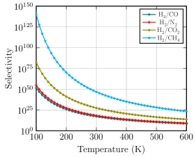
Regarding the calculated diffusion energy barriers, we can use Arrhenius equation to obtain the selectivity for =He and \ceH2 over other gas molecules as
| (4) |
where is the diffusion rate, is the diffusion prefactor which is assumed to be identical for all gases (=) 44, is the diffusion energy barrier, is the molar gas constant and is the temperature.
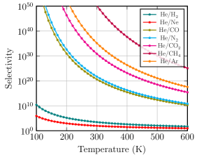
We plotted the calculated selectivities for \ceHe and \ceH2 molecules over other gases at different temperatures in FIG. 4. As is clear, the selectivity for \ceHe and \ceH2 gases decreases with increasing temperature. Moreover, the calculated selectivities for \ceHe and \ceH2 molecules over impurity gases for graphenylene–1 membrane and other proposed porous membranes at room temperature () are compared in Table 2 and Table 3, respectively. It can be concluded from Table 2, graphenylene–1 membrane shows high selectivity for \ceHe molecule among other proposed membranes especially towrad \ceH2, \ceCO2 and \ceCH4 gases. Also, the selectivity of \ceH2/\ceCO2, \ceH2/\ceN2, \ceH2/\ceCO and \ceH2/\ceCH4 are , , and , respectively in Table 3. The results represent that graphenylene–1 membrane shows high selectivity for \ceHe and \ceH2 molecules in comparision with other proposed membranes.
Besides the selectivity, the permeance factor which determines the separation efficiency, is another important factor to characterize the performance of a membrane.
Considering the calculated energy barriers, we further used the kinetic theory of the gases and the Maxwell-Boltzmann velocity distribution function to investigate the permeances of the gas molecules passing through graphenylene–1 membrane. The number of gas particles colliding with graphenylene–1 monolayer can be obtained as
| (5) |
where is the gas pressure, here it is taken as Pa, is the molar mass, is the molar gas constant and is the gas temperature. The probability of a particle diffusing through the pore of the membrane can be expressed as
| (6) |
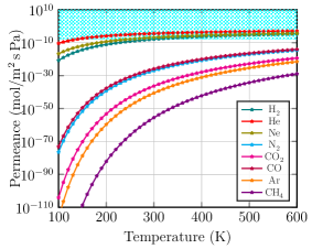
where denotes the velocity corresponding to the energy barrier and is the Maxwell velocity distribution function. So, the flux of the particles can be written as 27. We assume that pressure drop equals . Then, we can obtain the permeance factor of the gas molecules passing through the membrane by .
In FIG. 5, we plotted the permeances of the studied gases passing through graphenylene–1 membrane as a function of temperature. The cyan dotted area indicates the industrially acceptable standard for gas separation. As is clear in FIG. 5, with the increase of temperature, the permeance of each gas increases largely, while the divergence of permeances between different gases decreases. Also, we conclude that graphenylene–1 membrane exhibits the permeance of \ceH2 and \ceHe gas molecules are much higher than the value of them in the current industrial applications at temperatures above and respectively, while the permeances of \ceCO2, \ceN2, \ceCO, and \ceCH4 are still much lower than the industrial limit even at .
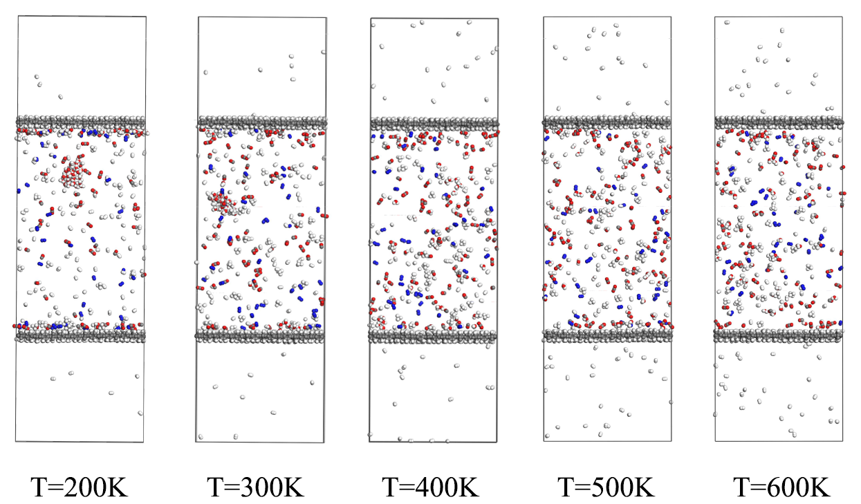
To confirm the results of DFT calculations, MD simulations were performed to investigate the process of \ceH2 molecule passing through graphenylene–1 membrane and estimate \ceH2 permeance in the temperature range of 200–600 . The final MD simulated configurations of the gas molecules passing through the porous graphenylene–1 membrane at different temperatures are shown in FIG. 6. The gases adsorbed on the surface of the membrane by the Van der Waals interaction. Then, they linger on the surface for a few picoseconds before passing through the monolayer membrane, since the gas concentration is different between the gas reservoir (containing \ceH2O, \ceCO2, \ceN2, \ceCO and \ceCH4) and the vacuum space. After simulation, we can see that there are 8, 15, 34, 42 and 47 \ceH2 molecules passing through graphenylene monolayer to the vacuum space at 200, 300, 400, 500 and 600 , respectively, while the other molecules cannot penetrate through this monolayer.
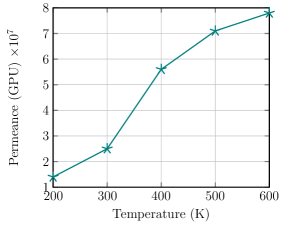
Based on MD simulations, the permeance of \ceH2 molecules can be defined as 63
| (7) |
where and denote the moles of the gas molecules which permeated through the membrane and the area of graphenylene–1 membrane, respectively. Also, is the time duration of the simulations () and the pressure drop () is set to 1 across the pore of the membrane. The permeance of \ceH2 molecule for graphenylene–1 membrane is plotted in FIG. 7. It can be seen that the permeance of \ceH2 molecule enhance with increasing temperature. Moreover, the calculated \ceH2 permeance of graphenylene–1 monolayer together with that of the previously proposed porous membrane at room temperature are summarized in Table 4. As is clear, graphenylene–1 membrane shows an appropriate permeance for \ceH2 gas molecules.
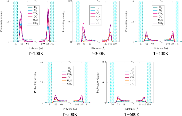
Moreover, the probability density distribution of the gas molecules as a function of distance to graphenylene–1 monolayer plane at different temperature are plotted in FIG. 8. The probability density distribution plots show high adsorption for the gas molecules in the range of 3 to 4 from the sheet at low temperatures and these results confirmed the adsorption height which was reached by DFT calculations. At the higher temperatures, according to increasing the kinetic energy for the gas molecules, they overcome to the adsorption energy and easily desorbed from graphenylene–1 monolayer membrane. Therefore, the probability distribution for each molecule decreases.
4 Conclusion
The most proposed porous membranes for \ceH2 purification and \ceHe separation encounter the selectivity-permenace trade-off problem. On the other hand, many of them were designed just in the theoretical context. So, the study of new membranes for gas separation process seems very necessary.
In this work, we performed DFT calculations and MD simulations to study graphenylene–1 structure, which synthesized by Liu et al. 37, as a monolayer membrane for \ceH2 purification and \ceHe separation. First, the stability of the membrane is confirmed by calculating of the cohesive energy. Then, we demonstrated that \ceH2 and \ceHe molecules can pass through the membrane easily with a surmountable diffusion energy barrier, and , respectively. We showed that the energy barriers of the studied gases (\ceHe, \ceH2, \ceCO2, \ceN2, \ceCO, \ceNe, \ceAr and \ceCH4) passing through graphenylene–1 membrane are directly related to their electron density overlap. Moreover, regarding the energy barriers for the gases, we analyzed the performance of the membrane for the gas separation process. Our results show that graphenylene–1 membrane demonstrate high selectivity for \ceH2 and \ceHe molecules at room temperature which decrease with raising temperature. Also, the permeance of \ceH2 and \ceHe molecules are much higher than the value of them in the current industrial applications at temperatures above and , respectively and enhance with raising temperature. In addition, we demonstrated that all the results based on MD simulations are in perfect agreement with DFT calculations. Consequently, graphenylene–1 monolayer membrane can be an excellent candidate for \ceH2 purification and \ceHe separation since it shows an appropriate balance between the selectivity and the permeance factors.
This work provides an interesting approach to introduce a new membrane for separation of the gases. We believed that graphenylene–1 membrane can be a good target for experimental studies, which is very important in industry.
References
- 1 Winter M. and Brodd R. J., What are batteries, fuel cells, and supercapacitors?, Chemical Review, 2004, 104, 4245-70.
- 2 Andrews J. and Shabani B., Re-envisioning the role of hydrogen in a sustainable energy economy, International Journal of Hydrogen Energy 2012; 37, 1184-203.
- 3 Schlapbach L. and Züttel A., Hydrogen-storage materials for mobile applications, Nature 2001, 414, 353–358.
- 4 Tollefson J., Hydrogen vehicles: fuel of the future? Nature 2010, 464, 1262–1264.
- 5 Turner J. A., Sustainable hydrogen production, Science 2004, 305, 972-4.
- 6 Park H. L., Yi, S. C. and Chung, Y. C., Hydrogen adsorption on Li metal in boron-substituted graphene: an ab initio approach, International Journal of Hydrogen Energy 2010, 35, 3583-84.
- 7 Pen M. A., Gomez J. P. and Fierro J. L. G., New catalytic routes for syngas and hydrogen production, Applied Catalysis A 1996, 144, 7−57.
- 8 Zhu L., Xue Q., Li X., Jin Y., Zheng H., Wu T. and Guo Q., Theoretical prediction of hydrogen separation performance of two- dimensional carbon network of fused pentagon, Applied Materials and Interfaces 2015, 7, 28502−28507.
- 9 Freemantle M., Membranes for gas separation, Chemical and Engineering News 2005, 83, 49−57.
- 10 Oetjen H. F., Schmidt V., Stimming U. and Trila F., Performance data of a proton exchange membrane fuel cell using H2/CO as fuel gas, Journal of the Electrochemical Society 1996, 143, 3838-42.
- 11 Alves H.J., Bley Junior C., Niklevicz R. R., Frigo E. P., Frigo M. S. and Coimbra-Arau´jo C. H., Overview of hydrogen production technologies from biogas and the applications in fuel cells, International Journal of Hydrogen Energy 2013, 38, 5215-25.
- 12 Li F., Qu Y. and Zhao M., Efficient helium separation of graphitic carbon nitride membrane, Carbon 2015, 95 51–7.
- 13 Zhu L., Xue Q., Li X., Wu T., Jin Y. and Xing W., C2N: an excellent two-dimensional monolayer membrane for He separation, Journal of Material Chemistry A 2015, 3, 21351–6.
- 14 Gao G., Jiao Y., Jiao Y., Ma F., Kou .L and Du A., Calculations of helium separation via uniform pores of stanene-based membranes, Beilstein Journal of nanotechnology 2015, 6, 2470–6.
- 15 Nuttall W. J., Clarke R. H. and Glowacki B. A., Resources: stop squandering helium, Nature 2012, 485, 573–5.
- 16 Cho A., Helium-3 shortage could put freeze on low temperature research, Science 2009, 326, 778–9.
- 17 Halperin W. P., The impact of helium shortages on basic research, Nature Physics 2014, 10, 467–470.
- 18 Jiao Y., Du A. and Smith S. C., H2 separation by functionalized graphdiyne-role of nitrogen doping. Journal of Material Chemistry A 2015, 3, 6767-71.
- 19 David E. and Kopac J., Development of palladium/ceramic membranes for hydrogen separation, International Journal of Hydrogen Energy 2011, 36, 4498-4506.
- 20 Deng X., Luo D., Qin C., Qian X. and Yang W., Hydrogen isotopes separation using frontal displacement chromatography with Pd-Al2O3 packed column, International Journal Hydrogen Energy 2012, 37, 10774-8.
- 21 Bernardo P., Drioli E. and Golemme G., Membrane gas separation: a review/state of the art. Industrial and Engineering Chemistry Research 2009, 48, 4638–4663.
- 22 Spillman R. W., Economics of gas separation membranes, Chemical Engineering Progress 1989, 85, 41–62.
- 23 Lin H., Van Wagner E., Freeman B. D., Toy L. G. and Gupta R. P., Plasticization-enhanced hydrogen purification using polymeric membranes, Science 2006, 311, 639-42.
- 24 Herm Z. R., Swisher J. A., Smit B., Krishna R. and Long J. R., Metal organic frameworks as adsorbents for hydrogen purification and precombustion carbon dioxide capture, Journal of American Chemical Society, 2011, 133, 5664-7.
- 25 Chandrasekhar N. and Sholl D. S., Large-scale computational screening of binary intermetallics for membrane-based hydrogen separation. Journal of Physical Chemistry C 2015, 119, 26319-26.
- 26 Li Y., Liang F., Bux H., Yang W. and Caro J., Zeolitic imidazolate framework ZIF-7 based molecular sieve membrane for hydrogen separation, Journal of Membrane Science 2010, 354, 48-54.
- 27 Ji Y., Dong H., Lin H., Zhang L., Hou T., and Li Y., Heptazine-based graphitic carbon nitride as an effective hydrogen purification membrane, RSC Advances 2016, 6, 52377-52383.
- 28 Robeson L. M., Correlation of separation factor versus permeability for polymeric membranes. Journal of Membrane Science 1991, 62, 165-85.
- 29 Robeson L. M., The upper bound revisited. Journal of Membrane Science 2008, 320, 390-400.
- 30 Gao G., Jiao Y., Ma F., Jiao Y., Kou L., Waclawik E., and Du A., Versatile two-dimensional stanene-based membrane for hydrogen purification, International Journal of Hydrogen Energy 2017, 42, 5577-5583.
- 31 Chang X, Xue Q., He D., Zhu L., Li X. and Tao B., 585 divacancy-defective germanene as a hydrogen separation membrane: a DFT study, International Journal of Hydrogen Energy 2017, 42, 24189-24196.
- 32 Kang K. Y., Lee B. I. and Lee J. S., Hydrogen adsorption on nitrogen-doped carbon xerogels, Carbon, 2009, 47, 1171– 1180.
- 33 Giraudet S., Zhu X. H., Yao X. D. and Lu. G. Q., Ordered mesoporous carbons enriched with nitrogen: application to hydrogen storage, Journal of Physical Chemistry C 2010, 114, 8639–8645.
- 34 Jiao Y., Du A., hankel M., Zhu Z., Ruodolph V. and Smith S. C., Graphdiyne: A versatile nanomaterial for electronics and hydrogen purification, Chemical Communications 2011, 47, 11843–11845.
- 35 Schrier J. Fluorinated and nanoporous graphene materials as sorbents for gas separations, ACS Applied Materials and Interfaces 2011, 3, 4451–4458.
- 36 Liu H., Chen Z., Dai S. and Jiang D., Selectivity trend of gas separation through nanoporous graphene, Journal of Solid State Chemistry 2015, 224, 2–6.
- 37 Liu Y., Narita A.,Teyssandier J., Wagner M., De Feyter S., Feng X., and Mullen K., A Shape-persistent polyphenylene spoked wheel, Journal of American Chemical Society 2016, 138, 15539-15542.
- 38 Bartolomei M., Carmona-Novillo E., Hernandez M. I., Campos- Martınez J, Pirani F. and Giorgi G., Graphdiyne pores: Ad Hoc openings for helium separation applications, Journal of Physical Chemistry C 2014, 118, 29966-72.
- 39 Kang J., Wei Z. and Li J., Graphyne and its Family: Recent theoretical advances, ACS Applied Materials and Interfaces 2019, 1, 2692-2706.
- 40 Cranford, S. W. and Buehler, M. J., Selective hydrogen separation through graphdiyne under ambient temperature and pressure. Nanoscale 2012, 4, 4587−4593.
- 41 Zhang H., He X., Zhao M., Zhang M., Zhao L., Feng X. and Luo Y., Tunable hydrogen separation in sp–-sp2 hybridized carbon membranes: a firstprinciples prediction, Journal of Physical Chemistry C 2012, 116, 16634–16638.
- 42 Li C., Li J., Wu F., Li S.-S., Xia J. B. and Wang, L. W., High capacity hydrogen storage in Ca decorated Ggaphyne: a first- principles study, Journal of Physical Chemistry C 2011, 115, 23221−23225.
- 43 Li, Jian-Rong and Kuppler, Ryan J. and Zhou, Hong-Cai, Selective gas adsorption and separation in metal–organic frameworks, The Royal Society of Chemistry 2009, 38, 1477–1504.
- 44 Sang P., Zhao L., Xu. J., Zhi Z., Guo S., Yu Y., Zhu H., Yan Z. and Guo W., Excellent membranes for hydrogen purification: Dumbbell-shaped porous g-graphynes, International Journal of Hydrogen energy 2017, 42, 5168-5176.
- 45 Frisch A., Gaussian 09: user’s reference, Gaussian, Walingford, conn., 2009.
- 46 Tain Z., Dai S., and Jiang D., Expanded porphyrins as two-dimensional porous membranes for CO2 separartion, ACS Applied Materials and Interfaces 2015, 7, 13073-13079.
- 47 Sun H. COMPASS: an Ab initio force-field optimized for condensed-phase applications overview with details on alkane and benzene compounds, Journal of Physical Chemistry B 1998, 102, 7338-64.
- 48 Shan M, Xue Q, Jing N, Ling C, Zhang T, Yan Z, et al. Influence of chemical functionalization on the CO2/N2 separation performance of porous graphene membranes, Nanoscale 2012, 4, 5477-82.
- 49 Wu T, Xue Q, Ling C, Shan M, Liu Z, Tao Y, et al. Fluorinemodified porous graphene as membrane for CO2/N2 separation: molecular dynamic and first-principles simulations, Journal of Physical Chemistry C 2014, 118, 7369-76.
- 50 Xu J, Sang P, Xing W, Shi Z, Zhao L, Guo W, et al. Insights into the H2/CH4 separation through two-dimensional graphene channels: influence of edge functionalization, Nanoscale Research Letters 2015, 10, 492-501.
- 51 Li J, Kuppler R. J., Zhou H. C., Selective gas adsorption and separation in metal–organic frameworks, Chemical Society Review (2009), 38, 1477-1504
- 52 Shekar, S. Chandra and Kumar Meena, Sanjay and Swathi, R. S., Interlocked benzenes in triangular π-architectures: anchoring groups dictate ion binding and transmission, Physical Chemistry Chemical Physics 2017, 16, 10264–10273.
- 53 Treier, Matthias and Pignedoli, Carlo Antonio and Laino, Teodoro and Rieger, Ralph and Müllen, Klaus and Passerone, Daniele and Fasel, Roman, Surface-assisted cyclodehydrogenation provides a synthetic route towards easily processable and chemically tailored nanographenes, Nature Chemistry 2011, 3, 61–67.
- 54 Owais, Cheriyacheruvakkara and James, Anto and John, Chris and Dhali, Rama and Swathi, Rotti Srinivasamurthy, Selective Permeation through One-Atom-Thick Nanoporous Carbon Membranes: Theory Reveals Excellent Design Strategies!, The Journal of Physical Chemistry B 2018, 122, 5127–5146.
- 55 Perim E., Paupitz R., Autreto P. and Galvao D., Inorganic graphenylene: a porous two-dimensional material with tunable band gap, Journal of Physical Chemistry C 2014, 118, 23670e4.
- 56 Li Y., Liao Y. and Chen Z., Be2C Monolayer with quasi-planar hexacoordinate carbons: a global minimum structure, Angew Chem Int Ed 2014, 53, 7248-52.
- 57 Wang Y., Li J., Yang Q., and Zhong C. Two-Dimensional Covalent Triazine Framework Membrane for Helium Separation and Hydrogen Purification, ACS Applied Materials and Interfaces 2016, 8, 8694-8701.
- 58 Hu W., Wu X., Li Z. and Yang J. Helium separation via porous silicene based ultimate membrane. Nanoscale 2013, 5, 9062.
- 59 Blankenburg S., Bieri M., Fase, R., Mllen K., Pignedoli C. A. and Passerone D., Porous graphene as an atmospheric nanofilter. Small 2010, 6, 2266-2271.
- 60 Song Q., Wang B., Deng K., Feng X., Wagner M., Gale J. D., Mllen K. and Zhi L., Graphenylene, a unique two-dimensional carbon network with nondelocalized cyclohex- atriene units. Journal of Material Chemistry C 2013, 1, 38-41.
- 61 Jiang D., Cooper V. R., and Dai S. Porous graphene as the ultimate membrane for gas separation. Nano Letters 2009, 9, 4019-4024.
- 62 Zhu L., Chang X., He D., Xue Q., Xiong Y., Zhang J., Pan X. and Xing, W. Theoretical study of H2 separation performance of two-dimensional graphitic carbon oxide membrane. International Journal of Hydrogen Energy 2017, 42, 13120-13126.
- 63 Du H., Li J., Zhang J., Su G., Li X. and Zhao Y., Separation of hydrogen and nitrogen gases with porous graphene membrane, Journal of Physical Chemistry C 2011, 115, 23261–23266.