Control of transverse motion and X-ray emission of electrons accelerated in laser-driven wakefields by tuning laser spatial chirp
Abstract
A method is proposed to control the transverse motion and X-ray emission of an electron beam in a laser driven wakefield by tuning the laser spatial chirp. The dispersion of a transversely chirped laser pulse and the transverse nonuniform refractive index of the plasma channel result in transverse laser centroid oscillations, which leads to periodic transverse oscillations of the laser-driven wake. Electrons accelerated inside the wake also undergo transverse oscillations making wiggler like motion. Both the oscillation period and amplitude can be controlled by tuning the laser chirp, the pulse duration or the plasma channel width. As a result, the far field spectral distributions of the X-ray emission can be flexibly manipulated.
Keywords: laser wakefield acceleration, laser spatial chirp, betatron radiation, PIC simulation
1 Introduction
Compact x-ray radiation generation is a promising application of laser wakefield acceleration due to the ultra-high accelerating gradient of the wake [1, 2] and the improvement of the beam quality in recent years [3, 4, 5, 6, 7]. Radiation can be generated from the electron betatron oscillations inside the wake or from the interaction of the electron beam with external magnetic or optical wigglers [8, 9, 10, 11, 12, 13, 14, 15, 16, 17].The former is easy for operation but with inflexible tunability both on spectrum and intensity since the oscillation period and amplitude are varying along the beam propagation [8, 18]. The latter is much flexible for radiation tunability, however, the coupling between the electron beam and the wiggler is difficult, and the device is relatively large and costs too much for laboratories in universities and small institutes. Improved schemes were recently investigated by using a plasma channel to induce controllable transverse oscillation of the laser pulse and the wakefield behind the laser driver [19, 20, 21, 22, 23]. In these plasma-based schemes, the usual downstream undulator/wigger part is naturally integrated into the plasma accelerator. Electrons undergo simultaneously longitudinal acceleration and transverse oscillation inside the channel.
Depending on the different ratios between the laser centroid oscillation period () and the electron betatron oscillation period inside the wake (), different radiation enhancement occurs. Lee et al. studied the case where and found that in this case the whole wake oscillation can enhance the oscillation amplitude of the betatron radiation, which leads to higher critical energy of emitted photons [19]. Rykovanov et al. studied the case where and found that in that case the whole wake oscillation can be used as a plasma undulator for fundamental and high order harmonics radiation generation by injecting an electron beam at the point with zero longitudinal wake field [20]. Lei et al. studied the case where and found that the oscillation amplitude can be significantly enhanced when the electron betatron oscillations are in resonance with the laser centroid oscillations, which may extend the radiation spectrum to -ray range [24]. Chen et al. studied the wiggler like synchrotron radiation from the ionization injected electrons in a case with stronger strength parameter [21]. And recently Luo et al. have investigated this in a more general case with three dimensional particle-in-cell (PIC) simulations where they found a helical undulator like radiation with controllable polarization can be generated [22].
The transverse oscillation of an off-axis injected laser pulse in a plasma channel is due to the refractive index gradient depending on the transverse plasma density profile. Here we consider a parabolic plasma channel with electron density distribution , where is the channel depth and is the channel width. The refractive index is a function of the drive laser pulse frequency as , where represents the on-axis plasma frequency and is the frequency of the drive laser pulse. The refractive index is determined by the transverse plasma density distribution, and, if the laser has a transverse spatial chirp, i.e., , there is an additional transverse dependence. The radial dependence of the index of refraction will cause the laser evolution and centroid motion. This paper studies the laser transverse chirp effects on the laser propagation in a plasma channel and the following laser-driven wakefield. The transverse motion and betatron radiation of the electron beams accelerated from such wakefields are investigated as well. We find tunable radiation can be obtained by laser spatial chirp tuning.
2 Transverse laser chirp effects on pulse evolution and centroid oscillation
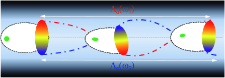
A schematic view of laser pulse evolution and centroid motion is shown in Fig. 1. A laser pulse with normalized electric field of is injected on-axis into a plasma channel, where represents the transverse distance from the axis, is the central frequency of the laser and is a function of space and describes the spatial chirp, , and is the group velocity of the pulse. An unmatched laser pulse propagating inside a plasma channel with a parabolic density profile will experience periodic self-focusing and defocusing. The periodic length is with and , where is the classical electron radius [1]. Since is laser wavelength dependent, the light rays initially at different transverse positions have different color and they will follow different trajectories. For example, the red and blue dashed lines in Fig. 1 show two typical rays of the propagation when the laser pulse has a transverse linear chirp, i.e., , where is a constant representing the spatial chirp degree in the form of normalized frequency gradient. In addition to the trajectory differences, the laser phase velocity is also different, i.e., . Due to these two effects, the pulse will experience transverse deformation and pulse front tilting, which then leads to the laser centroid oscillations. The laser centroid oscillation period satisfies [20, 21, 23, 25].
To investigate these effects on wakefield acceleration, especially the controlled transverse dynamics of the electrons, we use the VLPL particle-in-cell code [26] to model the interaction. In the simulations, a linearly polarized laser pulse with electric field along the direction and normalized electric field intensity of enters into the plasma channel at from the left boundary of the simulation box. The focused radius of the pulse is , where the laser central wavelength is . The on-axis density of the plasma channel is , and . The simulation box has dimensions of and is divided into cells, along and directions, respectively. To observe the laser chirp, the pulse duration and channel width effects on the wakefield acceleration and the beam transverse oscillation, we vary the linear transverse chirp of the pulse (), the duration of the pulse () and the radius of the channel () independently.
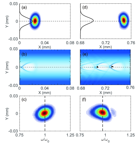
Figure 2 shows a typical simulation with laser transverse chirp of , the pulse duration of , where and plasma channel width of . The initial laser intensity profile and wakefield are shown in Figs. 2(a) and (b), respectively. The laser frequency distribution along direction is shown in Fig. 2(c), obtained by performing a Fourier transformation of the laser electric field along the longitudinal direction (). The dashed black line represents the central frequency. As one can see the pulse initially has a higher frequency component in the top half plane (). The laser and wakefield after propagating about 0.75 mm are shown in Fig. 2(d,e,f). One can see that the transverse centroid of the laser pulse has moved to the top half plane( ), and both the wake and the accelerated electrons inside the buckets have deviated from the channel axis. The transverse laser chirp has rotated its direction (sign), as shown in Fig. 2(c,f), and the central laser frequency has decreased due to the wake excitation, as shown by the black dashed lines. This laser evolution is consistent with the predictions, schematically shown in Fig. 1. The simulation of the laser propagation up to 5 mm exhibits periodic laser pulse oscillation and spectrum rotation.
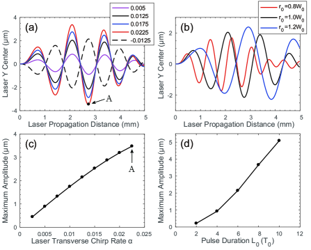
The laser transverse oscillation is tunable when the transverse laser chirp, the pulse duration or the plasma channel radius are varied. In Fig. 3(a), typical transverse laser centroid oscillations resulting from different initial transverse chirps are shown. The initial increasing of the centroid oscillation amplitude during laser propagation, indicating that the optimal chirp profile for maximum oscillation may not be a linear profile. For our linear chirp cases, serial simulations show that the maximum oscillation amplitude is proportional to the spatial chirp rate when is small, as shown in Fig. 3(c). Besides the linear chirp rate, increasing the pulse duration can also enhance the transverse oscillation, which is shown in Fig. 3(d). These studies mean that the beam transverse oscillation amplitude is easily tunable through tuning laser pulse parameters. We should mention that usually the focused width of the laser pulse would vary with the linear spatial chirp as with represents the overall beam width increased from due to spatial chirp and is the full width at half maximum (FWHM) of the pluse duration [27]. In our simulation parameters, which includes little influence in final result. Too large chirp rate will lead to a non-Gaussian pulse, which affects the wake excitation and acceleration. It is out of our interests.
The transverse oscillation period () does not depend on the laser pulse. It is determined by the channel structure as states. The calculated linear period length is approximately mm, and the simulation results show the length of the 3 periods over the 5 mm acceleration distance in Fig. 3(a) are 1.743, 1.342 and 1.239 mm. They are close to the calculated value. The difference is due to the nonlinear effects for and the laser frequency downshift during the propagation. The period depends on the channel width as , and the dependence on is shown in Fig. 3(b). A wider channel with gives a longer oscillation period. The linear value of the wider channel is mm and the two period lengths of the blue solid line in Fig. 3(b) are 2.420 and 1.906 mm. For the case of , the calculated period length is mm, and the first two period lengths of the red solid line in Fig. 3(b) are 1.165 and 0.880 mm. One can also see from Fig. 3(a) that when the sign of the initial chirp has been changed, from to , the initial oscillation direction of the laser centroid changes. After a few periods of propagation, the central laser frequency downshifts, owing to laser energy deposition into the plasma wave, and the spatial chirp is reduced with a reduction in the laser centroid oscillation as well. A more stable oscillation usually needs a longer driver pulse.
3 Transverse laser chirp effects on electron beam oscillation and betatron radiation
Provided the laser oscillation amplitude is not too large, one would expect that the electrons in the wake behind the driver pulse will oscillate following the laser centroid oscillation. To see the relationship between these two kinds of oscillations Fig. 4(a) shows both of the laser and electron beam centroid oscillations for two sets of simulations with different laser transverse chirps and plasma channel widths. The beam has been injected into the wakefield using ionization injection [28, 29, 30]. A short stage of Nitrogen gas with density of 0.0005 and length of 20 is inserted into the beginning of the plasma channel from to with an up-ramp-plateau-down-ramp () profile.
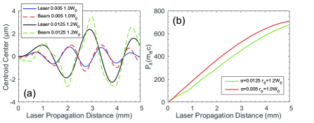
In Fig. 4(a) the solid lines show the laser centroid oscillation and the dashed lines show the corresponding electron beam oscillation. One can see when the laser oscillation amplitude is small (shown by the solid blue line), the electron beam oscillation (shown by the dashed red line) tracks the laser oscillation. The electron beam oscillation includes both the laser centroid oscillation, with period of , and the betatron oscillation, with period of [23]. The latter depends on the energy of the electron beam. When the laser oscillation amplitude increases (shown by the solid black line), the deviation between the electron beam centroid (shown by dashed green line) and the laser centroid increases. Loss of electrons will occur for sufficiently large oscillation amplitude, which usually happens when the transverse spatial chirp is too large. Within our study parameters (), no electron transverse loss has been observed. As one can also see from Fig. 4(b) that larger amplitude oscillations lead to smaller the average acceleration gradient. This would also affect the final radiation spectrum.
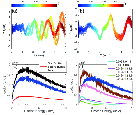
To study the radiation properties of these transversely oscillated electrons, we calculate the radiation spectrum by using a post-processing code VDSR [31]. This code numerically simulates the final spectrum in a way of incoherent radiation addition of the selected electrons whose trajectories are imported from the PIC simulations. We randomly choose 100 electrons trapped by the wake to concentrate on investigating the collective radiation properties due to the limitation of computational resource. The real radiation intensity is proportional to the charge of the injected electrons but the shape of the radiation spectrum does not vary too much, which is demonstrated in a special calculating case where the particle number used for the radiation calculation is doubled. Typical trajectories of randomly selected electrons are shown in Fig. 5(a,b), which correspond to the simulation parameters of and , respectively, with the same laser transverse chirp . In Fig. 5(a), one can clearly see that actually there are two sets of electrons. They come from the first two acceleration bubbles as shown in Fig. 2(e). In the simulation we found that the ratio of the acceleration charge and average gamma factor of the electrons in the first and second bubbles are about 2.5 and 1.3, respectively. The radiation spectra of electrons from the first bubble, the second bubble and both of them are shown in Fig 5(c). Less charge and lower energy of the accelerated electrons in second bubble make their radiation much weaker and tend to lower radiation energy, so in the following radiation tuning studies we only consider the radiation from electrons trapped in the first acceleration bubble.
To avoid the waste of the calculation time on the irregular oscillations and the correspondingly low energy radiation of the accelerated electrons at the beginning of acceleration, we cut off the first long trajectories when we calculate the final radiation spectrum. Radiation spectra from different sets of plasma channel width (), laser transverse chirp parameter () and acceleration distance () are shown in Fig. 5(d). As one can see, both the peak positions and amplitudes of the radiation spectra vary with these parameters. A longer acceleration distance means higher electron energy, which makes the radiation tend to high frequency part and the radiation intensity increase. As we show before, increasing the laser transverse chirp leads to higher transverse oscillation amplitude, which also increases the radiation intensity. A wider channel means a larger trajectory period and corresponds to a lower radiation frequency. All these radiation characters depending on the laser and channel properties are demonstrated in Fig. 5(d). It means in a larger range of photon energy (1-10keV), the spectrum can be flexibly tuned.
4 Summary and discussion
In summary, the control of transverse motion and X-ray emission of electrons accelerated in laser-driven wakefields can be realized by using laser spatial chirp tuning. We noticed that the laser spatial chirp effects on wakefield acceleration in a uniform plasma has been studied experimentally by Popp et al. [32], who found that by tuning the alignment of the grating pair in the laser compressor, the transverse chirp can be tuned. The resulting laser pulse will have a pulse-front tilt during the propagation that can provide electron-beam steering. The introduction of plasma channel in this work enables beam oscillation control. In particular, the effect of laser spatial chirp on laser propagation in a plasma channel has been studied, as well as the effect on beam acceleration in the laser-driven wakefield. Due to the dispersion of the laser pulse along the transverse direction, its different frequency components experience different oscillation trajectories, which causes the laser centroid and the trailing wake to carry out transverse oscillations. The oscillation period can be controlled by tuning the plasma channel parameters and the oscillation amplitude can be tuned by varying the transverse laser chirp. The accelerated beam inside the wake performs similar transverse motion. The mechanism provides a method for controlled x-ray radiation from these oscillating electron beams. Both the peak position and amplitude of the radiation spectrum can be controlled through tuning the above two parameters.
References
References
- [1] Esarey E, Schroeder C B and Leemans W P 2009 Rev. Mod. Phys. 81 1229-85.
- [2] Gonsalves A J et al 2019 Phys. Rev. Lett. 122 084801.
- [3] Wang W T et al 2016 Phys. Rev. Lett. 117 124801.
- [4] Mirzaie M, et al 2015 Sci. Rep. 5 14659.
- [5] Zeng M, Chen M, Yu L L, Mori W B, Sheng Z M, Hidding B, Jaroszynski D A and Zhang J 2015 Phys. Rev. Lett. 114 084801.
- [6] Osterhoff J et al 2008 Phys. Rev. Lett. 101 085002.
- [7] Rechatin C, Faure J, Ben-Ismail A, Lim J, Fitour R, Specka A, Videau H, Tafzi A, Burgy F and Malka V 2009 Phys. Rev. Lett. 102 164801.
- [8] Corde S, Ta Phuoc K, Lambert G, Fitour R, Malka V, Rousse A, Beck A and Lefebvre E 2013 Rev. Mod. Phys. 85 1-48.
- [9] Hooker S M 2013 Nat. Photon. 7 775-82.
- [10] Kneip S et al 2010 Nat. Phys. 6 980-3.
- [11] Schlenvoigt H P et al 2008 Nat. Phys. 4 130-3.
- [12] Fuchs M et al 2009 Nat. Phys. 5 826-9.
- [13] Ta Phuoc K, Corde S, Thaury C, Malka V, Tafzi A, Goddet J P, Shah R C, Sebban S and Rousse A 2012 Nat. Photon. 6 308-11.
- [14] Yi L, Pukhov A, Luu-Thanh P and Shen B 2016 Phys. Rev. Lett. 116 115001.
- [15] Huang K et al 2016 Sci. Rep. 6 27633.
- [16] Yan W et al 2017 Nat. Photon. 11 514-20.
- [17] Wenz J et al 2019 Nat. Photon 13 263-9.
- [18] Esarey E, Shadwick B A, Catravas P and Leemans W P 2002 Phys. Rev. E 65 056505.
- [19] Lee S, Lee T H, Gupta D N, Uhm H S and Suk H 2015 Plasma Phys. Control. Fusion 57 075002.
- [20] Rykovanov S G, Schroeder C B, Esarey E, Geddes C G R and Leemans W P 2015 Phys. Rev. Lett. 14 145003.
- [21] Chen M, Luo J, Li F Y, Liu F, Sheng Z M and Zhang J 2016 Light Sci. Appl. 5 e16015.
- [22] Luo J, Chen M, Zeng M, Vieira J, Yu L L, Weng S M, Silva L O, Jaroszynski D A, Sheng Z M and Zhang J 2016 Sci. Rep. 6 29101.
- [23] Rykovanov S G, Wang J W, Kharin V Y, Lei B, Schroeder C B, Geddes C G R, Esarey E and Leemans W P 2016 Phys. Rev. Accel. Beams 19 090703.
- [24] Lei B F, Wang J W, Kharin V, Zepf M and Rykovanov S 2018 Phys. Rev. Lett. 120 134801.
- [25] Liu M, Deng A, Xia C, Liu J, Wang C, Li R and Xu Z 2010 Opt. Express 18 8077-86.
- [26] Pukhov A 1999 J. Plasma Phys. 61 425-33.
- [27] Akturk S, Gu X, Zeek E and Trebino R 2004 Opt. Express 12 4399-410.
- [28] Chen M, Sheng Z M, Ma Y Y and Zhang J 2006 J. Appl. Phys. 99 056109.
- [29] Pak A, Marsh K A, Martins S F, Lu W, Mori W B and Joshi C 2010 Phys. Rev. Lett. 104 025003.
- [30] Chen M, Esarey E, Schroeder C B, Geddes C G R and Leemans W P 2012 Phys. Plasmas 19 033101.
- [31] Chen M, Esarey E, Geddes C G R, Schroeder C B, Plateau G R, Bulanov S S, Rykovanov S and Leemans W P 2013 Phys. Rev. ST Accel. Beams 16 030701.
- [32] Popp A et al 2010 Phys. Rev. Lett. 105 215001.