Two High-Performance Amplitude Beamforming Schemes for Secure Precise Communication and Jamming with Phase Alignment
Abstract
To severely weaken the eavesdropper’s ability to intercept confidential message (CM), precise jamming (PJ) is proposed by making use of the concept of secure precise wireless transmission (SPWT). Its basic idea is to focus the transmit energy of artificial noise (AN) onto the neighborhood of eavesdropper (Eve) by using random subcarrier selection, directional modulation, phase alignment (PA), and amplitude beamforming (AB). By doing so, Eve will be seriously interfered with AN. Here, the conventional joint optimization of phase and amplitude is converted into two independent phase and amplitude optimization problems. Considering PJ and SPWT require PA, the joint optimization problem reduces to an amplitude optimization problem. Then, two efficient AB schemes are proposed: leakage and maximizing receive power(Max-RP). Simulation results show that the proposed Max-RP and leakage AB methods perform much better than conventional equal AB (EAB) method in terms of both bit-error-rate and secrecy rate at medium and high signal-to-noise ratio regions. The performance difference between the two proposed leakage and Max-RP amplitude beamformers is trivial. Additionally, we also find the fact that all three AB schemes EA, Max-RP, and leakage can form two main peaks of AN and CM around Eve and the desired receiver, respectively.
Index Terms:
Secure precise wireless transmission, precise jamming, phase alignment, secrecy rate, bit error rate.I Introduction
In recent years, physical-layer security (PLS) has received significant attention in establishing secure wireless communications against interceptors[1, 2, 3]. To achieve PLS and improve the secrecy rate (SR), beamforming, artificial noise (AN) and relay cooperation have been incorporated into secrecy network. As a PLS technology, directional modulation (DM) transmits the direction-dependent signals that are normal in the desired directions while disordered in all other directions[4, 5, 6]. Now, DM is widely studied and can be directly applied to millimeter wave and unmanned air vehicle (UAV) communication systems.
However, DM has a limitation in that the beam steering is fixed in an angle for all ranges. To overcome the angle dependence and distance independence characteristics of DM, the authors in [7, 8] proposed secure precise wireless transmission (SPWT) technology which focuses the transmit energy in a desired two-dimensional spatial section. SPWT can be considered as an effective combination of frequency diverse array (FDA) and DM technology. Specially, FDA [9] exploited different frequency offsets to decouple the channels of Bob and Eve, which makes up for the above shortcoming of DM. In [10], the authors optimized the frequency offsets by block successive upper-bound minimization algorithm to ensure the maximum SR of proximal Bob and Eve scenario. To further consider the scenario where Eve is sensitive enough, the authors in [11] made full use of AN to achieve a higher SR. Moreover, the authors extended the frequency offset optimization investigation in the case of multiple eavesdroppers. Different from frequency offset optimization to maximize SR, the authors in [12] studied the SPWT in the orthogonal frequency diversion multiplexing (OFDM) wireless communication system, where the subcarrier index was highly randomized by integer mod, ordering and block interleaving. With the assistance of singular value decomposition (SVD), a multi-beam DM scheme based on multi-carrier FDA was proposed, which reduces both implementing complexity and power consumption[13].
Although beamforming schemes have been investigated intensively, almost all of the previous studies design the amplitude and phase simultaneously. In this letter, we propose a novel beamforming scheme for a communication system of PJ with artificial noise based on random-subcarrier-selection (RSS-PJ-AN), our main contributions in this paper are as follows:
-
1.
To focus the AN energy on Eve, we extend the idea of SPWT to a precise jamming (PJ). By doing so, Eve will be degraded seriously. To achieve both SPWT and PJ, phase alignment (PA) is mandatory for the beamforming vectors of CM and AN. Then, a novel beamforming framework is proposed for SPWT and PJ. In other words, the beamforming design is decomposed into two parts: PA and amplitude beamforming (AB).
-
2.
Using the proposed new beamforming framework, two AB schemes are proposed: leakage and maximum receive power (Max-RP). Both AB of AN and CM are based on the two rules. Simulation results show that, compared to equal AB (EAB), the proposed two AB schemes leakage and Max-RP perform better in the medium and high signal-to-noise ratio (SNR) regions in terms of SR and bit-error-rate (BER) performance while they have the same performance as EAB in the low SNR region.
The remainder of this paper is organized as follows. In Section II, we describe RSS-PJ-AN system model. Subsequently, we propose two AB methods: leakage-based and Max-RP in Section III. In Section IV, the performance of the proposed scheme is numerically evaluated, and conclusions are given in Section V.
Notations: matrices, vectors, and scalars are denoted by letters of bold upper case, bold lower case, and lower case, respectively. Signs , and denote matrix transpose, conjugate transpose and Moore-Penrose inverse, respectively. returns the diagonal concatenation. The operation denotes modulus of a complex number. The symbol denotes the identity matrix.
II System Model
Fig. 1 illustrates a typical architecture for RSS-PJ-AN system model consisting of an -antenna uniform linear transmit array, a single-antenna Bob and a single-antenna Eve. CM is transmitted towards Bob via randomly-selected multiple subcarriers from all-subcarrier set of OFDM. The all-subcarrier set of OFDM is , where is the carrier frequency and is the subchannel bandwidth. The subcarrier assigned to -th antenna is , where [8].
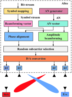
In this work, we assume that the channels between transmitter and receivers are LoP ones. The normalized steering vector for the transmit antenna array is given by
| (1) |
where with being element spacing of uniform linear array (ULA) and being light speed. and are the direction angle and distance from Alice to receiver. Normally, frequency increment and carrier frequency can satisfy . It is assumed that Bob and Eve are located at and with a high-resolution direction of arrival estimation [14], respectively.
The baseband transmit signal can be expressed as
| (2) |
where is the CM and is the AN both with average power constraint (i.e., , ). is the transmit power of Alice and is the parameter that determines the power allocation between the CM and AN. and are the normalized CM beamforming vector and the normalized AN vector, respectively.
Considering that SPWT and PJ require to align with Bob () and to align with Eve (), the n-th element of phase vector of and can be expressed as and , respectively. Here, we define and , where and are both diagonal matrix as and , respectively. Meanwhile, is the AB vector of and is the AB vector (i.e., and ). Accordingly, the received signal at Bob and Eve can be formulated as follows
| (3) |
and
| (4) |
where and are the additive white Gaussian noise (AWGN), distributed as and , respectively. and denote path loss coefficients from Alice to Bob and from Alice to Eve, respectively. is the reference distance which is set to 1m.
In what follows, for the convenience of optimization, and are relaxed as complex optimization variables, and the corresponding element magnitudes of vectors and are set to be the element magnitudes of optimal and in terms of some rules.
III Two Proposed AB Schemes
In this section, to improve the SR performance, two AB schemes leakage and Max-RP with EAB methods are proposed to optimize the amplitude parts of the beamforming vectors of AN and CM. Here, their phase parts are directly set to the negation of phases of channel steering vectors in order to form the main peaks of CM and AN at Bob and Eve, respectively.
III-A Proposed Leakage-Based AB Method
Making use of leakage criterion, we use the maximizing signal-to-leakage-noise ratio (Max-SLNR) method to optimize the vector , which can be obtained as
| (5) | ||||
where
| (6) |
which yields the vector being the eigenvector corresponding to the largest eigenvalue of matrix
| (7) |
Since is a complex vector, the magnitude of element of vector is chosen to be . Next, the AN is viewed as the useful signal of Eve. Let be the optimization vector, similarly, we have
| (8) | ||||
where
| (9) |
which results in the optimal value of being the generalized eigenvector corresponding to the largest normalized eigenvalue of matrix
| (10) |
Likewise, the AB vector of is taken to be .
III-B Proposed Max-RP-based AB Method
Now, we turn to a new rule. By maximizing the receive power of CM at Bob, the AB part of are constructed. The corresponding optimization problem of Max-RP is given by
| (11) | ||||
where the constraint forces CM to transmit on the null space of . To address the above problem, the singular-value decomposition (SVD) of is computed as , where is a complex number, and consists of the last right singular vectors corresponding to zero singular values. Define , and , then the optimization problem in (11) is converted into
| (12) | ||||
which means that is the eigenvector corresponding to the largest eigenvalue of matrix . The design of has been finished. Then, the AB vector of is .
IV Simulations and Discussions
In our simulation, system parameters are set as follows: quadrature phase shift keying (QPSK) modulation, the total signal bandwidth is 5MHz, = 3GHz, the number of total subcarriers , , , , , and .
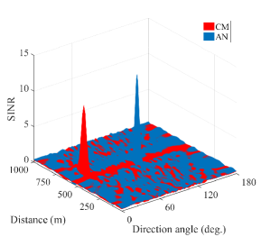
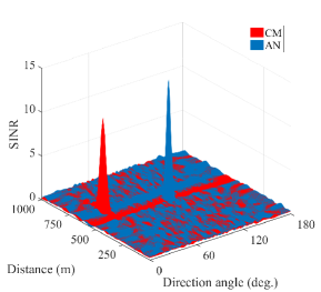

Fig. 2 plots the three-dimensional (3D) performance surface of signal-to-interference-plus-noise ratio (SINR) versus direction angle and distance of proposed methods for SNR = 14dB, where the conventional EAB method is used as a performance reference. Here, CM is a useful signal for Bob, and AN is a useful signal for Eve. Observing three parts in Fig. 2, two peaks of CM and AN are only around Bob and Eve , respectively. Additionally, we also find a fact that the main peaks of Bob and Eve of the proposed methods are much higher than those of EAB, which means that the proposed methods have a better SINR performance.
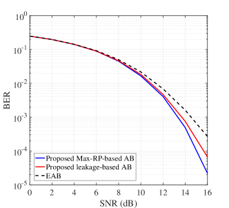
Fig. 3 shows the curves of BER versus the SNR, for the two proposed AB schemes described in Section-III. The figure illustrates that our proposed methods outperform the EAB. Particularly in the high SNR region, the BER performance of our proposed schemes is about one order of magnitude, better than that of the EAB method.
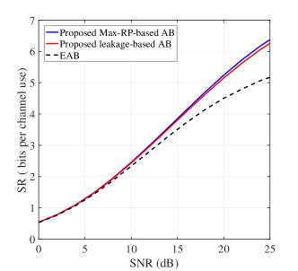
In what follows, we also evaluate the performance of the proposed AB schemes from SR aspect. Fig. 4 demonstrates the curves of SR versus SNR of the proposed AB methods. From Fig. 4, it is noted that the SR performance of the three method are close to each other in the low SNR region. As SNR grows, the performance gap between the proposed schemes and EAB method becomes larger, which greatly improves the security of communication system.
V Conclusion
In this paper, we mainly proposed two high-performance AB schemes: leakage and Max-RP to enhance the PLS of wireless communication. Simulation results showed that our proposed two AB schemes behaved better than EAB method in terms of BER and SR.
References
- [1] A. D. Wyner, “The wire-tap channel,” Bell. Syst. Tech. J., vol. 54, no. 8, pp. 1355–1387, Oct. 1975.
- [2] Y. Wu, J. Wang, J. Wang, R. Schober, and C. Xiao, “Secure transmission with large numbers of antennas and finite alphabet inputs,” IEEE Trans. Commun., vol. 65, no. 8, pp. 3614–3628, Aug. 2017.
- [3] J. Ma, S. Zhang, H. Li, N. Zhao, and V. C. M. Leung, “Interference-alignment and soft-space-reuse based cooperative transmission for multi-cell massive MIMO networks,” IEEE Trans. Wireless Commun., vol. 17, no. 3, pp. 1907–1922, Mar. 2018.
- [4] Y. Ding and V. F. Fusco, “A vector approach for the analysis and synthesis of directional modulation transmitters,” IEEE Trans. Antennas Propag., vol. 62, no. 1, pp. 361–370, Jan. 2014.
- [5] J. Hu, F. Shu, and J. Li, “Robust synthesis method for secure directional modulation with imperfect direction angle,” IEEE Commun. Lett., vol. 20, no. 6, pp. 1084–1087, 2016.
- [6] F. Shu, X. Wu, J. Li, R. Chen, and B. Vucetic, “Robust synthesis scheme for secure multi-beam directional modulation in broadcasting systems,” IEEE Access, vol. 4, pp. 6614–6623, 2016.
- [7] J. Hu, S. Yan, F. Shu, J. Wang, J. Li, and Y. Zhang, “Artificial-noise-aided secure transmission with directional modulation based on random frequency diverse arrays,” IEEE Access, vol. 5, pp. 1658–1667, 2017.
- [8] F. Shu, X. Wu, J. Hu, J. Li, R. Chen, and J. Wang, “Secure and precise wireless transmission for random-subcarrier-selection-based directional modulation transmit antenna array,” IEEE J. Sel. Areas Commun., vol. 36, no. 4, pp. 890–904, Apr. 2018.
- [9] P. Antonik, M. C. Wicks, H. D. Griffiths, and C. J. Baker, “Frequency diverse array radars,” in 2006 IEEE Radar Conf., Apr. 2006, pp. 3 pp.–.
- [10] J. Lin, Q. Li, J. Yang, H. Shao, and W. Wang, “Physical-layer security for proximal legitimate user and eavesdropper: A frequency diverse array beamforming approach,” IEEE Trans. Inf. Forensics Security, vol. 13, no. 3, pp. 671–684, Mar. 2018.
- [11] B. Qiu, J. Xie, L. Wang, and Y. Wang, “Artificial-noise-aided secure transmission for proximal legitimate user and eavesdropper based on frequency diverse arrays,” IEEE Access, vol. 6, pp. 52 531–52 543, 2018.
- [12] T. Shen, S. Zhang, J. Wang, J. Hu, F. Shu, and J. Wang, “Two practical random-subcarrier-selection methods for secure precise wireless transmissions,” IEEE Trans. Veh. Technol., pp. 1–1, 2019.
- [13] Q. Cheng, V. Fusco, J. Zhu, S. Wang, and C. Gu, “SVD-aided multi-beam directional modulation scheme based on frequency diverse array,” IEEE Wireless Commun. Lett., pp. 1–1, 2019.
- [14] F. Shu, Y. Qin, T. Liu, L. Gui, Y. Zhang, J. Li, and Z. Han, “Low-complexity and high-resolution DOA estimation for hybrid analog and digital massive MIMO receive array,” IEEE Trans. Commun., vol. 66, no. 6, pp. 2487–2501, Jun. 2018.