Spectral control over -ray echo using a nuclear frequency comb system
Abstract
Two kinds of spectral control over -ray echo using a nuclear frequency comb system are theoretically investigated. A nuclear frequency comb system is composed of multiple nuclear targets under magnetization (hyperfine splitting), mechanical motion (Doppler shift) or both, namely, moving and magnetized targets. In frequency domain the unperturbed single absorption line of -ray therefore splits into multiple lines with equal spacing and becomes a nuclear frequency comb structure. We introduce spectral shaping and dynamical splitting to the frequency comb structure respectively to optimize the use of a medium and to break the theoretical maximum of echo efficiency, i.e., 54%. Spectral shaping scheme leads to the reduction of required sample resonant thickness for achieving high echo efficiency of especially a broadband input. Dynamical splitting method significantly advances the echo efficiency up to 67% revealed by two equivalent nuclear frequency comb systems. We also show that using only few targets is enough to obtain good echo performance, which significantly eases the complexity of implementation. Our results extend quantum optics to 10keV regime and lay the foundation of the development of -ray memory.
The -ray-nuclear interfaces are recently demonstrated to be interesting for fundamental physics in the development of -ray/X-ray quantum optics Adams et al. (2013), which explores a completely new energy realm of light-matter interactions van Bürck et al. (1987); Kocharovskaya et al. (1999); Kuznetsova et al. (2003); Bürvenich et al. (2006); Vagizov et al. (2009); Röhlsberger et al. (2010); Liao et al. (2011); Röhlsberger et al. (2012); Liao et al. (2013); Heeg et al. (2013, 2015a); Radeonychev et al. (2015); Liao et al. (2016); Haber et al. (2017); Khairulin et al. (2018). Pursuing coherent control over -rays is also expected to be versatile for applications Vagizov et al. (2014); Liao and Pálffy (2014); Liao and Ahrens (2015); Heeg et al. (2015b, 2017); Liao and Pálffy (2017); Wang and Liao (2018). E.g., spectral control over -rays may lead to new light source for Mössbauer spectroscopy Heeg et al. (2017). Given the sub-angstrom wavelength of -photon, it avoids the bottleneck of diffraction limit for photonic information processing Liao et al. (2012); Vagizov et al. (2014), e.g., -photon storage Shvyd’ko et al. (1996); Liao et al. (2012); Kong and Pálffy (2016); Zhang et al. (2018). -ray echo Helistö et al. (1991); Helistö and Tittonen (2001) is shown to be a valuable and practical method for shaping -ray wavepacket Vagizov et al. (2014) and forming nuclear quantum memory Zhang et al. (2018). In this letter, we put forward spectral shaping and dynamical splitting to manipulate the recently proposed nuclear frequency comb (NFC) Zhang et al. (2018) and its resulting -ray echo. The former is used to optimize the echo efficiency, and the latter is intended for beating the theoretically maximum echo efficiency of 54% Sangouard et al. (2007); Zhang et al. (2018). In view of the success of the optical echo memory Sangouard et al. (2007); Moiseev and Arslanov (2008); Hétet et al. (2008); Tittel et al. (2010); Zhang et al. (2014); Liao et al. (2014); Su et al. (2017) based on atomic frequency comb (AFC) Afzelius et al. (2009); Zhou et al. (2012), our scheme gives an importnat step for the development of future -ray echo memory Zhang et al. (2018). Moreover, the present results suggest applications such as a -ray coherent delay line providing an input -ray pulse with a tunable time delay, and the generation of time-bin qubit for single quanta.
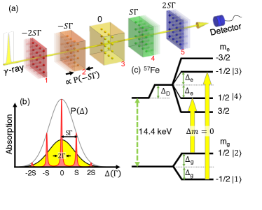
We begin with the optimization of a NFC using spectral shaping. Figure 1(a) illustrates our modified NFC system by introducing a resonant thickness distribution function to a sequence of targets. The spatial order of the comb teeth does not matter. The energy shift from the unperturbed transition energy can be generated by, e.g., Doppler shift, and the afterimage of each cuboid depicts its motion with a constant velocity Zhang et al. (2018). The coloured cuboids represent targets where embedded nuclei experience different . With a proper arrangement, multiple absorption peaks can form a NFC with a tunable comb spacing . Here is the spontaneous decay rate of some chosen excited states, and . Red, orange, yellow, green and blue are respectively for , , zero, and . The yellow short pulse depicts the incident -ray. Since the absorption strength is proportional to resonant thickness, modifies the overall NFC in the frequency domain as depicted in Fig. 1(b). The black-solid-yellow-filled line demonstrates the spectrum of the incident -ray pulse. In view that the input spectral intensity on resonance with unperturbed transition is stronger than those at side bands, can properly match the overall NFC (multiple red-solid-filled peaks) with the input spectrum such that the use of whole medium is optimal. This will ease the demand of very high resonant thickness for achieving high echo efficiency in a flat comb Zhang et al. (2018).
Figure 1(c) shows the level scheme of 57Fe nucleus with hyperfine splitting and Doppler shift . Without Doppler shift, i.e., , multiple magnetized and stationary targets can also form a NFC when , and each target contributes a pair of comb tooth for a linearly polarized -ray. For the sake of simplicity we term the case when both and as hybrid shift. The Maxwell-Bloch equation for the th target in perturbation regime Scully and Zubairy (2006); Liao et al. (2012, 2014); Kong et al. (2014), namely, , describes the coupling between nuclei and -ray:
| (1) | |||||
| (2) | |||||
| (3) |
Together with initial conditions , and the input boundary condition . Other boundary conditions are , i.e., we treat the output from th target as the input of th target. Here and are the slowly varying amplitudes of the coherence term in the density matrix of the level scheme illustrated in Fig. 1(c). is the slowly varying amplitudes of the Rabi frequency of the linearly polarized -ray propagating through th target, and represents the speed of light. Above mentioned is generalized for 57Fe nuclear hyperfine structure. Energy shift of transition and are respectively and . The coupling constant , where GHz is the spontaneous decay rate of excited states and , the resonant thickness and the thickness of th target. is the corresponding Clebsch-Gordan coefficient for two transitions in Fig. 1(c). For flat NFC, a Fourier analysis Zhang et al. (2016, 2018) of Eq. (1-3) shows that the echo efficiency where is the average resonant thickness over total targets. Temporal domain contains only echo signal which peaks at . The theoretical maximum is 54% when and approach infinity as also predicted by typical echo memory system limited by re-absorption Sangouard et al. (2007); Zhang et al. (2016). While the required target parameters are not realistic for , we would like to address the question of how to achieve reasonably high with an optimization of resonant thickness? As a reference a flat comb with (, ) = (50, 8) results in .
In order to match NFC and the spectrum of an input Gaussian pulse, we let proportional to a normalized Gaussian distribution
| (4) |
where the total target number odd. This spectral shaping can be achieved by controlling either the isotope concentration or the target thickness during crystal growth. The modified comb structure in Fig. 1(b) is given by multiplying the flat comb Zhang et al. (2018) and , where parameter is used to adjust the overall width of NFC, e.g., for a flat comb and for a NFC width equals to the bandwidth of the incident pulse. The analytical solution of the output signal due to spectral shaping reads (see Supplementary Material for derivation)
| (5) |
where is the total resonant thickness, and the introduced must be long enough to cover the complete output signal.
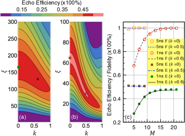
The consistency between Eq. (5) and numerical solution has been carefully checked (see Supplementary Material). Fig. 2 shows the (, )-dependent echo efficiency based in Eq. (5) and demonstrates the general effect of spectral shaping technique. An unperturbed single target can be utilized to control only a tiny Fourier fraction of a broadband input pulse whose bandwidth is much larger than the natural linewidth of the absorber. The use of very high may ease the broadband difficulty but will degrade due to dispersion Liao et al. (2014). Spectral shaping technique in NFC will lower the needed and provides a solution to above problem. In Fig. 2(a) we demonstrate a broadband echo efficiency by using (, , ) = (1ns, 50, 21), i.e., an input bandwidth of 141. It plainly exhibits, on one hand, the -dependent improvement of , e.g., is prominently raised from 30% to 44% when = 1 is introduced for . On the other hand, the -induced reduction of needed for achieving some can be observed for all contours. Fig. 2(b) shows another prominent example for (, , ) = (5ns, 50, 9), namely, a narrower input bandwidth of 28. The required for significantly decreases from 60 for to 26 for . One can see that -modified NFC not only preserves the echo performance but also offers the advantage of the reduction of required . Comparing shaped NFC with flat comb, maximum 22% and 53% reduction of are observed for ns and ns, respectively, whose parameters are indicated by green dot, black cross, brown-filled square and blue cross in Fig. 2(a) and Fig. 2(b). The -modified NFC therefore optimizes the use of resonant thickness in contrast to a flat comb. In view of Fig. 1(b), of a narrow band input is mainly determined by the central resonant line and side bands, because the spectral intensity of incident photons in this range is high. Including high order side bands mainly leads to even higher because more frequency components are involved in the re-phasing process. One can therefore remove targets contributing side bands with negligible change in . Along this line, in Fig. 2(c) we discuss the reduction of target number via finding maximum in the domain of for each , and calculate the corresponding fidelity Chen et al. (2013); Liao et al. (2014); Zhang et al. (2018), where
Brown-filled squares and green dots respectively depict -dependent maximum for ns and for ns using flat comb (). Orange squares and red circles are their fidelity. The 5ns echo performance already reaches and as . However, more targets () are needed for ns to achieve and due to its larger bandwidth than both and comb spacing. To manifest the advantage of spectral shaping technique, we show another set of and for ns using with black-solid line and black-dashed line, respectively. For ns, blue-dotted line and blue-dashed-dotted line respectively illustrate and using . It deserves to emphasize the versatile potential of spectral shaping technique with which one can essentially engineer to cooperate with the input spectrum or to get desired output echo signals.
We now turn to address the issue of how to achieve . In a stationary comb system, is mainly restricted by the re-absorption during phase revival and pulse propagation Sangouard et al. (2007); Zhang et al. (2018). It is therefore critical to find a way to ease the re-absorption of emitted photons. For this we invoke the dynamical splitting of NFC illustrated in Fig. 3(a). Initially, four targets are stationary. Magnetic field (blue upward arrows) is applied to only targets a1 and a2 (green cuboids) whose nuclei experience hyperfine splitting . Targets a3 and a4 (yellow cuboids) are not magnetized and contribute unperturbed resonance to NFC. Fig. 3(c) illustrates the initial absorption peaks at zero and induced by constant hyperfine splitting. Subsequently, targets a1 and a3 (a2 and a4) are backward (forward) accelerated and experience corresponding time-dependent Doppler shift . The total energy shift results from both mechanical acceleration and magnetic field, namely, hybrid shift, is described by and , where Here describes the raising time of the target velocity and is the middle time of the acceleration. , , or respectively depicts the forward acceleration (red Doppler shift), stationary or backward acceleration (blue Doppler shift). For a given comb spacing , the terminal velocity of an accelerated target where is the unperturbed transition angular frequency, and during the period of a NFC tooth at is moving to . Fig. 3(d) depicts the NFC evolution due to above-mentioned time sequence. The contributors to each line are labelled, e.g., the top green-dashed-bent-upward line is given by target a1 in Fig. 3(a) and by target b1 in Fig. 3(b). Each NFC line splitting originates from a corresponding pair of targets under opposite acceleration.
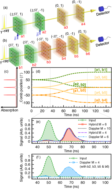
Alternatively, as illustrated in Fig. 3(b), one can invoke pure mechanical motion with to equivalently construct above dynamical splitting of NFC. is given by the initial velocity of each target, and is also introduced by acceleration. Green, orange and yellow cuboid respectively demonstrate target with , and zero.
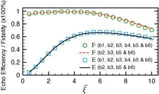
Three purposes of utilizing are (i) the absorption of the incident pulse can be enhanced by the part of comb teeth drifting inward the central resonant line; (ii) the comb is modulated so that the re-absorption condition is avoided during the whole emission process because emitters become off-resonant to re-absorbers due to time-dependent Doppler shift. Also, the input photons are distributed in different target depending on their frequency. The dynamical comb is therefore an analogy to gradient echo memory (GEM) Hétet et al. (2008); (iii) the frequency crossing at around 60ns corresponds to the reversing of the spatial gradient and causes the echo emission Hétet et al. (2008). With the numerical solution of Eq. (1-3) (see Supplementary Material for numerical method), Fig. 3(e) demonstrates the echo signal due to above dynamical NFC system illustrated in Fig. 3(d). An optimization of shows that is significantly raised to 67% with for an input 7ns pulse (green-dashed-filled line) when using (, ) = (60ns, 100ns). Four cases are presented by red-solid-filled line for hybrid shift and [six targets with , , , , and ]; by black-dotted line for Doppler shift and [ten targets with , , , , , , , , and ]; by purple-long-dashed line for hybrid shift and illustrated in Fig. 3(a); by blue-short-dashed-dotted-dotted line for Doppler shift and depicted in Fig. 3(b). Other parameters are (, , , ) = (7ns, 50, 0, 4.83mm/s), for hybrid shift and for pure Doppler shift. One can perceive the equivalence of two systems by seeing the coincidence of both echo signals. We also use a 5ns pulse as an input and obtain and . In the light of above purpose (iii) and Fig. 3(d), target b1 and b4 should contribute very limited fraction to the echo. As depicted in Fig. 3(f), we remove target b1 and b4 from the system of Fig. 3(b) and get an echo signal with and for a 7ns input pulse, which is very close to what we show in Fig. 3(e). Fig. 4 shows the comparison of -dependent and between with and without target b1 and b4 in Fig. 3(b). The consistency suggests the analogy between our dynamical comb and GEM. However, its inhomogenous energy broadening is implemented by temporal variation rather than by only spatial gradient. This distinction allows dynamical splitting scheme using only few targets to achieve comparing to our previous proposal of stepwise GEM Zhang et al. (2018), and significantly reduces the complexity of implementation.
The dynamical splitting method can be applied to other wavelength region and provides a general way to achieve higher echo efficiency than the theoretical maximum Sangouard et al. (2007); Zhang et al. (2018). As depicted in Fig. 3(d), each target is accelerated to few mm/s within 100ns for the implementation of the present scheme. This is feasible Zhang et al. (2018) because reversing velocity in an even shorter interval of about 10ns had be demonstrated Helistö et al. (1991); Tittonen et al. (1993); Shakhmuratov et al. (2011, 2013). Moreover, controllable few ns -ray source generating incident pulse had be demonstrated Vagizov et al. (2014) and proposed Wang and Liao (2018).
In conclusion we have demonstrated two types of spectral control over -ray echo, which break the theoretical maximum echo efficiency of 54% Sangouard et al. (2007); Zhang et al. (2018). Our results lay the foundation of developing -ray photon memory in 10keV regime Zhang et al. (2018). The present scheme also suggests a -ray echo device providing tunable time delay, which is typically difficult by using exquisite -ray optics.
C.-J. Y., P.-H. Lin and W.-T. L. are supported by the Ministry of Science and Technology, Taiwan (Grant No. MOST 107-2112-M-008-007-MY3 and Grant No. MOST 107-2745-M-007-001-). W.-T. L. is also supported by the National Center for Theoretical Sciences, Taiwan.
References
- Adams et al. (2013) B. W. Adams, C. Buth, S. M. Cavaletto, J. Evers, Z. Harman, C. H. Keitel, A. Pálffy, A. Picón, R. Röhlsberger, Y. Rostovtsev, et al., Journal of modern optics 60, 2 (2013).
- van Bürck et al. (1987) U. van Bürck, R. L. Mössbauer, E. Gerdau, R. Rüffer, R. Hollatz, G. V. Smirnov, and J. P. Hannon, Phys. Rev. Lett. 59, 355 (1987).
- Kocharovskaya et al. (1999) O. Kocharovskaya, R. Kolesov, and Y. Rostovtsev, Phys. Rev. Lett. 82, 3593 (1999).
- Kuznetsova et al. (2003) E. Kuznetsova, R. Kolesov, and O. Kocharovskaya, Phys. Rev. A 68, 043825 (2003).
- Bürvenich et al. (2006) T. J. Bürvenich, J. Evers, and C. H. Keitel, Phys. Rev. Lett. 96, 142501 (2006).
- Vagizov et al. (2009) F. Vagizov, R. Manapov, E. Sadykov, V. Lyubimov, and O. Kocharovskaya, Hyperfine Interactions 188, 143 (2009).
- Röhlsberger et al. (2010) R. Röhlsberger, K. Schlage, B. Sahoo, S. Couet, and R. Rüffer, Science 328, 1248 (2010).
- Liao et al. (2011) W.-T. Liao, A. Pálffy, and C. H. Keitel, Physics Letters B 705, 134 (2011).
- Röhlsberger et al. (2012) R. Röhlsberger, H. C. Wille, K. Schlage, and B. Sahoo, Nature 482, 199 (2012).
- Liao et al. (2013) W.-T. Liao, A. Pálffy, and C. H. Keitel, Phys. Rev. C 87, 054609 (2013).
- Heeg et al. (2013) K. P. Heeg, H.-C. Wille, K. Schlage, T. Guryeva, D. Schumacher, I. Uschmann, K. S. Schulze, B. Marx, T. Kämpfer, G. G. Paulus, et al., Phys. Rev. Lett. 111, 073601 (2013).
- Heeg et al. (2015a) K. P. Heeg, J. Haber, D. Schumacher, L. Bocklage, H.-C. Wille, K. S. Schulze, R. Loetzsch, I. Uschmann, G. G. Paulus, R. Rüffer, et al., Phys. Rev. Lett. 114, 203601 (2015a).
- Radeonychev et al. (2015) Y. V. Radeonychev, V. A. Antonov, F. G. Vagizov, R. N. Shakhmuratov, and O. Kocharovskaya, Phys. Rev. A 92, 043808 (2015).
- Liao et al. (2016) W.-T. Liao, C. H. Keitel, and A. Pálffy, Scientific reports 6, 33361 (2016).
- Haber et al. (2017) J. Haber, X. Kong, C. Strohm, S. Willing, J. Gollwitzer, L. Bocklage, R. Rüffer, A. Pálffy, and R. Röhlsberger, Nature Photonics 11, 720 (2017).
- Khairulin et al. (2018) I. R. Khairulin, V. A. Antonov, Y. V. Radeonychev, and O. Kocharovskaya, Phys. Rev. A 98, 043860 (2018).
- Vagizov et al. (2014) F. Vagizov, V. Antonov, Y. Radeonychev, R. Shakhmuratov, and O. Kocharovskaya, Nature 508, 80 (2014).
- Liao and Pálffy (2014) W.-T. Liao and A. Pálffy, Phys. Rev. Lett. 112, 057401 (2014).
- Liao and Ahrens (2015) W.-T. Liao and S. Ahrens, Nature Photon. 9, 169 (2015).
- Heeg et al. (2015b) K. P. Heeg, C. Ott, D. Schumacher, H.-C. Wille, R. Röhlsberger, T. Pfeifer, and J. Evers, Phys. Rev. Lett. 114, 207401 (2015b).
- Heeg et al. (2017) K. P. Heeg, A. Kaldun, C. Strohm, P. Reiser, C. Ott, R. Subramanian, D. Lentrodt, J. Haber, H.-C. Wille, S. Goerttler, et al., Science 357, 375 (2017).
- Liao and Pálffy (2017) W.-T. Liao and A. Pálffy, Scientific Reports 7, 321 (2017).
- Wang and Liao (2018) G.-Y. Wang and W.-T. Liao, Phys. Rev. Applied 10, 014003 (2018).
- Liao et al. (2012) W.-T. Liao, A. Pálffy, and C. H. Keitel, Phys. Rev. Lett. 109, 197403 (2012).
- Shvyd’ko et al. (1996) Y. V. Shvyd’ko, T. Hertrich, U. van Bürck, E. Gerdau, O. Leupold, J. Metge, H. D. Rüter, S. Schwendy, G. V. Smirnov, W. Potzel, et al., Phys. Rev. Lett. 77, 3232 (1996).
- Kong and Pálffy (2016) X. Kong and A. Pálffy, Phys. Rev. Lett. 116, 197402 (2016).
- Zhang et al. (2018) X. Zhang, W.-T. Liao, A. Kalachev, R. Shakhmuratov, M. Scully, and O. Kocharovskaya, arXiv preprint arXiv:1812.11441 (2018).
- Helistö et al. (1991) P. Helistö, I. Tittonen, M. Lippmaa, and T. Katila, Phys. Rev. Lett. 66, 2037 (1991).
- Helistö and Tittonen (2001) P. Helistö and I. Tittonen, Hyperfine interactions 135, 167 (2001).
- Sangouard et al. (2007) N. Sangouard, C. Simon, M. Afzelius, and N. Gisin, Phys. Rev. A 75, 032327 (2007).
- Moiseev and Arslanov (2008) S. A. Moiseev and N. M. Arslanov, Phys. Rev. A 78, 023803 (2008).
- Hétet et al. (2008) G. Hétet, J. J. Longdell, M. J. Sellars, P. K. Lam, and B. C. Buchler, Phys. Rev. Lett. 101, 203601 (2008).
- Tittel et al. (2010) W. Tittel, M. Afzelius, T. Chaneliere, R. L. Cone, S. Kröll, S. A. Moiseev, and M. Sellars, Laser & Photonics Reviews 4, 244 (2010).
- Zhang et al. (2014) X. Zhang, A. Kalachev, and O. Kocharovskaya, Phys. Rev. A 90, 052322 (2014).
- Liao et al. (2014) W.-T. Liao, C. H. Keitel, and A. Pálffy, Phys. Rev. Lett. 113, 123602 (2014).
- Su et al. (2017) S.-W. Su, S.-C. Gou, L. Y. Chew, Y.-Y. Chang, I. A. Yu, A. Kalachev, and W.-T. Liao, Phys. Rev. A 95, 061805 (2017).
- Afzelius et al. (2009) M. Afzelius, C. Simon, H. de Riedmatten, and N. Gisin, Phys. Rev. A 79, 052329 (2009).
- Zhou et al. (2012) Z.-Q. Zhou, W.-B. Lin, M. Yang, C.-F. Li, and G.-C. Guo, Phys. Rev. Lett. 108, 190505 (2012).
- Scully and Zubairy (2006) M. O. Scully and M. S. Zubairy, Quantum Optics (Cambridge University Press, 2006).
- Kong et al. (2014) X. Kong, W.-T. Liao, and A. Pálffy, New Journal of Physics 16, 013049 (2014).
- Zhang et al. (2016) X. Zhang, A. Kalachev, P. Hemmer, and O. Kocharovskaya, arXiv preprint arXiv:1602.02322 (2016).
- Chen et al. (2013) Y.-H. Chen, M.-J. Lee, I.-C. Wang, S. Du, Y.-F. Chen, Y.-C. Chen, and I. A. Yu, Phys. Rev. Lett. 110, 083601 (2013).
- Tittonen et al. (1993) I. Tittonen, M. Lippmaa, P. Helistö, and T. Katila, Phys. Rev. B 47, 7840 (1993).
- Shakhmuratov et al. (2011) R. N. Shakhmuratov, F. Vagizov, and O. Kocharovskaya, Phys. Rev. A 84, 043820 (2011).
- Shakhmuratov et al. (2013) R. N. Shakhmuratov, F. Vagizov, and O. Kocharovskaya, Phys. Rev. A 87, 013807 (2013).