Reconfiguration Algorithms for High Precision Communications in Time Sensitive Networks: Time-Aware Shaper Configuration with IEEE 802.1Qcc (Extended Version) ††thanks: Please direct correspondence to M. Reisslein (reisslein@asu.edu).
Abstract
As new networking paradigms emerge for different networking applications, e.g., cyber-physical systems, and different services are handled under a converged data link technology, e.g., Ethernet, certain applications with mission critical traffic cannot coexist on the same physical networking infrastructure using traditional Ethernet packet-switched networking protocols. The IEEE 802.1Q Time Sensitive Networking (TSN) task group is developing protocol standards to provide deterministic properties on Ethernet based packet-switched networks. In particular, the IEEE 802.1Qcc, centralized management and control, and the IEEE 802.1Qbv, Time-Aware Shaper, can be used to manage and control scheduled traffic streams with periodic properties along with best-effort traffic on the same network infrastructure. In this paper, we investigate the effects of using the IEEE 802.1Qcc management protocol to accurately and precisely configure TAS enabled switches (with transmission windows governed by gate control lists (GCLs) with gate control entries (GCEs)) ensuring ultra-low latency, zero packet loss, and minimal jitter for scheduled TSN traffic. We examine both a centralized network/distributed user model (hybrid model) and a fully-distributed (decentralized) 802.1Qcc model on a typical industrial control network with the goal of maximizing scheduled traffic streams.
Index Terms:
Low-latency traffic, Protocol adaptation, Reconfiguration, Time Sensitive Networking (TSN).I Introduction
I-A Motivation
I-A1 Centralized User/Distributed (Hybrid) Model
IEEE 802.1 Time Sensitive Networking (TSN) provides a standardized framework of tools for providing deterministic ultra-low latency (ULL), e.g., for industrial control applications, automotive networking, and avionics communication systems [1, 2]. In particular, the IEEE 802.1Qbv Time Aware Shaper (TAS) has received extensive attention as a key tool for achieving deterministic ULL network service. The TAS operation requires careful planning of the synchronized time cycles and the gate times that are allocated to the scheduled traffic (ST) and the unscheduled best effort traffic (BE). The TAS parameter settings specifying the timing characteristics (cycle time, gate slot allocations) are also commonly referred to as the Qbv schedule or the TAS schedule. For a given static networking scenario, the TAS operation with a properly configured Qbv schedule can ensure the deterministic ULL required by demanding industrial and automotive applications [3].
Modern network scenarios often involve dynamic changes with varied use cases, such as changes in the network nodes and network topology, or the traffic pattern. For instance, nodes or links may be dynamically added or removed. Or, nodes may inject additional traffic flows or traffic flows may terminate, or the latency requirements of flows may change dynamically. Such dynamic changes have been included in the use cases defined by IEC/IEEE 802.1 TSN TG [4].
In a typical industrial environment, sensors that periodically or sometimes sporadically send ambient measurements to a local gateway require certain Quality of Service (QoS) guarantees. In such a volatile and dynamic environment, new machinery that requires prioritized execution (e.g., emergency cooling procedures or maintenance tasks for network traffic tests) may be brought onto the factory floor. To deal with such scenarios, the Time-Aware Shaper (TAS) Gate Control Lists (GCLs) in coordination with the Network Management Entities (NMEs), e.g., Centralized Network Configuration (CNC), has to adapt to changing environment conditions by judiciously applying reconfiguration such that stream deadlines, QoS, and total stream utilization times (reported by a stream registration procedure) are satisfied.
Similarly, in a disaster management networking scenario, a network may have physically lost large amounts of network resources (links and routes) but needs to manage the flows that are currently present. A central orchestrator can prudently time share the reserved resources such that a large number of streams can be completely serviced, i.e., the total execution time for each stream is completed by the network.
Generally, in such dynamic networking scenarios, applying only admission control will clearly guarantee (in accordance with a traffic shaper) the QoS metrics (of the admitted flows). However, for a given static network configuration, the total number of admissible streams may be well below the number of streams that seek network service. Therefore, adding a dynamic reconfiguration strategy to manage and configure the network appears to be a plausible and attractive solution that intuitively should lower capital and operational expenditures as it mitigates the over-provisioning of network resources. The general idea for such an allocation scheme is to control network access in a timely and orderly fashion such that a maximum number of streams can be effectively serviced.
Our objective therefore is to maximize the number of admitted flows (i.e., tasks or streams) in such a dynamically changing and volatile environment whilst keeping the TSN QoS metric guarantees. To the best of our knowledge there are no prior detailed studies on a dynamic stream resource allocation and admission control policy in conjunction with a network reconfiguration policy being executed while flows are carried in a TAS time scheduled network. In this paper, we focus on the IEEE 802.1Qbv [5] enhancements and design a reconfiguration framework taking inspiration from the IEEE 802.1Qcc [6] standards for managing, configuring, and reconfiguring a TSN network.
I-A2 Decentralized Model
The IEEE 802.1Qcc standard specifies three models for configuring the Time-Aware Shaper (TAS) gating schedules (GCL/GCE timing computation): a fully-centralized model, a centralized network/distributed user model (hybrid model, see Section I-A1), and a fully-distributed configuration model. The centralized model greatly eases control and configuration messages sent across the network and can precisely configure TAS schedules due to having complete knowledge of the network and full capabilities of each bridge. However the centralized model suffers from common disadvantages, such as a single-point of failure, relatively large capital/operational (CapEx/OpEx) expenditures (as the centralized control may be superfluous in a small-scale network [7]), and adding unnecessary complexity to a small-scale network. Thus, a fully-distributed configuration model (e.g., SRP over MRP or RAP over LRP) may be attractive for some networks. The fully-distributed configuration model avoids the added complexity and single point of failure of a centralized management entity. Moreover, Chen et al. [7] have argued that the centralized configuration models can be an over-design for real-time applications with relaxed latency requirement (order of magnitude of milliseconds). Chen et al. have also argued that the distributed model is more scalable. (However, studies of the fully distributed model with RAP over LRP targeted typically applications with relatively relaxed latency requirements.)
In the absence of a Centralized Network Configuration (CNC) node, the TSN Task Group (TG) specifies the IEEE 802.1CS (Link-Local Registration Protocol, LRP) [8] standard for registration and distribution of application configuration parameters between point-to-point links targeting newly published TSN features. A legacy protocol, such as the Stream Reservation Protocol (SRP) [9] which is primarily used for AVB application, is intended to serve as the main resource reservation and admission control protocol. However, extending and porting the SRP to be utilized for bridges that support TAS will not suffice since bandwidth reservation cannot directly apply TAS’s time slot reservation natively. Therefore, the Resource Allocation Protocol, IEEE 802.1Qdd (RAP) [7], has been proposed to apply a distributed resource reservation that can exchange TSN features.
In our model, the switch computes the TAS time slot for all admitted streams as follows. In the absence of admission control, we predefine the TAS slot to be a minimum of 10% and a maximum of 90% of the Cycle Time (CT), even when no streams are registered, so as to avoid starvation of Best Effort (BE) traffic. With admission control, the static predefinition, which can potentially waste resources if unused, can be eliminated. Essentially, as streams get registered, we keep track of the remaining load on each egress port until the load (which depends on the slot size and CT) is negative (oversubscribed link). Such a link over-subscription invokes a procedure call that increases the slot time (by a step size of 1%, or more fine-grained increments) until the remaining load is positive. This procedure is iteratively called until all registered streams and the new stream are appropriately registered with sufficient Scheduled Traffic (ST) slot time to transmit all frames during a single appropriately sized CT. Note that the TAS time slot is defined as the portion of the CT that is allocated to high-priority ST traffic.
Our proposed TAS configuration/reconfiguration, is designed for the fully-distributed configuration model. In the distributed approach, the GCE slot parameters are configured in a distributed manner by the switches as per the distributed algorithm/procedure explained in Sec. IV. In the centralized approach, the GCE slot parameters are configured centrally by the CNC with the Centralized User Configuration (CUC) node assisting in passing end-station (source/sink, devices, etc.) capabilities and parameters. Similarly, the “hybrid” model also utilizes the CNC for configuration exchange and network side management (see Section I-A1).
Regarding the differences between the hybrid model and the fully centralized model, the main network-side difference is the way the User/Network configuration Information (UNI) is propagated. In the fully centralized model, the sources communicate Control Data Traffic (CDT) messages to/from the CUC node, instead of having each source interact directly with the CNC. According to the 802.1Qcc standard, the general advantage is that the computation complexity (especially for industrial/automotive applications with computationally complex I/O timing requiring detailed knowledge of the application’s software/hardware within each end station) can be tolerated by having the CUC handle end station discovery, retrieving end station capabilities and user requirements, and configuring TSN features in end stations. The CNC is used to only manage and configure network side components. In terms of benefits, the configuration delay is potentially reduced, scheduling optimality increased, and hardware performance overhead/complexity reduced with a shorter network response time for networks involving command and control systems. The development and investigation of a reconfiguration approach for the fully centralized configuration model is left as future work.
Our study focuses on the centralized network/distributed user model (hybrid model) and the fully-distributed (decentralized) configuration model. For brevity we refer to the centralized network/distributed user model (hybrid model) also as the centralized model or the centralized topology. We refer to the fully-distributed (decentralized) model also as the decentralized model or the decentralized topology.
Our proposed TAS reconfiguration architecture maps and propagates stream information and conducts dynamic TAS time slot reservations (including GCL/GCE scheduling and provisioning) on local shared stream database records to guarantee TSN QoS for all admitted streams and to maximize stream admission using a reconfiguration strategy of TAS gating schedules within each bridge in a fully decentralized IEEE 802.1Qcc model.
I-B Related Work
Raagaard et al. [10] presents a heuristic algorithm that reconfigures TAS switches according to runtime network conditions. Feasible schedules are produced and forwarded using a configuration agent (composed of a Centralized User Configuration (CUC) and Centralized Network Configuration (CNC)). Raagaard et al’s model places emphasis on appearing and disappearing synthetic flows in a fog computing platform that takes into account the flow’s properties and possible routes. Contrary to this approach our framework performs flow maximization with optimal reconfiguration based on firm bandwidth computation strategies at run-time. Further, we show the equilibrium point for this algorithm.
I-C Contributions
We comprehensively evaluate the performance of TAS for reconfigurations in the hybrid and fully distributed models with respect to network deployment parameters, such as, maximum window size for the Gate Control List (GCL) repetition, gating ratio proportion, i.e., Gate Control Entry (GCE) proportion, to control delay perceived at the receiving end, signaling impact on Scheduled Traffic (ST) and Best-Effort traffic (BE) classes, and packet loss rate experienced at the receiving end. In particular, we make the following contributions:
-
i)
We design a CNC interface for a TSN network to globally manage and configure TSN streams, including admission control and resource reservation.
-
ii)
We integrate the CNC in the control plane with TAS in the data plane to centrally manage and shape traffic using the CNC as the central processing entity for flow schedules as more flows are added.
-
iii)
We modify and test the model to operate in a distributed fashion, i.e., the control and data planes are combined.
-
iv)
We evaluate each design approach and for a range of numbers of streams and sources with different TAS parameters. We show results based on admission ratios, network signaling overhead, and QoS metrics.
I-D Organization
This article is organized as follows. Section II provides background information and an overview of related work on the 802.1 TSN standardization, focusing on the enhancements to scheduled traffic and centralized management and configuration. Section III shows the complete top-down design of the CNC (hybrid model) and main components that achieve ultra-low latencies and guaranteed QoS for a multitude of ST streams. Similarly, Section IV shows the approach used in implementing the decentralized (fully distributed) TAS reconfiguration model. The simulation setup as well as main parameters and assumptions are given in Section V and results are presented in Sections V-B and V-C. Finally conclusions and future work are outlined in Section VI.
II Background: IEEE 802.1 Time Sensitive Networking
II-A IEEE 802.1Qbv: Time Aware Shaper (TAS)
TAS’s main operation is to schedule critical traffic streams in reserved time-triggered windows. In order to prevent lower priority traffic, e.g., best effort (BE) traffic, from interfering with the scheduled traffic (ST) transmissions, ST windows are preceded by a so-called guard band. TAS is applicable for Ultra Low Latency (ULL) requirements but needs to have all time-triggered windows synchronized, i.e., all bridges from sender to receiver must be synchronized in time. TAS utilizes a gate driver mechanism that opens/closes according to a known and agreed upon time schedule for each port in a bridge. In particular, the Gate Control List (GCL) represents Gate Control Entries (GCEs), i.e., a sequence of on and off time periods that represent whether a queue is eligible to transmit or not.
The frames of a given egress queue are eligible for transmission according to the GCL, which is synchronized in time through the 802.1AS time reference. Frames are transmitted according to the GCL/GCE and transmission selection decisions. Each individual software queue has its own transmission selection algorithm, e.g., strict priority queuing. Overall, the IEEE 802.1Qbv transmission selection transmits a frame from a given queue with an open gate if: The queue contains a frame ready for transmission, higher priority traffic class queues with an open gate do not have a frame to transmit, and the frame transmission can be completed before the gate closes for the given queue. Note that these transmission selection conditions ensure that low-priority traffic is allowed to start transmission only if the transmission will be completed by the start of the scheduled traffic window for high-priority traffic. Thus, this transmission selection effectively enforces a “guard band” to prevent low-priority traffic from interfering with high-priority traffic [1].
II-B IEEE 802.1Qcc: Centralized Management and Configuration
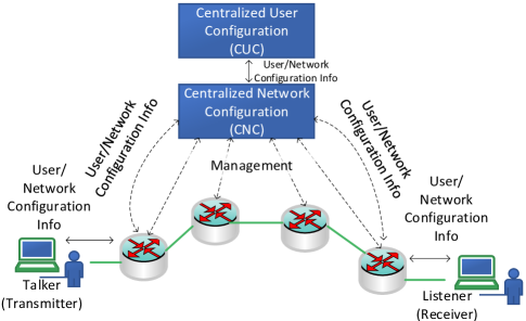
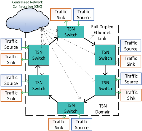
IEEE 802.1Qcc [6] provides a set of tools to globally manage and control the network. In particular, IEEE 802.1Qcc enhances the existing Stream Reservation Protocol (SRP) with a User Network Interface (UNI) which is supplemented by a Centralized Network Configuration (CNC) node, as shown in Fig. 1. The UNI provides a common method of requesting layer 2 services. Furthermore, the CNC interacts with the UNI to provide a centralized means for performing resource reservation, scheduling, and other types of configuration via a remote management protocol, such as NETCONF [18] or RESTCONF [19]; hence, 802.1Qcc is compatible with the IETF YANG/NETCONF data modeling language.
III Centralized Model Design and Framework Considerations
This section presents our design methodology and main signaling framework for the centralized network/distributed user model (hybrid model). Our main goals behind designing the CNC is given by the following constraints. Additionally, the CNC can be logically or physically connected to the data-plane with in-band or out-of-band management links.
-
1.
Our focus is mainly on stream based network adaptation. By this technique, fluctuating streams (already registered streams and new incoming streams) and their requirements can be accommodated by the network dynamically based on a single remote procedure call to the CNC.
-
2.
Identify and execute flow requirements by populating the registration table. The control plane resource orchestration is purely carried out by the monitoring of existing flows which have been satisfied.
-
3.
Optimizing resource allocation (maximize admitted streams/flows) based on a bounded latency and network utilization, i.e., prioritize flows that request low network resources.
Our main assumption to accurately apply admission control and, consequently, reconfiguration, is that each source must define a flow in terms of total resources needed (governed by the bandwidth requirements) and the total time needed for the resource to be used (which in our traffic model is termed as the resource utilization time). Essentially, the CNC uses this information (which is tagged in the Ethernet frame header) to determine whether a frame is admitted or rejected.
III-A Core Components
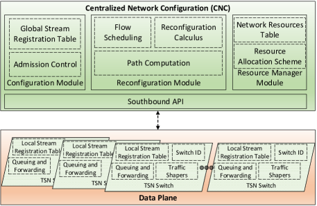
Our design is split into two layers, Control Plane and Data Plane, following the decoupling SDN paradigm, thereby inheriting the benefits of the orthogonality of the two planes, as shown in Fig. 2.
III-A1 Configuration Module
The configuration module is the main component that interacts with the registered flows and network components. It includes the global stream registration table which records all approved stream transmitting in the network, and the admission control element that encapsulates and decapsulates CDT headers and forwards the information to the necessary module/element.
Global Stream Registration Table
The source streams (devices/users) make a Remote Procedural Call (RPC) via the stream registration interface for providing information that can be mapped as a unique tuple structure identification . Upon receiving the registration packet, i.e., Control Data Traffic (CDT), the CNC determines whether the new stream can be accepted in its stream table. To guarantee the QoS for all registered streams, admission control principles are applied to all streams according to the stream’s path, required network resources, and available resources.
Admission Control
The admission control element is the first element that the new streams interacts with. The admission control element under the configuration module globally manages all streams transmitting in the TSN domain governed by the CNC. The admission control element extracts the necessary information from the CDT packet and forwards the information according to the CDT type. The CNC apples several steps to decide whether to accept or reject the stream transmission request.
-
1.
The CNC checks the destination address(es) of the stream and consults its resource manager module for network resources available on the new stream’s path, which is computed based on the path computation element within the CNC.
-
2.
According to the bandwidth required for the new stream (calculated at the bridge gateway for the new stream), all links on the path are checked to see if enough bandwidth is available for the new stream.
-
3.
In the event that not enough resources are available, the CNC applies the TAS reconfiguration module to identify the bottleneck link(s) and to check whether the gating ratio can be increased for that specific traffic class whose current resource utilization and deadline will not cause a late deadline by being added to the TAS slot reservation.
III-A2 Reconfiguration Module
The reconfiguration module includes the flow scheduling element (for our network model, the Time-Aware Shaper (TAS) is used in the data plane), the reconfiguration calculus element which optimizes flow registration according to each stream’s total resource utilization and flow deadlines, and finally the path computation element which defines the path for all stream according to the QoS constraint.
Flow Scheduling
The flow scheduling element currently takes the Time-Aware Shaper into consideration. Due to the TAS’s requirements on time synchronization between network components (switches, hosts, etc.), the CNC follows the same principle of scheduling flows according to a known timescale (initially set to be 50 s in our network model). The CNC then passes on this time synchronization information to the TSN enabled switches within its domain. Any approved streams will transmit frames according to the time scale specified by the flow scheduler in the CNC.
Reconfiguration Calculus
In addition to centrally managing resources and providing admission control policies to the network, the CNC can invoke the TAS reconfiguration strategy with the goal of borrowing BE time slots for pending ST traffic streams. This element consults the resource manager module on the bottleneck link and checks whether the added stream will oversubscribe the link. The TAS reconfiguration incrementally (1% of total CT) increases the traffic class slot time and reserves it for the new stream.
Path Computation
For large scale and complex LAN/MAN topologies, it is often required to supplement streams with equal cost paths in the event of a path disruption (e.g., link failure, stream saturation, and explicit congestion). The CNC’s path computation element is tasked with finding such paths as a fail-over approach to avoid any violations to any stream’s QoS. Presently, our model has a rudimentary application of path computation, i.e., it is defined statically for all core network components (shortest path), since the main emphasis was on reconfiguration based on stream characteristics as defined by the source.
III-A3 Resource Manager Module
The resource manager module centrally manages all network resources within the CNC’s domain. It includes the network resource table that records all streams’ usage of resources, and the resource allocation scheme element to which we delegate the task of calculating the required network resources for a given stream according to an allocation scheme.
Network Resource Table
To remove certain overheads on the configuration module, the network resource table operates in tandem with the global stream registration table to accurately determine the required network resources (mainly bandwidth for our traffic model). It classifies streams based on periodic stream properties. Any stream that has been approved by the CNC has a record attached to it in the network resource table.
Resource Allocation Scheme
Several allocation schemes can be implemented for all traffic classes defined in the network. For periodic streams, the time slot given by the flow scheduler (according to the TAS Cycle Time and number of traffic classes) and the data rate defined by the source is used to calculate the required bandwidth for each link on the path to the destination (i.e., sink).
III-A4 Data Plane
The data plane contains all core switches. Any TSN switch interfaced by the CNC is given a switch ID and has a local stream registration table. The remaining switch elements compose the forwarding and queuing operation with several traffic shapers (802.1Qbv TAS in our network model).
Local Stream Registration Table
This data plane registry contains the subset of source streams that are established for the corresponding bridge gateway and attached sources to each port. The CNC delegates some control to the bridge gateway to instruct and alert sources of any new network conditions and explicit changes.
Traffic Shaper — Time-Aware Shaper
The traffic shaper is the main shaping and scheduling mechanism that controls the gating schedules for all the traffic classes within the TSN domain. All bridges are synchronized to the same gating schedule GCL Cycle Time (CT) given by the CNC’s flow schedule element (CT indicates the time period for the GCL to repeat).
IV Decentralized Model Design and Framework Considerations
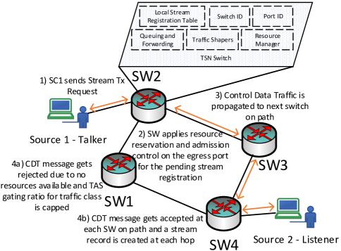
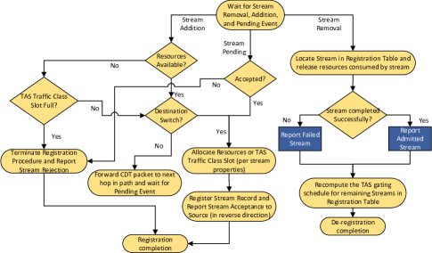
This section presents our design methodology and framework for the TAS reconfiguration in the decentralized (fully distributed) model. Our current proposed architecture generally follows the steps enumerated below and illustrated in Fig. 3. Our description focuses on the additions to the design of RAP over LRP, e.g., TAS slot computation/reservations.
-
1.
At each egress port (Port Identifier, PID), the TSN switch maintains a local stream registration table that includes information, such as flow ID, gateway (i.e., the first bridge that a talker is connected to), destination address(es), the traffic injection rate per GCL cycle time, and the calculated port bandwidth requirement. The traffic injection rate is not computed, rather the traffic injection rate is reported by the source (talker) to the network devices. It mainly indicates the bandwidth requirements of a stream. Bandwidth for a bridge egress port needed for a stream is computed using the ST injection rate (or ST rate), the average packet size, and the bridge TAS timing configuration (e.g., the CT and current traffic class slot time). This information is carried and communicated between bridges using the CDT packet type identifier (or message type).
-
2.
A source (talker) can send a stream transmission request, i.e., a CDT message of type Stream Transmission Request to register its stream and use the TSN service for scheduled traffic.
-
3.
Each switch maintains a resource manager module for each port. If the newly incoming stream is accepted (due to available resources and TAS slot space). The TAS slot size for a specific traffic class is governed by the CT and traffic class gating ratio (in time). The TAS ST slot can be configured/reconfigured according to stream requests and terminations. The stream registration message is then propagated towards the next switch, and a map is maintained for the stream (and any other streams) pending approval.
-
4.
If accepted by the last switch, then the stream registration record is added to the local stream registration table, and bandwidth resources are allocated for the stream and TAS slot space is modified (if necessary) on the reverse path. The main reason for allocating the resources in the reverse path is as follows. If we allocate the resources in the forward direction but a switch in the next hop rejects the stream (due to lack of resources), then we have to release the resources reserved earlier for the stream. Therefore, we avoid the allocation until all hops provide assurance that the stream will be accommodated.
-
5.
Each switch receiving the pending registration message adds the stream record to its local table, allocates the necessary resources and TAS slot reservation, and propagates the registration message towards the source gateway.
-
6.
The source gateway receives the pending stream registration message and similarly allocates the resources and finally sends an approval granted message towards the source which prompts the source to start sending data in the next available TAS cycle.
While the previous enumerated points provide an overview of the procedural approach used, a key question remains, namely what happens if frames belonging to a given stream arrive after the gate for it’s traffic class queue has been closed? Generally, the way the stream traffic end station (source/talker) operates is by synchronizing to the switch’s TAS ST slot time for the class the stream belongs to (in our case, it is ST) after the CDT stream registration is complete. Therefore, it will always send data traffic at the beginning of the ST slot. After the data traffic for the ST stream arrives at the first switch (where the gate for the ST queue will definitely be open due to source-network synchronization), the new ST traffic is queued at the back of the queue awaiting transmission. Since registration and resource allocation for all ST streams is enforced, the computed ST slot size will be large enough to transmit all ST packets (from all streams being serviced through that specific switch’s egress port) queued that arrived from different sources during the cycle time. The delay bounds (a data traffic stream arriving before a specific time and not necessarily at the right time) is guaranteed since the cycle time for each switch along the path is configured to be large enough to transmit all ST frames registered on the multi hop path (up to 5 hops). Some potential ST traffic sent on cycle time can be transmitted at cycle time , but would be blocked by some subsequent slots in the first cycle time belonging to different traffic classes (in our case, it is BE) leading to higher delays but still within tolerated delays since the cycle time is usually much smaller than the max delay bounds or threshold defined (e.g., 50 microseconds cycle time and 100 microseconds delay bounds).
In our simplified example in Fig. 3, each switch, upon initialization and with admission control, provisions all the CT to BE traffic. When the first stream transmission request occurs, the switches exchange the CDT message and start building the local stream registration table. A switch builds the GCE slot time for ST by mapping each stream request to its internal stream registration table upon granting the stream approval. The switch builds the ST slot time iteratively by following each stream admission/termination. The switch passes each set of stream configuration parameters (UNI) through the 802.1Qcc registration and reservation protocol.
ST traffic stream load is viewed in two main ways in our implementation. ST injection rate, and resource utilization time. The ST injection rate corresponds to the number of packets sent from an ST stream in one TAS cycle time, while the resource utilization time is the time that the stream reports to the network on how long the resources reserved will be used. The bandwidth requirement for a new stream request is calculated by taking the reported ST injection rate of the stream and multiplying that with the packet size for the stream. That quantity is then divided by the TAS slot time (at a specific switch). Essentially, an increase in the slot time corresponds to a decrease in the bandwidth requirement (since more time is given) and vice versa. Note that this only works for streams with periodic data transmissions and not for sporadic data streams since we cannot calculate how much time is needed for a sporadic data transmission. This procedure is only for ST traffic; BE traffic is transmitted with the leftover slot time after the ST traffic has been serviced.
IV-A Core Components
This section outlines the main components required to successfully implement stream admission control and resource reservation within switches that support the TAS traffic shaper in a distributed fashion. Fig. 4 illustrates the typical registration/reservation procedure for all streams within the TSN domain.
IV-A1 Admission Control
The admission control element extracts the necessary information from the CDT packet and forwards the information according to the CDT type. The switch forwarding mechanism applies several steps to accurately decide whether to accept or reject the stream transmission request Note that the stream transmission request corresponds to a CDT message. In particular, the switch consults the resource manager module to check if enough resources (bandwidth) is available for the new stream that is calculated by the reported traffic injection rate, the maximum cycle time, and the traffic class’s TAS slot time. A given stream’s bandwidth requirement is calculated by multiplying the ST injection rate with the average packet size and dividing by the current ST slot size. Note that the traffic class TAS slot time is the time during which the TAS gate is open to transmit frames belonging to the considered class. Also note that all GCEs are executed during each CT. If the CT is smaller than the aggregate of the GCEs, then we need to either increase the CT or reject streams that cause the exceedance of the CT.
IV-A2 Flow Scheduling
This element currently takes the Time-Aware Shaper into consideration. Due to the TAS’s requirements on time synchronization between network components (switches, hosts, etc.), all switches/hosts follow the TAS GCL timescale cycle time (e.g., 50 s). Depending on the number of traffic classes supported, the TAS cycle time can be divided into appropriate slots for each traffic class load. The TAS CT is divided among all the traffic classes (in our evaluation model, we consider two traffic classes, BE and ST). Currently, in our evaluations, the CT is initially predefined to 50 microseconds. Note that the CT could be changed/configured dynamically. The dynamic adaptation of the CT with respect to new stream additions, application specifications, or other events is a topic for future work.
IV-A3 Stream Registration Table
Stream creation follows a Poisson process with a mean duration. Different scenarios with varying mean duration enables analysis of how reconfiguration works in multiple settings. The stream life-time is defined by the duration. For example, how the switches in the path are aware of the Poisson parameter from the edge switch. All GCE entries and Queues are based purely on this slots allocated based on the Poisson parameter. Although, our approach does not intend to minimize delay, we follow a delay bound strategy that leads to finding the limiting value. Implicitly, the limiting value can be minimized that can provide a minimized delay. Additionally, the stream registration table contains the characteristics of the source streams that are established for the corresponding bridge egress port. Each record gets populated (if accepted) on the reverse path taken by the stream’s registration message (after reaching the destination switch).
IV-A4 Traffic Shaper - Time-Aware Shaper
The main shaping and scheduling mechanism that controls the gating schedules for all the traffic classes within the TSN domain. All bridges are synchronized to the same gating schedule GCL CT that is initially predefined by network administrator. Ideally, we want the CT to be large enough for all streams from all traffic classes to be accommodated and small enough that the all streams QoS fits the delay requirements. In our current evaluations, the CT is predefined at the widely used 50 microseconds.
IV-A5 Reconfiguration Calculus
In essence, the reconfiguration (dynamic configuration) of the TAS schedules (switch GCL/GCE) for each egress port is dynamically invoked according to two principle events, adding a new stream, and removing an existing stream. The switch’s gating ratio (for a particular stream belonging to a defined traffic class) reports certain parameters (e.g., packet injection rate, maximum packet size, latency requirement, deadline, application response time, etc.) which are then used to check if enough slot time is available (which corresponds to attempting bandwidth reservation). In the event that no slots are available, the GCE slot size is recomputed (according to the registered stream properties within the registration table) generally by allocating more resources from Best Effort Traffic. The stream life time is reported by the source to the network as user/network information (UNI). Each UNI is propagated by each switch along the path which allows the switch to register the stream and store the stream’s resource utilization time, (stream life-time), among other critical information. Any information pertaining to the UNI of a stream is recorded in the stream registration table. In terms of GCEs for TAS with support of ST and BE traffic classes, only two GCEs within a GCL (1/0 (ST/BE) for the first entry and 0/1 (BE/ST) for the second) are necessary with a total of three outbound queues for each egress channel port in a TSN switch. Two queues for each traffic class, and another queue for CDT traffic (signaling traffic). Upon initialization, each switch allocates resources to ST, and BE therefore gets all the leftover CT slot. As streams get registered, the ST slot time is recomputed (according to the stream packet size, ST injection rate, and current slot time, if the slot exists). If the stream is the first stream to the switch, i.e., ST slot is , then the ST slot size is defined to be 1% of the CT at a minimum by borrowing necessary time slot from BE.
IV-A6 Path Computation
While this module is fundamentally necessary in any switch (in a decentralized/distributed network), we manually define static routing tables for destination addresses and associated ports on each switch. Essentially, we assume a manual procedure to compute paths, i.e., we assume that there is a path computation module that is used in both centralized and distributed configuration models. We make this assumption to simplify operations and place emphasis on the TAS reconfiguration technique.
IV-A7 Network Resource Table
To remove certain overheads on the configuration procedure, the network resource table operates in tandem with the stream registration table to accurately determine the required network resources (mainly bandwidth for our traffic model) per switch egress port. It classifies streams based on periodic and sporadic streams properties, though currently the focus is on periodic ST streams. Any approved stream by the switch has a record attached to it in the network resource table, located within each switch, which can be called to compute and store current and remaining link/port loads for each switch. Each egress port has a network resource table. More details on the network resource table will be provided in the next iteration of this document.
V Performance Evaluation
V-A System Overview and Simulation Setup
This section explains the simulation setup and model. Furthermore, the topology and simulation scenarios will be presented. Throughout, we employ the OMNet++ [21] simulation environment.
| Key | Symbol | Value |
|---|---|---|
| Simulation Duration | seconds | |
| Initialized Cycle Time | s | |
| Initialized Gating Ratio | % (i.e., 10 s) | |
| Average Streams per Second | ||
| Average stream duration | seconds | |
| Number of Frames per Cycle | ||
| BE Traffic Intensity | (low, mid, and high) | |
| ST sources | ||
| Hurst Parameter | ||
| Queue Size | Kb |
| Hops # | 1 | 2 | 3 | 4 | 5 |
|---|---|---|---|---|---|
| Range Distribution | 20 % | 20 % | 20 % | 20 % | 20 % |
V-A1 Network Model
The network topology is modeled around an industrial control loop topology that consists of six core switches in a ring topology connected to the CNC as shown in Fig. 5. Each switch-to-switch link operates as a full-duplex Ethernet link with a capacity (transmission bitrate) Gbps. Each switch can act as a gateway for a number of traffic sources and one sink. The distance between two successive switches along the ring is fixed to 100 m and the switch-to-switch propagation delay is set accordingly to 0.5 s. All switches are configured to use 802.1Qbv TAS as the traffic shaper for each switch-to-switch egress port whose flow schedule (ST gating ratio and cycle time) is configured by the CNC in the centralized (hybrid) model and independently in the decentralized (fully distributed) model.
V-A2 Traffic Model
We consider periodic (pre-planned) traffic and sporadic self-similar Poisson traffic for ST traffic and for BE traffic, respectively. To emulate dynamic conditions in the network, we employ several distributed ST sources that generate ST streams according to the network and traffic parameters shown in Table I. The stream generation follows a Poisson distribution where represents the average number of generated streams per second. Each stream within a source injects packet traffic with packet size bytes and has an ST traffic injection rate that is uniformly distributed with a value () statically defined at stream creation time and a destination address assigned by the number of switch-to-switch hops as shown in Table. II. Furthermore, at the stream creation time, each stream is given a start time (usually the current runtime), and a finish time based on . We consider admission as the completion of the flow from start to the finish time reported by the source. Each source is attached to a core TSN switch gateway (first hop switch). While the TSN switches operate with time synchronization, the ST sources (outside the TSN domain) do not need to be synchronized. Therefore, the gateways can in the worst case delay ST traffic by a maximum of 1 cycle times. However, note that the ST traffic follows an isochronous traffic class as specified by IEC/IEEE 60802 where the sources are synchronized with the network after stream registration is initiated.
V-B Centralized Model Evaluation
In evaluating the proposed solution described in Section III, we consider both periodic and sporadic sources for ST and BE traffic, as described in Section V-A2. We evaluated the CNC with TAS shaper on the industrial control loop for the unidirectional and bi-directional topologies and results are collected for tests following the simulation parameters shown in Table I.
V-B1 Unidirectional Ring Topology
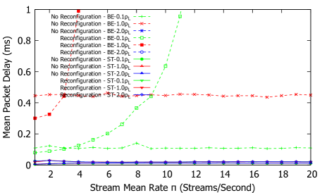
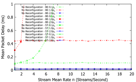
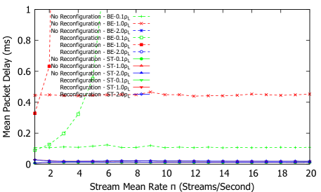
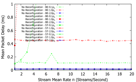
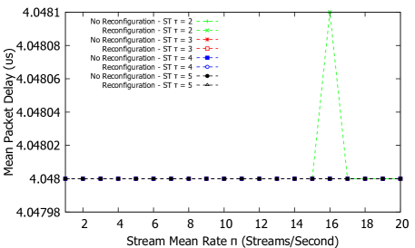
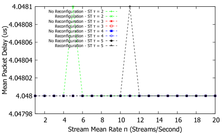
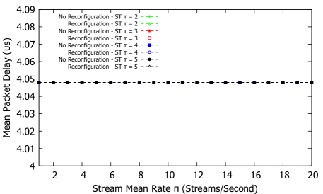
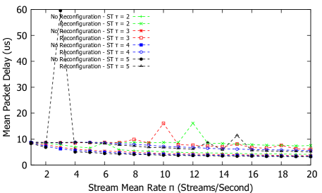
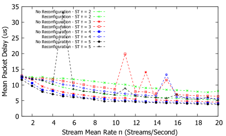
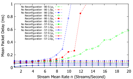
Figs. 6–9 show the average mean delay for ST traffic and for BE traffic for the centralized unidirectional ring topologies. The average delays in general are low and stable for both BE and ST traffic. Since the CNC manages the ST traffic streams and therefore guarantees the bandwidth rates needed to transmit across a single switch hop in one CT, the ST delays are less than s for all values. The ST delays with reconfiguration active at the CNC experience higher delays than “No Reconfiguration” since we essentially push more frames into the network that increase the queuing delay. BE traffic experiences much higher delays than ST. With the “No Reconfiguration” approach, the BE traffic delay is near constant since the gating ratio is left unchanged throughout the simulation. For the test with reconfiguration, the BE mean delay increases dramatically since we tend to accept and exhaust the CT with ST streams over the course of the simulation run.
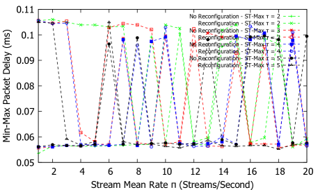
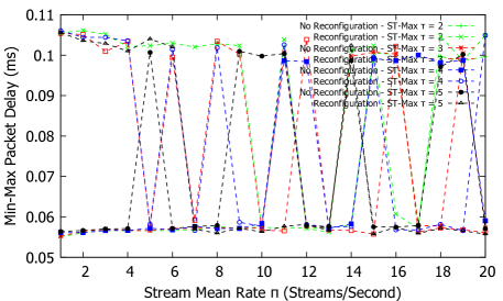
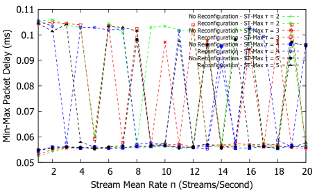
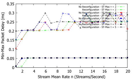
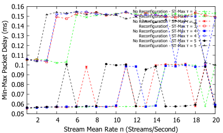
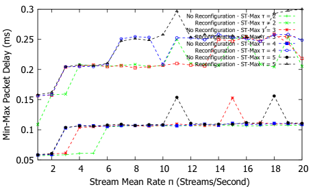
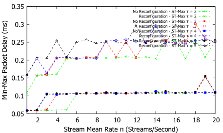
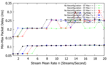
As mentioned in the introduction section, TSN needs to guarantee and bound the maximum delay in order to deterministically forward traffic across a TSN domain. Fig. 10 shows the maximum delay evaluation for ST traffic. For the unidirectional ring topology with a maximum of five hop streams, the reconfiguration approach maximum delay is bounded at ms, while for the “No reconfiguration” approach, the max delay is bounded at nearly s. For TAS and the CNC’s registration and reservation procedure, the guarantee is applied to bandwidth as a share of the egress port using time division multiplexing. With the parameters chosen empirically, the maximum delays is capped to approximately s which is ideal for the topology chosen and critical ST traffic.
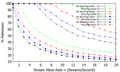


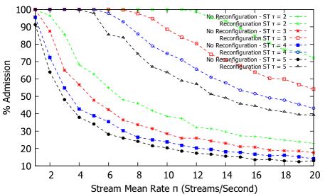
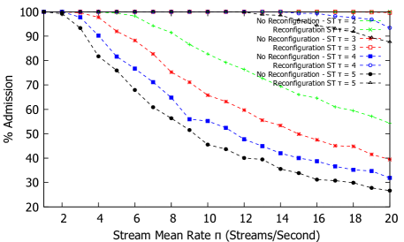
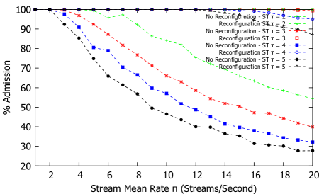
While QoS metrics are important, another factor that determines the performance gains is the admission ratio for the system. Fig. 11 shows the stream admission ratio that results for both reconfiguration and no reconfiguration. In general, each generated stream needs a data rate of about Mbps for a 50 s CT for each egress port on the stream’s path with one ST packet rate per CT and fixed packet size of B. With an egress port channel capacity of , approximately streams can be guaranteed. Compared to the “no reconfiguration” approach, the reconfiguration significantly improves the admission rates at the cost of higher BE traffic delays since the ST slot borrows BE time slots to accommodate the ST streams.
CDT traffic that requests transmission guarantees from the CNC experiences some delay before being either admitted or rejected. Fig. 12 shows the average signaling latency for ST stream registration. Since the control plane is out-of band from the data plane within the TSN domain, the delay is constant throughout the simulation run.

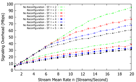
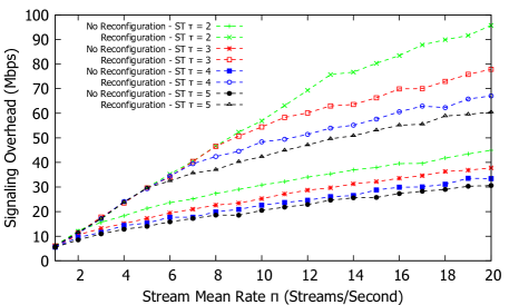
Stream registration and reservation introduces some control plane overhead. Fig. 13 shows the signaling performance overhead. More specifically, the overhead is measured at the CNC or both incoming and outgoing control (CDT) traffic. Generally, the reconfiguration approach introduces more signaling overhead; however, Ethernet generally has large bandwidths, thus the CDT traffic rates are minimal compared to the link capacities. Furthermore, when , we observe higher signaling overhead due to accepting larger numbers of streams (rejections are inexpensive compared to acceptance) both with and without reconfiguration.
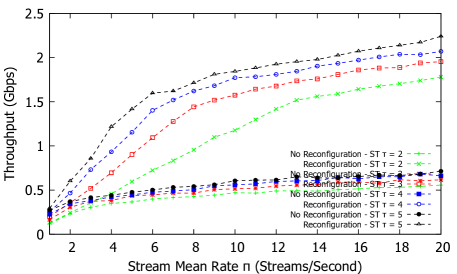


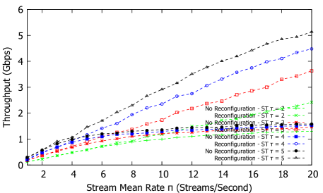
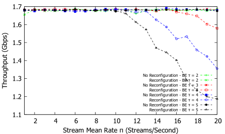
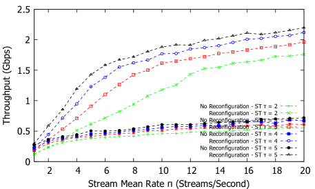
Observing the network’s throughput gain, Fig. 14 and Fig. 15 show the average throughput measured at the sink for both ST and BE traffic. While the total throughput that can be achieved is around Gbps, the maximum throughput allowed is around Gbps since some switches get bottlenecked faster than other switches which restricts the addition of more flows. For the “no reconfiguration” approach, BE traffic is varied between traffic intensity to . Fig. 15[a]–[b] shows an average throughput of Gbps and Gbps, respectively, which is expected and no frames are dropped. However, as the load reaches Gbps and more ST streams are accepted, i.e., the BE traffic time slot is shortened, BE traffic starts to suffer and caps at around Gbps, as shown in Fig. 15[c]. With reconfiguration, BE tends to suffer more since we shift the time slot of BE to ST (maximum of ) and the throughput drops to Gbps as shown in Fig. 15[b][c].


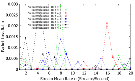
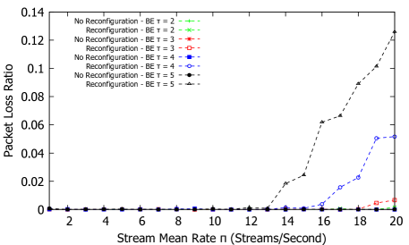
To show the performance of the CNC management of streams, Fig. 16 and Fig. 17 show the packet loss ratio for ST and BE traffic in the network. Since the CNC manages only ST streams, the TSN guarantees (which include zero packet loss since retransmissions are in general too expansive for ST traffic) are only valid for ST streams. For BE under the reconfiguration approach, as the load for ST traffic increases, the packet loss increases as well. For the “no reconfiguration” approach, the loss typically is constant even for high loads of BE traffic.
Overall, the reconfiguration approach certainly provides a means to manage and to ensure that the number of ST streams is maximized according to the link capacity. However, we observe from the results and the topology used that any bottleneck switch can generally reduce the link utilization which can significantly drop the throughput, even if the delay and loss are guaranteed. Selecting different paths (if one exists) and modeling the queue to ensure maximum ST stream delays can help potential bottleneck links and increase throughput throughout the network.
V-B2 Bi-Directional Ring Topology


The unidirectional ring topology certainly simplifies the complexities of calculating the ST slot window. However, to show the a more pronounced gain in stream utilization and admission, a bi-directional ring topology is used with static shortest path routes. The two port switch now has two paths to the destination according to the hop count specified in Table. II, where about of streams take one port and the rest () take the other port. Note that the edge links (switch to sink and source to switch) are given higher link capacities to avoid congestion at the edges where the CNC currently does not control (at least Gbps for the bi-directional ring). Fig. 18 - 21 shows the average mean delay evaluation for both ST and BE traffic under different stream lifetime values, . Compared to the unidirectional topology, the bi-directional provides significantly better delay results since an extra port with full-duplex link support now provides extra capacity to service streams giving more slot reservations to BE even at high ST stream load.
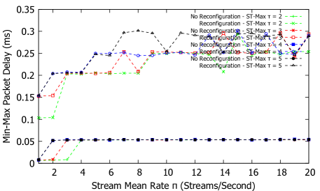
In terms of maximum delays, the bi-directional topology configuration produces higher than expected max delays due to the increasing ST stream acceptance without taking into account queue delays. For the bi-directional topology tests, the queue sizes were left the same (see Table. I) and the CNC typically guarantees an upper bound delay per cycle per hop, i.e., each switch hop constitutes a max delay of one CT (or s in our tests). Fig. 22 shows the maximum delay evaluation for ST traffic for the bi-directional ring topology with CNC present. With the “no reconfiguration” approach, and since the ST slot size is kept at the initialized value ( of CT or s), the maximum delay is constant at s. However, if reconfiguration is active at the CNC, then the maximum delay is bounded at s due to the high admission rate and larger queuing delay per cycle. Note that the maximum hop traversal for any ST stream is kept at hops due to the bi-directional topology.
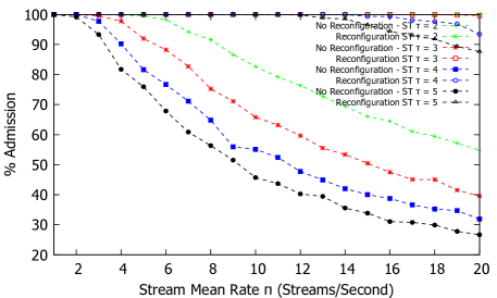
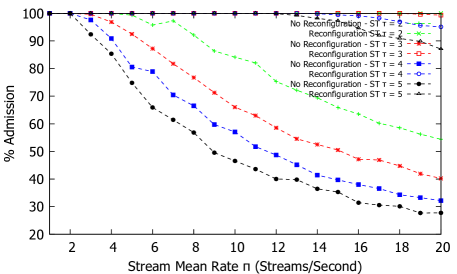
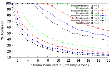
While the max delay suffers due to not taking into account queuing delay in general, the admission rate is much higher (by about ) at high ST loads. Fig. 23 shows the stream admission ratio results. With and , the admission rate is close to for the bi-directional topology with reconfiguration active at the CNC. In contrast, the “no reconfiguration” approach improves slightly (by about ) compared to the unidirectional ring since the initialized gating ratio is too restrictive and can largely underutilize the link. Note that while we show the admission rates for different BE loads, , the admission ratio does not change since TAS effectively segments the traffic at the egress switch/port, i.e., BE traffic does not block at ST traffic.

Similar to the unidirectional ring, the bidirectional ring topology provides constant signaling delay due to the CNC out-of band signaling channels. Fig. 24 shows the signaling delay for ST stream registration. Note that the average signaling delay is lower than in the unidirectional ring since the edge links, specifically the source to switch link, is larger than in the unidirectional ring hence the transmission delay is shorter.
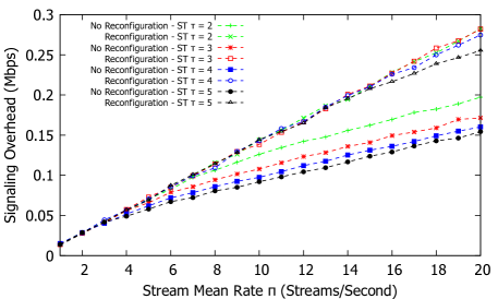
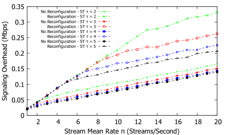
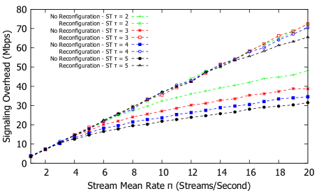
Since the topology is effectively the same (albeit having another port to the switch), the signaling overhead in general is very similar to the unidirectional topology. Fig. 25 shows the signaling performance overhead. Note that while the hop traversal is reduced (since the stream can take one of two paths to the destination governed by hop traversal), the number of sent and received CDT frames are the same in general. Clearly, similar to the unidirectional topology, the reconfiguration approach generates more CDT traffic. Note that rejections in general are less costly in terms of sent and received frames in the network. Therefore, the higher the admission rate, the more overhead is observed in the control plane, though based on Fig. 25, the overall overhead is not even close to Mbps and therefore is much lower compared to the channel capacity.


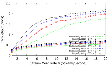
In terms of overall throughput, Fig. 26 and Fig. 27 shows the average throughput measured at the sink for both ST and BE traffic for the bi-directional ring topology. Compared to the unidirectional ring, the throughput for the bi-directional ring is much higher (sink maximum capacity is around Gbps from all switch to sink channels).


Similar to the unidirectional ring topology, bi-directional topology achieves zero loss to ST streams while significantly improving the loss rate for BE traffic. Fig. 28 and Fig. 29 shows the packet loss ratio for ST and BE traffic in the network for the bi-directional ring topology. Maximum BE loss as high BE traffic intensity, , is around which is a significant reduction from the unidirectional topology (of around ).
In contrast to the unidirectional topology, the bi-directional topology with reconfiguration active at the CNC achieves improved QoS metrics and admission rates. However, without modeling the queue characteristics and guaranteeing queuing delay, it is difficult to guarantee maximum delays. Modeling the ST queue at each egress port in conjunction with TAS configuration properties grants the possibility to produce deterministic forwarding plane at the data plane for ST streams. This part is left for the next iteration of this report.
V-C Decentralized Model Evaluation
In evaluating the proposed solution describes in more detail in section IV, we consider both periodic and sporadic sources for ST and BE traffic as discussed in section V-A2 respectively. We evaluated network with TAS shaper on the industrial control loop unidirectional and bi-directional topology and results are collected for tests following the simulation parameters shown in Table.I.
V-C1 Unidirectional Ring Topology

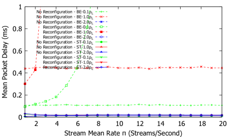

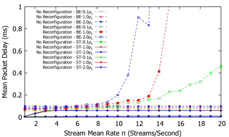
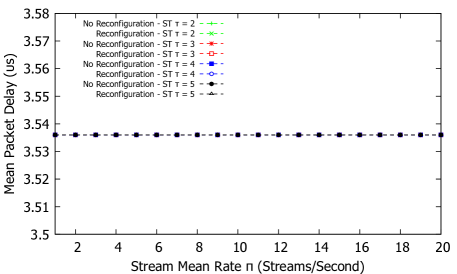
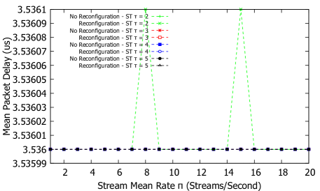
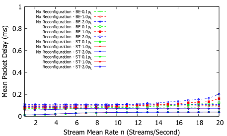
Decentralized model essentially transfers some of the CNC functions (e.g., TAS reconfiguration and resource reservation modules) from the centralized model down to the data plane switch’s egress TAS enabled ports. The main difference between the centralized and decentralized models is the signaling performance which is now in-band and can affect data traffic. Fig. 30 - 33 shows the average mean delay evaluation for both ST and BE traffic. While the CDT traffic is in-band, the average delay is about the same as the centralized topology average delay in Fig. 6 - 9. Typically, the ST stream’s average delay is minimal to near constant for both the reconfiguration and “no reconfiguration” approaches. For BE, the “no reconfiguration” approach produces constant average delay for each BE traffic intensity. When used with reconfiguration, the mean delay start to democratically increase since BE traffic time slots are begin reserved for ST streams.
In terms of maximum delays under the unidirectional topology using the decentralized model, Fig. 34 shows the maximum delay evaluation for ST traffic. In contrast to the average delay, the maximum delay does get affected by in-band CDT traffic. In the decentralized model, the CDT traffic is given the highest priority above both ST and BE traffic. Therefore, the maximum delays can reach about s more than the ST threshold of s.
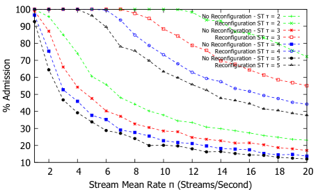
The admission rate is very similar to the centralized model since the network parameters used are identical. Fig. 35 shows the stream admission ratio results.
In contrast to the centralized model, the decentralized model’s in-band CDT traffic implies varied stream signaling delays as shown in Fig. 36 which shows the signaling delay for ST stream registration. As the number of streams generated () increase, the overall average signaling delay decreases which is due to the increased rejections as more streams attempt to request network resources. In the decentralized model, a rejection by an intermediate bottlenecked switch implies a termination of the CDT traffic and a notification to any previous pending stream records to cancel the potential reservation and eventually notify the source of the rejection. If this rejection happens closer to the source in the CDT registration procedure, then the average delay will be much shorter when compared to an stream acceptance. In general, the average stream signaling delay is in the order of microseconds which is reasonable for most industrial control systems applications.
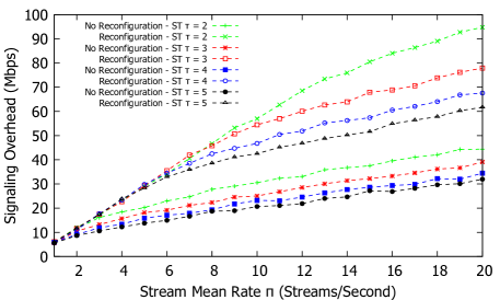
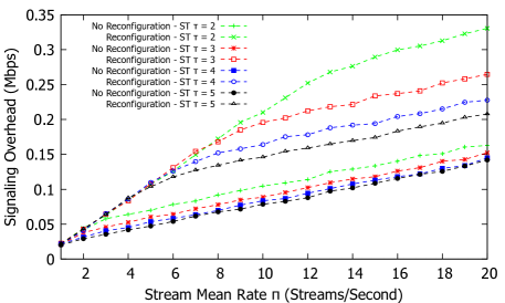
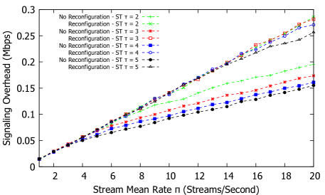
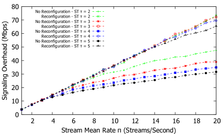
Generally, the decentralized model produced greater signaling overhead than the centralized model since CDT traffic is measured at each data traffic port for incoming and outgoing as shown in Fig. 37. Analogous to the signaling delay, the more ST streams accepted, the more overhead is observed. Therefore, as increases and consequently, the more rejections occur, the lower the overhead. As shown in Fig. 37, the results for the signaling overhead with reconfiguration shows a more pronounced difference with varied values.

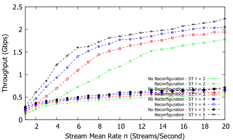
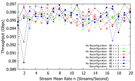
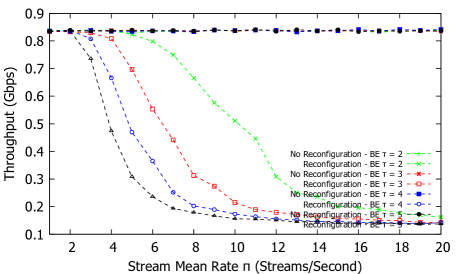
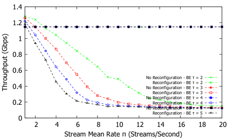
Throughput results are generally the same when compared to the unidirectional centralized model. Fig. 38 and Fig. 39 shows the average throughput measured at the sink for both ST and BE traffic.


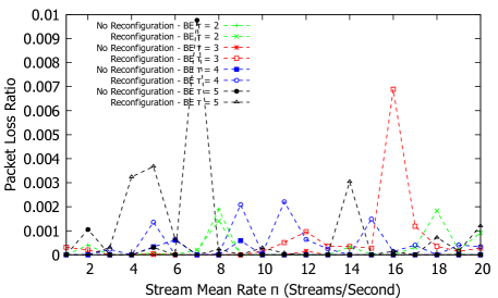
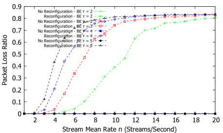
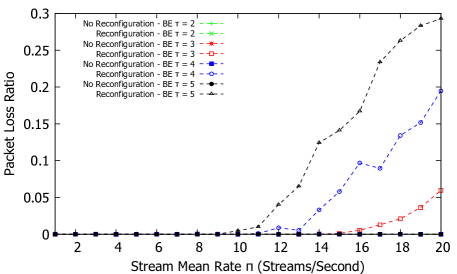
Similarly, the packet loss rate is nearly similar to the unidirectional centralized model as shown in Fig. 40 and Fig. 41 for ST and BE traffic in the network respectively. The unidirectional topology with either the centralized or decentralized approach generally get bottlenecked much faster compared to the bi-directional results. Therefore, BE traffic quickly suffers as more ST streams request TAS slot reservation. In terms of added improvements, changing the cycle time (GCL time) to different values depending on both ST and BE traffic proportions can generally improve BE traffic whilst still guaranteeing ST streams. In typical industrial environments, ST streams have generally low data rates, are less frequent, and smaller in size than BE traffic, and therefore can be admitted quite easily without much effect on BE traffic.
V-C2 Bi-Directional Ring Topology

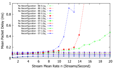
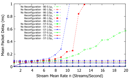
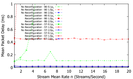
In the bi-directional topology using the decentralized model, in-band CDT traffic affects the data traffic similar to the unidirectional model. Fig. 42 - 45 shows the average mean delay evaluation for both ST and BE traffic. As is increased, i.e., the number of streams at any time increase, the BE slot reservations are reserved for ST streams which affects BE QoS mean delay.
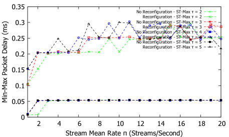
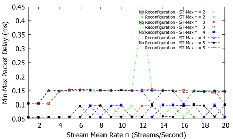
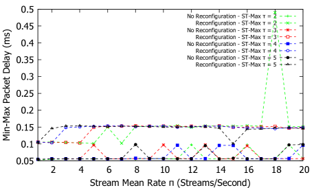
In terms of maximum delay, Fig. 46 shows the maximum delay evaluation for ST traffic. While the reconfiguration approach looks very similar to the centralized model, the “no reconfiguration” approach gets affected by in-band CDT traffic that raises the max delay in some cases to s.
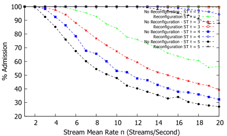
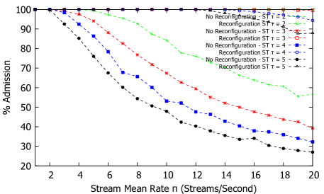
Admission rate is exactly the same as the centralized model as shown in Fig. 47 given the same networking parameters.
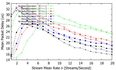
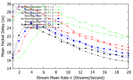
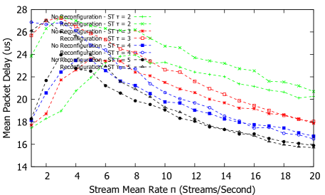
Fig. 48 shows the signaling delay for ST stream registration.It is observed that as the ST stream generation increases, so does the mean signaling delay up to a stream mean rate, . The mean delay starts to decrease as the load keeps increasing.
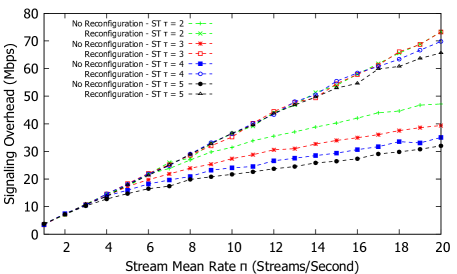
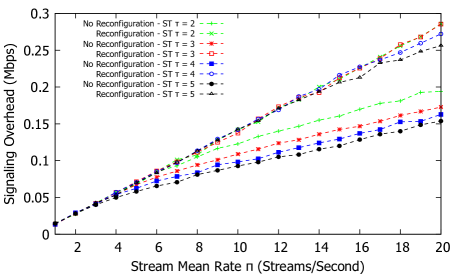
The stream signaling overhead produces results that are the same as the decentralized model as shown Fig. 49. In general, the results between different values are close since for any value, almost all the streams are getting accepted generating the same overhead in total.
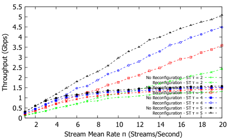
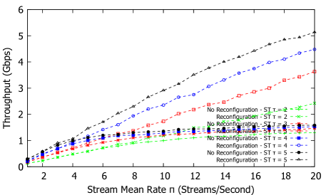
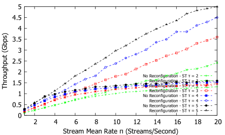
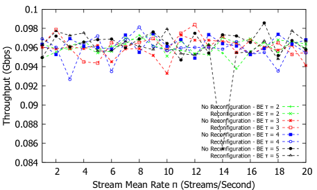
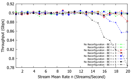

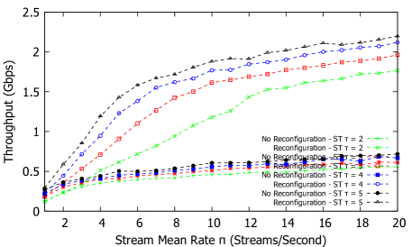
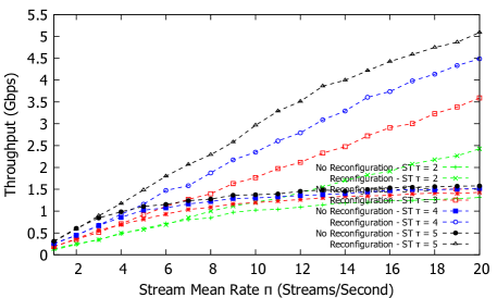
Fig. 50 and Fig. 51 shows the average throughput measured at the sink for both ST and BE traffic. The average throughput results are nearly identical to the centralized model. While it is difficult to see, the throughput is slightly less than the centralized since we now incorporate in-band control traffic while reduces the link utilization for data traffic.

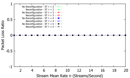

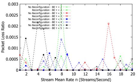
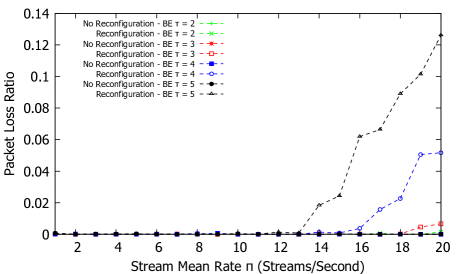

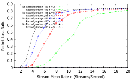
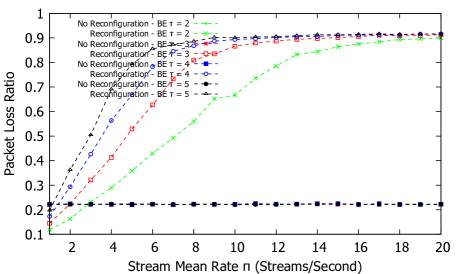
Fig. 52 and Fig. 53 shows the packet loss ratio for ST and BE traffic in the network. Similar to all the different models and topologies, ST streams have zero frame drops as required by TSN. BE traffic results are nearly identical to the centralized model under bi-directional topology. Similarly, the overall performance is largely improved under the bi-directional topology due to the additional port.
While the decentralized model certainly proves to operate nearly identical to the centralized one in terms of QoS metrics and overall admission rate, the main disadvantage is in-band CDT traffic which can lead to delayed ST streams particularly affecting guaranteed maximum delays violations. A work around is to service all the ST streams first, and then service CDT frames before servicing the BE traffic, though this might lead to additional signaling delays depending on the ST load. However, some applications have a more relaxed constraint in guaranteeing maximum delay but require complete segregation of traffic based on the class of service which can be handled using the decentralized model without the overhead complexities of a CNC device. Furthermore, the decentralized model can struggle to find alternate paths without full network visibility, as opposed to the centralized model which can easily reroute streams in the event of failures due to having full network visibility, though this is out of scope for this phase of the project. Moreover, while not tested in our model, adding new devices and removing devices in the decentralized model leads to information flooding across the network that adds complexity and can skew TAS schedules if not handled appropriately. However, in the centralized model, this “plug and play” feature can be easily extended to our TSN domain since the CNC has full control and management of the data plane and can adjust and coordinate any scheduling issues in a timely and controllable manner.
VI Conclusions and Future Work
The IEEE 802.1Qcc framework and the 802.1Qbv traffic shaper enable the implementation of a deterministic forwarding plane that provides strict guarantees to any scheduled traffic service without any flow or congestion control mechanism at the source. Using an automated network configuration is an imperative tool set to provide a unified communication platform based on commercial of the shelf (COTS) full-duplex Ethernet with high bandwidth/low complexity compared to Controller Area Networks (CANs), Local Interconnect Networks (LINs), and specialized field-buses in industrial control system applications (e.g., industrial control, automotive, avionics). Such network designs can form a contract with the source to forward mission critical traffic and to automate the network configuration process using 802.1Qcc for the full lifetime of the stream. Additionally, depending on the forwarding plane port traffic shaper (e.g., TAS), the required schedules can be passed to the switch servers using general user/network information protocols (e.g., TLV, Yang, SNMP).
In this paper, we have investigated the impact of TAS reconfigurations in response on dynamic network conditions. We have demonstrated the effectiveness of TAS with and without the CNC, i.e., for centralized (hybrid) vs. decentralized (fully distributed) models. We have examined network QoS traffic characteristics when maximizing stream admission to the network whilst reserving some BE time slots in the event of high ST transmission requests.
Based on the insights from the present study we outline the following future research directions. First, it would be interesting to judiciously change the GCL time for switches during reconfiguration whilst satisfying QoS requirements. The studied reconfiguration techniques should also be examined in alternate approaches for providing deterministic Qos, e.g., [22, 23] as well as in the context of related QoS oriented routing approaches, e.g. [24, 25].
In the wider context of QoS networking and related applications, deterministic networking should be examined in the context of emerging multiple-access edge computing (MEC) [26, 27, 28, 29], in particular MEC settings for low-latency applications [30, 31, 32]. As an alternative approach to coordinating the reconfigurations, emerging softwarized control paradigms, such as software defined networking can be explored [33, 34, 35, 36, 37]. Regarding the reliability aspects, a potential future research direction is to explore low-latency network coding mechanisms, e.g., [38, 39, 40, 41, 42, 43, 44], to enhance networking protocols targeting reliable low-latency communication.
References
- [1] N. Finn, “Introduction to time-sensitive networking,” IEEE Communications Standards Magazine, vol. 2, no. 2, pp. 22–28, 2018.
- [2] A. Nasrallah, A. S. Thyagaturu, Z. Alharbi, C. Wang, X. Shao, M. Reisslein, and H. ElBakoury, “Ultra-low latency (ULL) networks: The IEEE TSN and IETF DetNet standards and related 5G ULL research,” IEEE Commun. Surv. & Tut., vol. 21, no. 1, pp. 88–145, 2019.
- [3] ——, “Performance comparison of IEEE 802.1 TSN Time Aware Shaper (TAS) and Asynchronous Traffic Shaper (ATS),” IEEE Access, vol. 7, pp. 44 165–44 181, 2019.
- [4] R. Belliardi, J. Dorr, T. Enzinger, F. Essler, J. Farkas, M. Hantel, M. Riegel, M.-P. Stanica, G. Steindl, R. Wamßer, K. Weber, and S. A. Zuponcic, “Use Cases IEC/IEEE 60802, V1.3,” pp. 1–74, Sep. 2018, available from http://www.ieee802.org/1/files/public/docs2018/60802-industrial-use-cases-0918-v13.pdf; Last accessed Feb. 19, 2019.
- [5] “IEEE Standard for Local and metropolitan area networks – Bridges and Bridged Networks - Amendment 25: Enhancements for Scheduled Traffic,” IEEE Std 802.1Qbv-2015 (Amendment to IEEE Std 802.1Q— as amended by IEEE Std 802.1Qca-2015, IEEE Std 802.1Qcd-2015, and IEEE Std 802.1Q—/Cor 1-2015), pp. 1–57, Mar. 2016.
- [6] “IEEE Draft Standard for Local and metropolitan area networks–Media Access Control (MAC) Bridges and Virtual Bridged Local Area Networks Amendment: Stream Reservation Protocol (SRP) Enhancements and Performance Improvements,” IEEE P802.1Qcc/D2.0, October 2017, pp. 1–207, Jan. 2017.
- [7] F. Chen, “Resource Allocation Protocol (RAP) based on LRP for Distributed Configuration of Time-Sensitive Streams,” 2017, http://ieee802.org/1/files/public/docs2017/tsn-chen-RAP-whitepaper-0917-v01.pdf.
- [8] N. Finn, “IEEE Draft Standard for Local and metropolitan area networks–Media Access Control (MAC) Bridges and Virtual Bridged Local Area Networks Amendment: Link-local Registration Protocol,” IEEE P802.1CS/D1.2 December 2017, Dec. 2017.
- [9] “IEEE Standard for Local and Metropolitan Area Networks—Virtual Bridged Local Area Networks Amendment 14: Stream Reservation Protocol (SRP),” IEEE Std 802.1Qat-2010 (Revision of IEEE Std 802.1Q-2005), pp. 1–119, Sep. 2010.
- [10] M. Lander, P. Raagaard, M. G. Pop, and W. Steiner, “Runtime reconfiguration of time-sensitive networking (TSN) schedules for fog computing,” in Proc. IEEE Fog World Congress (FWC), Oct. 2017.
- [11] P. Pop, M. L. Raagaard, M. Gutierrez, and W. Steiner, “Enabling fog computing for industrial automation through time-sensitive networking (tsn),” IEEE Communications Standards Magazine, vol. 2, no. 2, pp. 55–61, 2018.
- [12] T. Häckel, P. Meyer, F. Korf, and T. C. Schmidt, “Software-defined networks supporting time-sensitive in-vehicular communication,” arXiv preprint arXiv:1903.08039, 2019.
- [13] M. Herlich, J. L. Du, F. Schörghofer, and P. Dorfinger, “Proof-of-concept for a software-defined real-time ethernet,” in Proc. IEEE International Conference on Emerging Technologies and Factory Automation (ETFA), 2016, pp. 1–4.
- [14] N. G. Nayak, F. Dürr, and K. Rothermel, “Time-sensitive software-defined network (TSSDN) for real-time applications,” in Proc. ACM Int. Conf. on Real-Time Networks and Systems, 2016, pp. 193–202.
- [15] ——, “Incremental Flow Scheduling & Routing in Time-sensitive Software-defined Networks,” IEEE Transactions on Industrial Informatics, vol. 14, no. 5, pp. 2066–2075, May 2017.
- [16] N. G. Nayak, F. Duerr, and K. Rothermel, “Routing Algorithms for IEEE802. 1Qbv Networks,” in Proc. RTN Workshop, ECRTS, 2017.
- [17] T. Kobzan, S. Schriegel, S. Althoff, A. Boschmann, J. Otto, and J. Jasperneite, “Secure and time-sensitive communication for remote process control and monitoring,” in Proc. IEEE Int. Conf. on Emerging Techn. and Factory Autom. (ETFA), vol. 1, 2018, pp. 1105–1108.
- [18] R. Enns, M. Bjorklund, A. Bierman, and J. Schönwälder, “Network Configuration Protocol (NETCONF),” RFC 6241, Jun. 2011. [Online]. Available: https://rfc-editor.org/rfc/rfc6241.txt
- [19] A. Bierman, M. Bjorklund, and K. Watsen, “RESTCONF Protocol,” RFC 8040, Jan. 2017. [Online]. Available: https://rfc-editor.org/rfc/rfc8040.txt
- [20] J. W. Guck, M. Reisslein, and W. Kellerer, “Function split between delay-constrained routing and resource allocation for centrally managed QoS in industrial networks,” IEEE Transactions on Industrial Informatics, vol. 12, no. 6, pp. 2050–2061, 2016.
- [21] A. Varga and R. Hornig, “An overview of the OMNeT++ simulation environment,” in Proc. ICST International Conference on Simulation Tools and Techniques for Communications, Networks and Systems & Workshops, 2008, pp. 1–10.
- [22] A. Nasrallah, V. Balasubramanian, A. Thyagaturu, M. Reisslein, and H. ElBakoury, “TSN algorithms for large scale networks: A survey and conceptual comparison,” arXiv preprint arXiv:1905.08478, 2019.
- [23] M. Seaman, “Paternoster policing and scheduling, Revision 2.1,” May 2019, available from http://www.ieee802.org/1/files/public/docs2019/cr-seaman-paternoster-policing-scheduling-0519-v04.pdf, Last accessed May 25, 2019.
- [24] U. Chunduri, A. Clemm, and R. Li, “Preferred Path Routing - a next-generation routing framework beyond Segment Routing,” in Proc. IEEE Global Commun. Conf. (GLOBECOM), Dec 2018, pp. 1–7.
- [25] J. W. Guck, A. Van Bemten, M. Reisslein, and W. Kellerer, “Unicast QoS routing algorithms for SDN: A comprehensive survey and performance evaluation,” IEEE Communications Surveys & Tutorials, vol. 20, no. 1, pp. 388–415, First Qu. 2018.
- [26] T. Doan-Van, A. Kropp, G. T. Nguyen, H. Salah, and F. H. Fitzek, “Programmable first: Automated orchestration between MEC and NFV platforms,” in Proc. IEEE Consumer Commun. & Netw. Conf. (CCNC), 2019, pp. 1–2.
- [27] Y. Gao, W. Tang, M. Wu, P. Yang, and L. Dan, “Dynamic social-aware computation offloading for low-latency communications in iot,” IEEE Internet of Things Journal, in print, 2019.
- [28] J. Martín-Pérez, L. Cominardi, C. J. Bernardos, A. De la Oliva, and A. Azcorra, “Modeling mobile edge computing deployments for low latency multimedia services,” IEEE Transactions on Broadcasting, in print, 2019.
- [29] P. Shantharama, A. S. Thyagaturu, N. Karakoc, L. Ferrari, M. Reisslein, and A. Scaglione, “LayBack: SDN management of multi-access edge computing (MEC) for network access services and radio resource sharing,” IEEE Access, vol. 6, pp. 57 545–57 561, 2018.
- [30] M. S. Elbamby, C. Perfecto, M. Bennis, and K. Doppler, “Toward low-latency and ultra-reliable virtual reality,” IEEE Network, vol. 32, no. 2, pp. 78–84, 2018.
- [31] Z. Xiang, F. Gabriel, E. Urbano, G. T. Nguyen, M. Reisslein, and F. H. Fitzek, “Reducing latency in virtual machines: Enabling tactile internet for human-machine co-working,” IEEE Journal on Selected Areas in Communications, vol. 37, no. 5, pp. 1098–1116, 2019.
- [32] K. Zhang, S. Leng, Y. He, S. Maharjan, and Y. Zhang, “Mobile edge computing and networking for green and low-latency Internet of Things,” IEEE Communications Magazine, vol. 56, no. 5, pp. 39–45, 2018.
- [33] R. Amin, M. Reisslein, and N. Shah, “Hybrid SDN networks: A survey of existing approaches,” IEEE Communications Surveys & Tutorials, vol. 20, no. 4, pp. 3259–3306, 2018.
- [34] N. Deric, A. Varasteh, A. Basta, A. Blenk, R. Pries, M. Jarschel, and W. Kellerer, “Coupling VNF orchestration and SDN virtual network reconfiguration,” in Proc. Int. Conf. on Networked Systems (NetSys), 2019.
- [35] A. Destounis, S. Paris, L. Maggi, G. S. Paschos, and J. Leguay, “Minimum cost SDN routing with reconfiguration frequency constraints,” IEEE/ACM Transactions on Networking, vol. 26, no. 4, pp. 1577–1590, 2018.
- [36] W. Kellerer, P. Kalmbach, A. Blenk, A. Basta, M. Reisslein, and S. Schmid, “Adaptable and data-driven softwarized networks: Review, opportunities, and challenges,” Proceedings of the IEEE, vol. 107, no. 4, pp. 711–731, April 2019.
- [37] H. Sándor, B. Genge, and Z. Szántó, “Infrastructure and framework for response and reconfiguration in Industry 4.0,” in Proc. IEEE Int. Symp. on Digital Forensic and Security (ISDFS), 2018, pp. 1–6.
- [38] J. Acevedo, R. Scheffel, S. Wunderlich, M. Hasler, S. Pandi, J. Cabrera, F. Fitzek, G. Fettweis, and M. Reisslein, “Hardware acceleration for RLNC: A case study based on the xtensa processor with the tensilica instruction-set extension,” Electronics, vol. 7, no. 9, p. 180, 2018.
- [39] A. Cohen, D. Malak, V. B. Bracha, and M. Medard, “Adaptive causal network coding with feedback for delay and throughput guarantees,” arXiv preprint arXiv:1905.02870, 2019.
- [40] A. Engelmann, W. Bziuk, A. Jukan, and M. Médard, “Exploiting parallelism with random linear network coding in high-speed Ethernet systems,” IEEE/ACM Transactions on Networking (TON), vol. 26, no. 6, pp. 2829–2842, 2018.
- [41] F. Gabriel, S. Wunderlich, S. Pandi, F. H. Fitzek, and M. Reisslein, “Caterpillar RLNC with feedback (CRLNC-FB): Reducing delay in selective repeat ARQ through coding,” IEEE Access, vol. 6, pp. 44 787–44 802, 2018.
- [42] D. E. Lucani, M. V. Pedersen, D. Ruano, C. W. Sørensen, F. H. Fitzek, J. Heide, O. Geil, V. Nguyen, and M. Reisslein, “Fulcrum: Flexible network coding for heterogeneous devices,” IEEE Access, vol. 6, pp. 77 890–77 910, 2018.
- [43] Z. Ma, M. Xiao, Y. Xiao, Z. Pang, H. V. Poor, and B. Vucetic, “High-reliability and low-latency wireless communication for internet of things: Challenges, fundamentals and enabling technologies,” IEEE Internet of Things Journal, in print, 2019.
- [44] S. Wunderlich, F. Gabriel, S. Pandi, F. H. Fitzek, and M. Reisslein, “Caterpillar RLNC (CRLNC): A practical finite sliding window RLNC approach,” IEEE Access, vol. 5, pp. 20 183–20 197, 2017.