∎
22email: freda,gianni,pirri@diag.uniroma1.it 33institutetext: A. Gawel, R. Dubé, R. Siegwart and C. Cadena 44institutetext: Autonomous Systems Lab - ETH Zurich, Switzerland
44email: gawela, rdube, rsiegwart, cesarc@ethz.ch
3D Multi-Robot Patrolling with a Two-Level Coordination Strategy
Abstract
Teams of UGVs patrolling harsh and complex 3D environments can experience interference and spatial conflicts with one another. Neglecting the occurrence of these events crucially hinders both soundness and reliability of a patrolling process. This work presents a distributed multi-robot patrolling technique, which uses a two-level coordination strategy to minimize and explicitly manage the occurrence of conflicts and interference. The first level guides the agents to single out exclusive target nodes on a topological map. This target selection relies on a shared idleness representation and a coordination mechanism preventing topological conflicts. The second level hosts coordination strategies based on a metric representation of space and is supported by a 3D SLAM system. Here, each robot path planner negotiates spatial conflicts by applying a multi-robot traversability function. Continuous interactions between these two levels ensure coordination and conflicts resolution. Both simulations and real-world experiments are presented to validate the performances of the proposed patrolling strategy in 3D environments. Results show this is a promising solution for managing spatial conflicts and preventing deadlocks.
Keywords:
3D patrolling 3D multi-robot systems distributed multi-robot coordination UGVs1 Introduction
Multi-robot patrolling is a relevant area of investigation in Artificial Intelligence (AI) and robotics since the early nineties (see portugal2011 for a survey and Portugal-2013a for a study on strategies and algorithms). Still, the literature is limited to abstract agents and robots that hardly can be operated in full 3D environments.
Multi-agents and multi-robot patrolling methods have been largely treated in the literature for agents and robots operating in laboratory settings and in allegedly 2D flat environments. However, very little has been done so far when patrolling (i) concerns real 3D world environments such as emergency or inspection scenarios, and (ii) deals with complex robot structures such as Unmanned Ground Vehicles (UGV). In this regard, the differences are substantial: first, the difficulties to be faced are substantially higher; second, in real scenarios, where professional operators (purportedly trained) act with extreme difficulties, the problems and tasks that need to be addressed are driven by specific current needs and not by abstract strategies.
This work addresses the multi-robot patrolling problem for UGVs operating in full 3D environments. We propose a strategy that minimizes and explicitly manages the occurrences of conflict and interference. These unwanted events can generate deadlocks and severely impact a team of robots when patrolling narrow surroundings due to collapsed infrastructures or other wreckages obstructing passages.
Indeed, despite the fact that fully autonomous robots cannot be involved in human rescue so far, they can certainly assist a human team engaged in several difficult tasks. For example, robots are expected to lift the operators from the burden of assessing the state of the environment such as reachability of specific areas, footing of collapsed building, dangerous pipes, infrastructures and objects, and safe areas where the rescuers can possibly pass through in order to reach relevant objectives. There is nowadays a wealth of literature on the tasks and roles a robot team can perform in order to reduce human risks under these circumstances (recent reviews can be found in kleiner2016 ; jung2017 ). An analysis of robots’ potentials in reducing human risks during disaster response and their associated costs are treated in Tardioli-2015 .
Immediate intervention of robot teams to the aftermath of tragic events (see for example murphy2004 ; kruijff2012 ; nagatani2013 ; kruijff2014 ; kruijff2016 for a list of these episodes) requires urgent solutions and assessments in terms of communication, mapping and areas to be covered for information acquisition. In this context, response time is often a key factor. As a matter of fact, the deployment of several robots in the same disaster area can yield critical success by potentially allowing a faster coverage of larger areas. Furthermore, different orders of robot autonomy are required and long-term human-robot collaboration is desired to preside a disaster area over several days (see e.g. kruijff2012 ).
Therefore, a crucial support to the operators is the ability of the UGVs team to collect information by patrolling the hazardous area and reporting to the operators the gathered knowledge.
To this end, solving spatial conflicts between several robots is crucially required in order to attain optimal patrolling in full 3D environments with large amounts of obstacles and obstructed paths.
In this work, we delineate methods for handling strategies to safely govern UGVs behaviors in close proximity. To show our methodology we focus on autonomous multi-robot path planning and frequency-based patrolling, highlighting the role of robot inference in resolving, sometimes compelling, conflicts. We present a distributed multi-robot patrolling technique, which uses a two-level coordination strategy that minimizes and explicitly manages the occurrence of conflict and interference, considering both topological and metric strategies to solve spatial conflicts. The topological strategy deals with the team coordination by allocating nodes to individual UGVs on a patrolling graph. The metric strategy attains coordination by ensuring safe traversal and collision free multi-robot operation.
We show that the proposed framework is capable of operating in full 3D environments, allowing robots to successfully patrol in uneven and unstructured terrain. The patrolling algorithm is integrated with a 3D pose-graph Simultaneous Localization and Mapping (SLAM) system, allowing robots to continuously update and extend their traversable area as well as register their data in a common reference frame using an OctoMap representation. We also present a novel multi-robot traversability analysis that is based on the local shape of the map point-cloud, the spatial arrangement of the team and the robots planned paths.
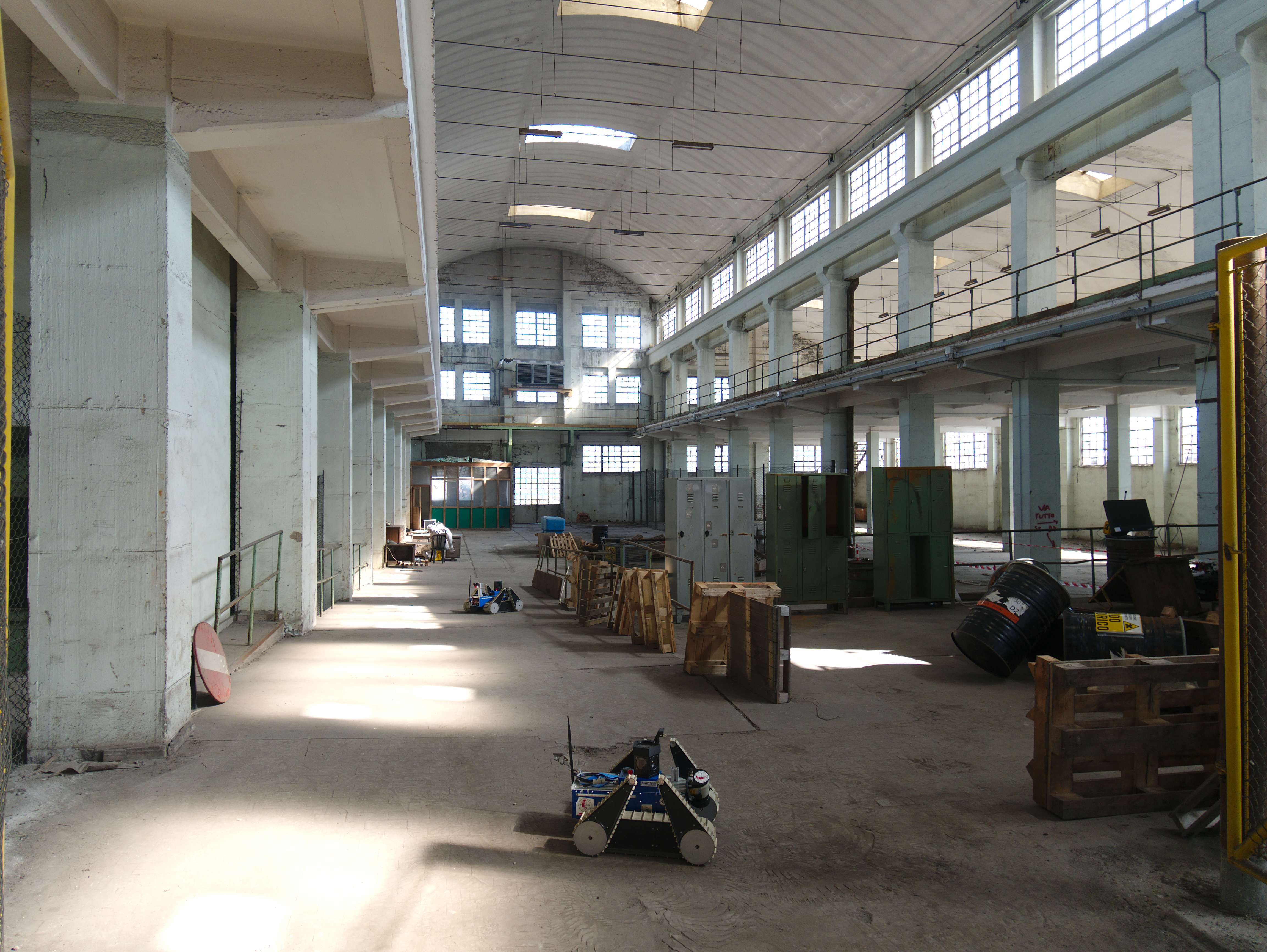
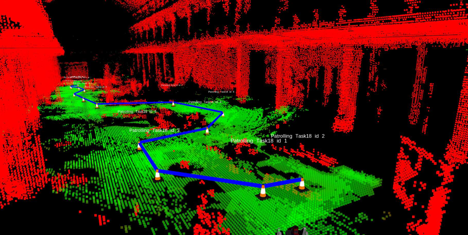
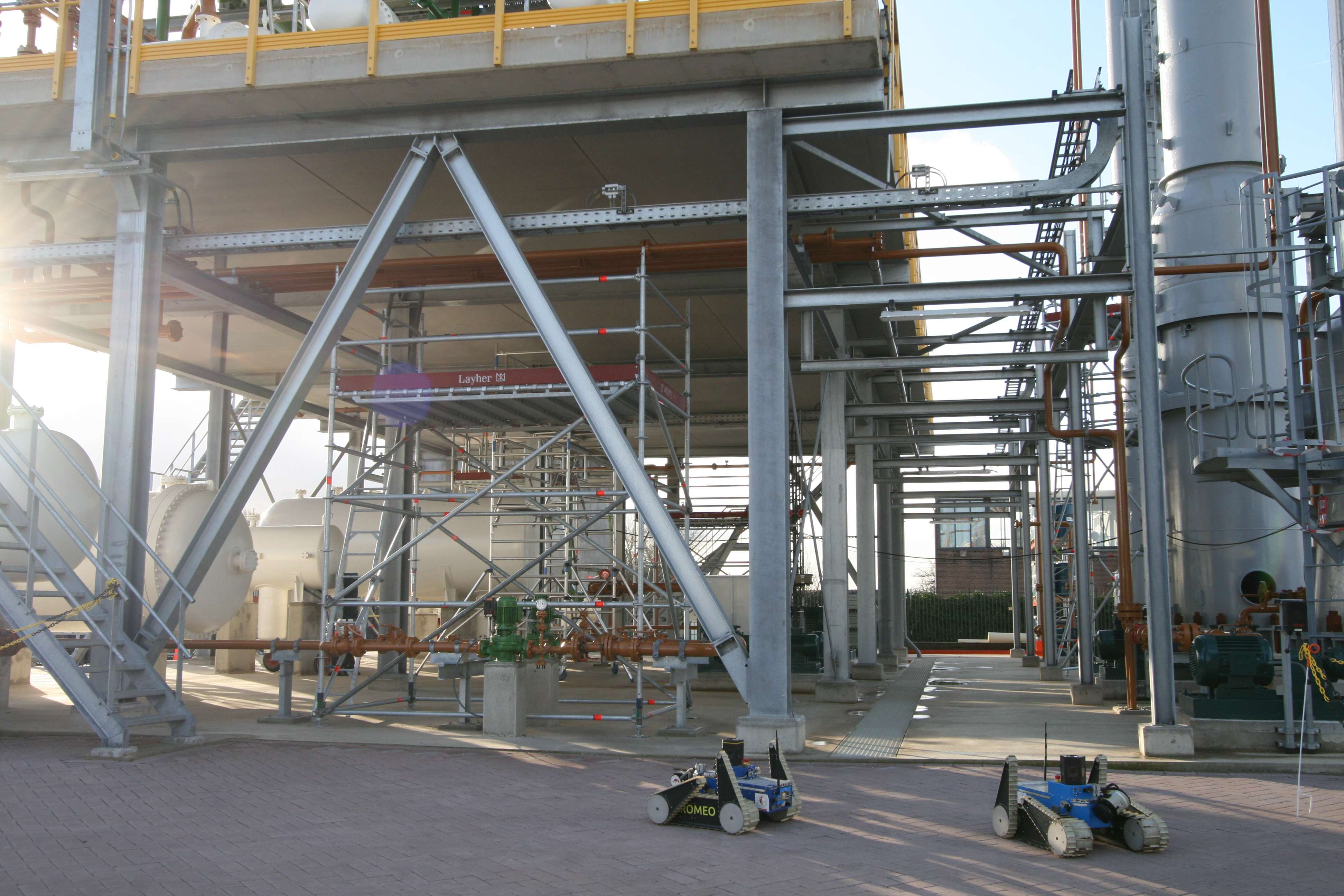
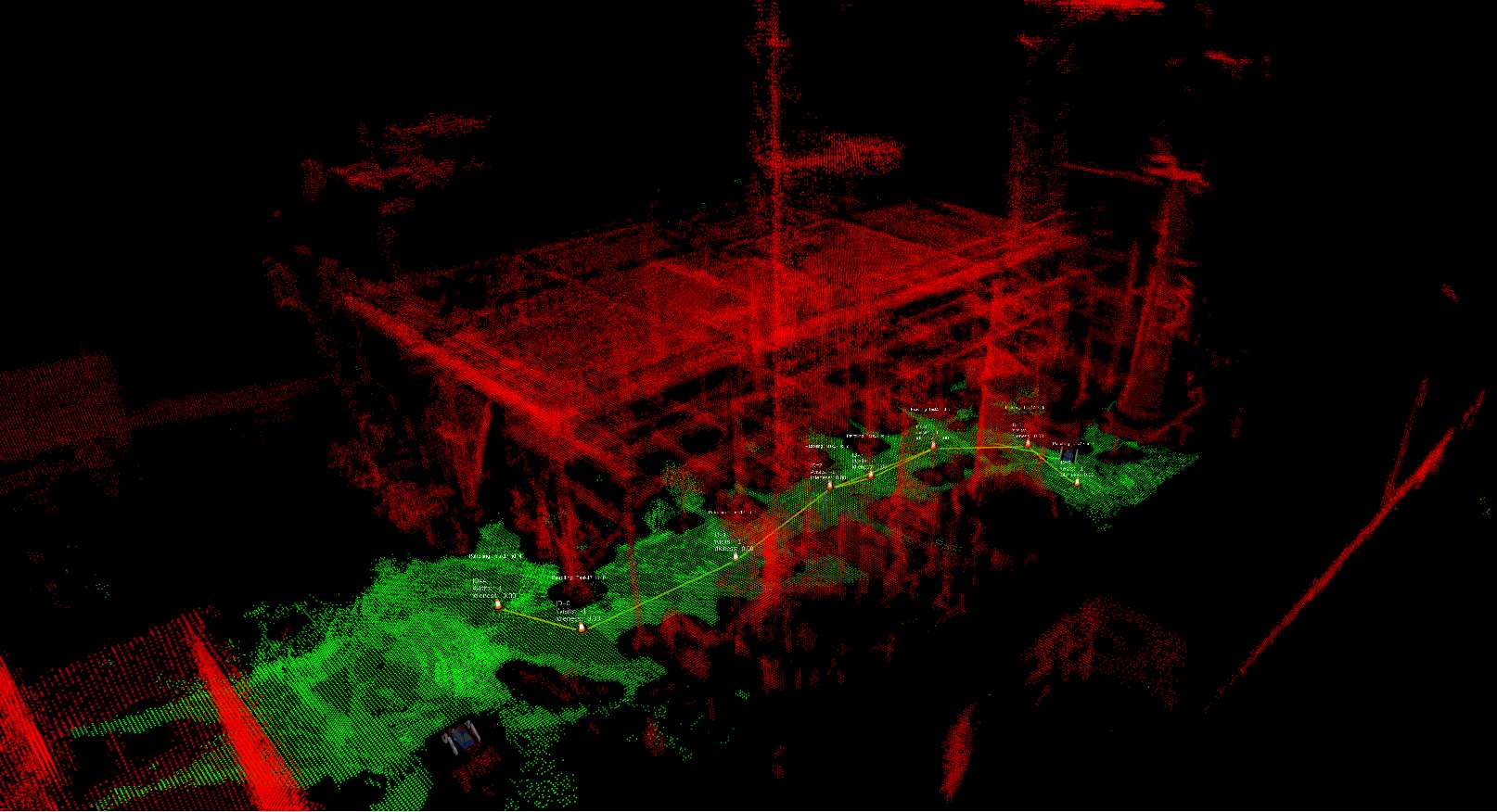
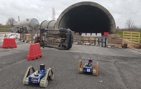
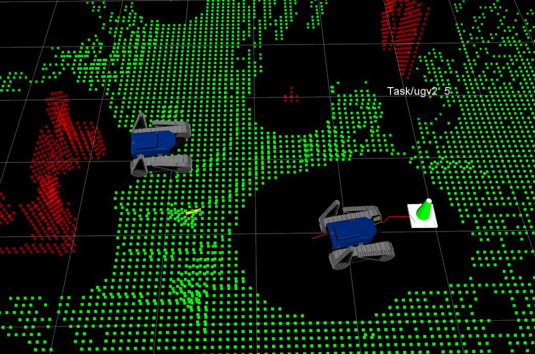
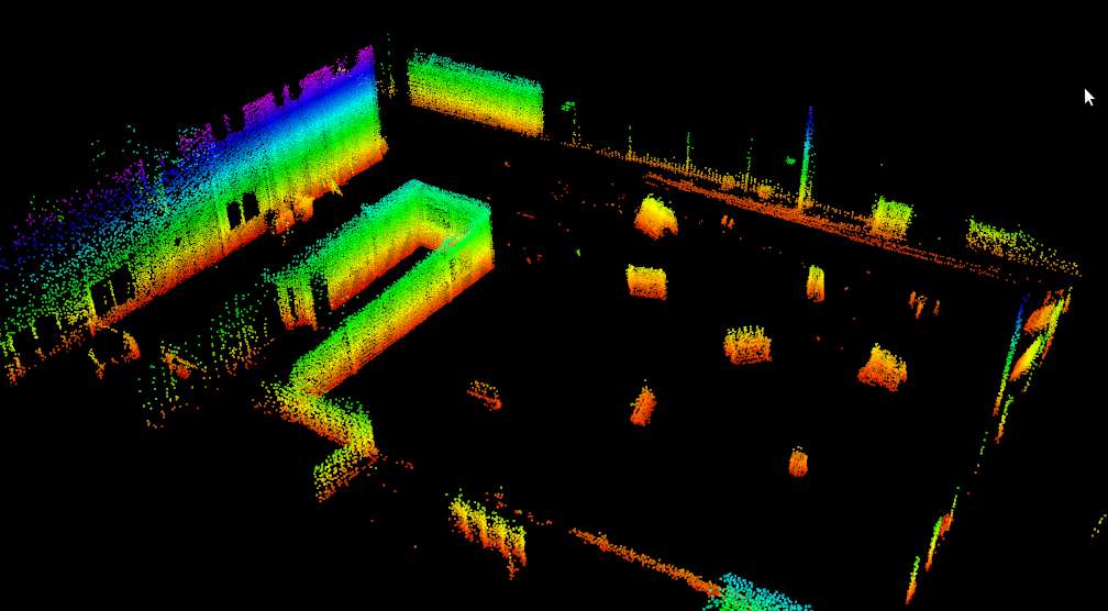
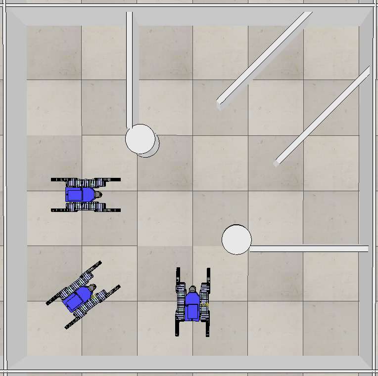
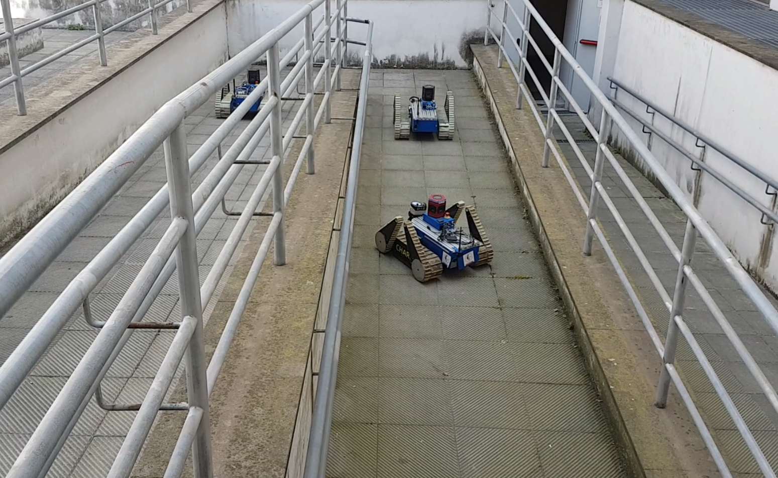
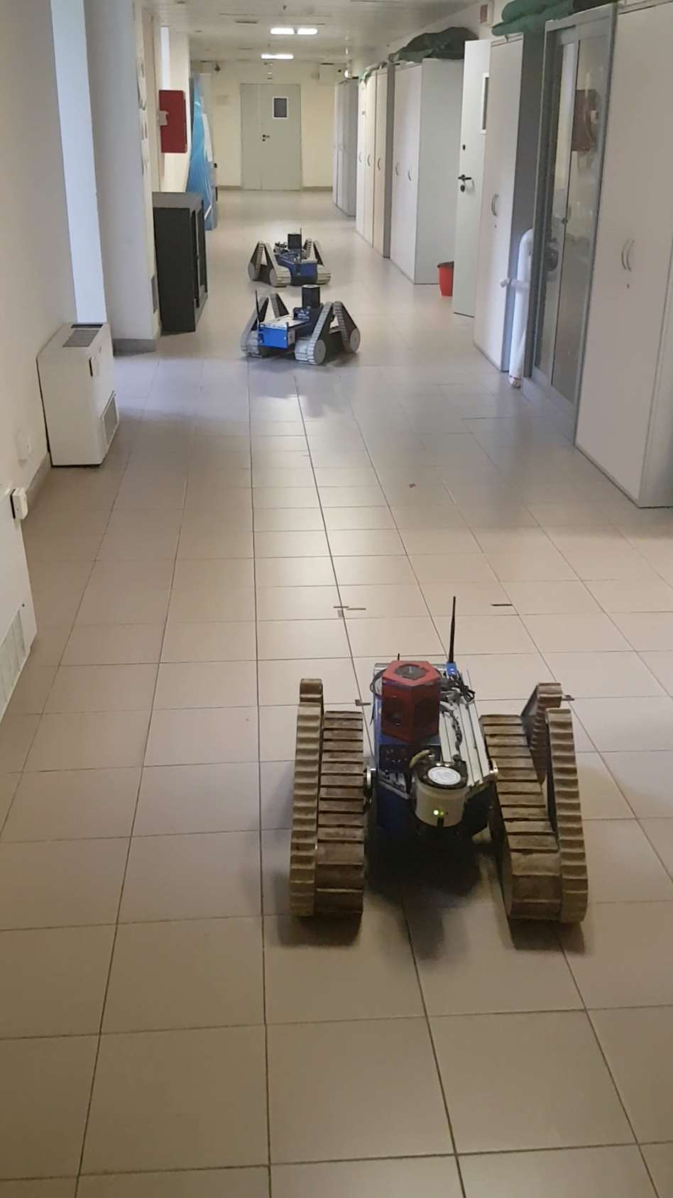
Results shown in Section 10.2 (some examples in real scenarios are depicted in Fig. 1) demonstrate that the proposed system can face and solve an interesting set of spatial conflicts while minimizing interference. Due to the difficulties in operating these UGV systems we augment the set of real world experiments, reported in the experiment section, with simulation experiments that reproduce real scenarios.
In summary, the novel contributions of the work are the following:
-
(i)
Patrolling on a 2D manifold embedded in the 3D space.
-
(ii)
A two level coordination strategy for guiding a team of patrolling robots in a distributed fashion.
-
(iii)
Multi-robot traversability analysis considering teammates planning decisions.
-
(iv)
A validation of our approach in real world environments and in realistic simulation scenarios.
-
(v)
An open source implementation is available111 https://gitlab.com/luigifreda/3dpatrolling.
The proposed strategy is presented within a comprehensive system for 3D multi-robot patrolling.
The remainder of this paper is organized as follows. Section 2 presents an overview of the main challenges that need to be faced by a team of patrolling robots. In Section 3, we survey works on multi-robot patrolling, though none of them faces the real-world conditions we considered in this work. Section 4 describes the problem setup. An overview of the proposed multi-robot patrolling system is given in Section 5.2. In Section 6, we describe the adopted distributed patrolling strategy. Next, Section 7 describes the used multi-robot path planning approach, followed by details on our 3D SLAM system in Section 8. Finally in Section 10.2 we present the results in both real world and simulation experiments and provide implementation details.
2 Problem Overview
A team of UGVs is called to patrol a 3D complex environment. A set of locations of interest is assigned and must be continuously visited in order to monitor their surroundings. The team objective is to maximize the visit frequency of each assigned location. Such a mission poses many challenges.
3D uneven and complex terrain. The UGVs are required to navigate over a 3D uneven and complex terrain. In general, the 3D terrain shape must be efficiently modelled and properly interpreted in order to allow UGVs to robustly localize and plan safe and feasible trajectories. To this aim, a high-level understanding is typically required beyond a basic geometric 3D representation of the scenario.
Spatial conflicts. Narrow passages (for example due to collapsed infrastructures or debris) typically generate spatial conflicts amongst teammates. A suitable strategy is required to (i) minimize interferences and (ii) recognize and resolve possible incoming deadlocks, which can hinder UGVs activities or even provoke major failures.
Dynamic environment. The environment may be dynamic and large-scale Cadena16tro-SLAMfuture . In this case, UGVs must continuously update their internal representations of the surrounding scenario in order to best adapt their behaviours and quickly react to changes. This is a crucial requirement for continuous, efficient and safe operations.
Unreliable communication network. In order to collaborate, UGVs must continuously exchange coordination messages and share their knowledge over a network infrastructure. Indeed, real world networks might be unreliable and offer only a limited communication bandwidth. Therefore, the patrolling strategy must rely on an efficient coordination protocol and show robustness with respect to possible communication failures.
Long-term operations. Patrolling is a long-term task which requires the adoption of suitable persistent models. UGVs are resource-constrained systems which must be able to efficiently select and integrate only relevant information. At the same time, irrelevant sensory data must be filter out and disregarded. These capabilities are crucially required to maintain a compact and usable knowledge representation in the long-term.
We address the aforementioned challenges in the following.
3 Related Work
Multi-robot patrolling has found in recent years several applications in real domains where distributed surveillance, inspection, or control are crucial (e.g., computer network administration Andrade-2001 ; Du-2003 , security Agmon-2014 ; Agmon-2008 ; Hernandez-2014 , Search and Rescue (SaR) Acevedo-2013 ; Aksaray-2015 ; Pippin-2014 , persistent monitoring Song-2014 , hotspot policing Chen-2017 , military Park-2012 ). Typically, in this contexts, a team of robots is required to repeatedly visit a set of areas of interest to be monitored Ahmadi-2006 ; Chevaleyre-2004 ; Elmaliach-2007 ; Machado-2002 ; Portugal-2013a ; Sak-2008 .
Existing approaches can be classified either on the basis of the kind of application Agmon-2014 ; Agmon-2008 or with respect to the applied theoretical principles Chevaleyre-2004 ; Elmaliach-2007 ; Franchi-2009 ; Hernandez-2014 ; Machado-2002 ; Panagou-2016 ; Portugal-2016 ; Santana-2004 . Considering the type of application, existing approaches can be divided in adversarial patrol Yehoshua-2013 , perimeter patrol Agmon-2008a , and area patrol Portugal-2013a . Regarding the theoretical baseline, they can be distinguished in pioneer methods Machado-2002 , graph theory methods Chevaleyre-2004 ; Portugal-2010 , and alternative coordination methods Santana-2004 .
On the basis of recent research advancements in this field, alternative subdivisions might be devised. For instance, alternative coordination methods can be further decomposed in game theory methods Hernandez-2014 , methods resorting to statistical approaches Santana-2004 ; Portugal-2016 , methods using principles from control theory Panagou-2016 , and logic-based methods Aksaray-2015 . An alternative up-to-date review of some of the aforementioned works can be found in Portugal-2016 and in Yan-2016 . The presented work is developed at the intersection of the pioneer methods and the area patrol classes, addressing scalability and computational complexity constraints.
Pioneer methods are commonly based on simple architectures where heterogeneous robots with limited perception and communication capabilities are guided to locations that have not been visited for a while, aiming to maintain a high frequency of visits Portugal-2013a . Under this setting, agents can behave either in a reactive (with local information) or in a cognitive (with access to global information) manner Elmaliach-2007 ; Machado-2002 . Over the years, these methods led to what is today better known as frequency-based patrolling Chevaleyre-2004 ; Elmaliach-2009 . In this type of patrolling, the goal of the team of robots is to optimize a given frequency criterion, usually the idleness Portugal-2010 , that is, the time between consecutive visits to a particular point within the patrol region Pasqualetti-2012 ; Portugal-2013c . In Portugal-2013b , the authors state that in some cases, simple strategies like the pioneer ones, with reactive agents, even without communication capabilities, can achieve equivalent or improved performance when compared to more complex ones. A study of the scalability and performance of some of the patrolling strategies mentioned above has been reported in Portugal-2013a .
Despite the focus that multi-robot patrolling has received recently, it can be noted that there is a lack of practical real-world implementations of such systems Portugal-2013b . When dealing with a team of real robots operating in harsh environments, particular attention has to be payed on the communication, the coordination, and the collaboration amongst teammates for safe joint navigation Acevedo-2016b ; Bereg-2016 ; Shahriari-2016 . Most of the proposed approaches do not account for 3D environments Cabrita-2010 ; Iocchi-2011 ; Pasqualetti-2012 .
In this work, we study the patrolling problem from a non-adversarial point of view. Specifically, we cast the patrolling problem as an online optimization of the point visit frequency (frequency-based patrolling). Even if optimal or near-optimal solutions can be typically guaranteed by off-line methods Chevaleyre-2004 , we select a online framework in order to best face the compelling uncertainty in perceptions, modelling, and action executions. We present a multi-robot system which is able to patrol a 2D manifold of the 3D space.
Many previous multi-robot patrolling systems have been demonstrated under strong assumptions, such as perfect localization, perfect communication or assuming no major failures at path planning level. The drawbacks of these assumptions have been already noticed in the community, “the theoretical strategies need to be adapted to take into account the uncertainties and dynamics of the actual execution” as stated in Farinelli-2016 . In this paper, we present a system tested in real-world scenarios aiming at stepping “towards better validation processes” robin2016multi . Our system approaches the online multi-robot patrolling task by fully considering the 3D space with a SLAM system running on each robot. Specifically, the SLAM system allows the team to be aware of, and adapt to, changes in the environment, for instance, by reassigning goals when a node is no longer reachable for one of the robots due to changes in the traversability map. Furthermore, the presented implementation uses nimbro_network nimbro to handle the communication bandwidth which can be scarce in any full integrated system.
4 The Patrolling Model
| Symbol | Description |
|---|---|
| Environment | |
| Time interval | |
| Surface terrain in | |
| Obstacle region | |
| Configuration space of each robot | |
| Region occupied by robot at | |
| Patrolling graph | |
| 3D metric map of the environment |
In this section we introduce the model and data structures of our patrolling framework. We focus on a team of robots called to patrol an asperous area for which a terrain condition knowledge is required.
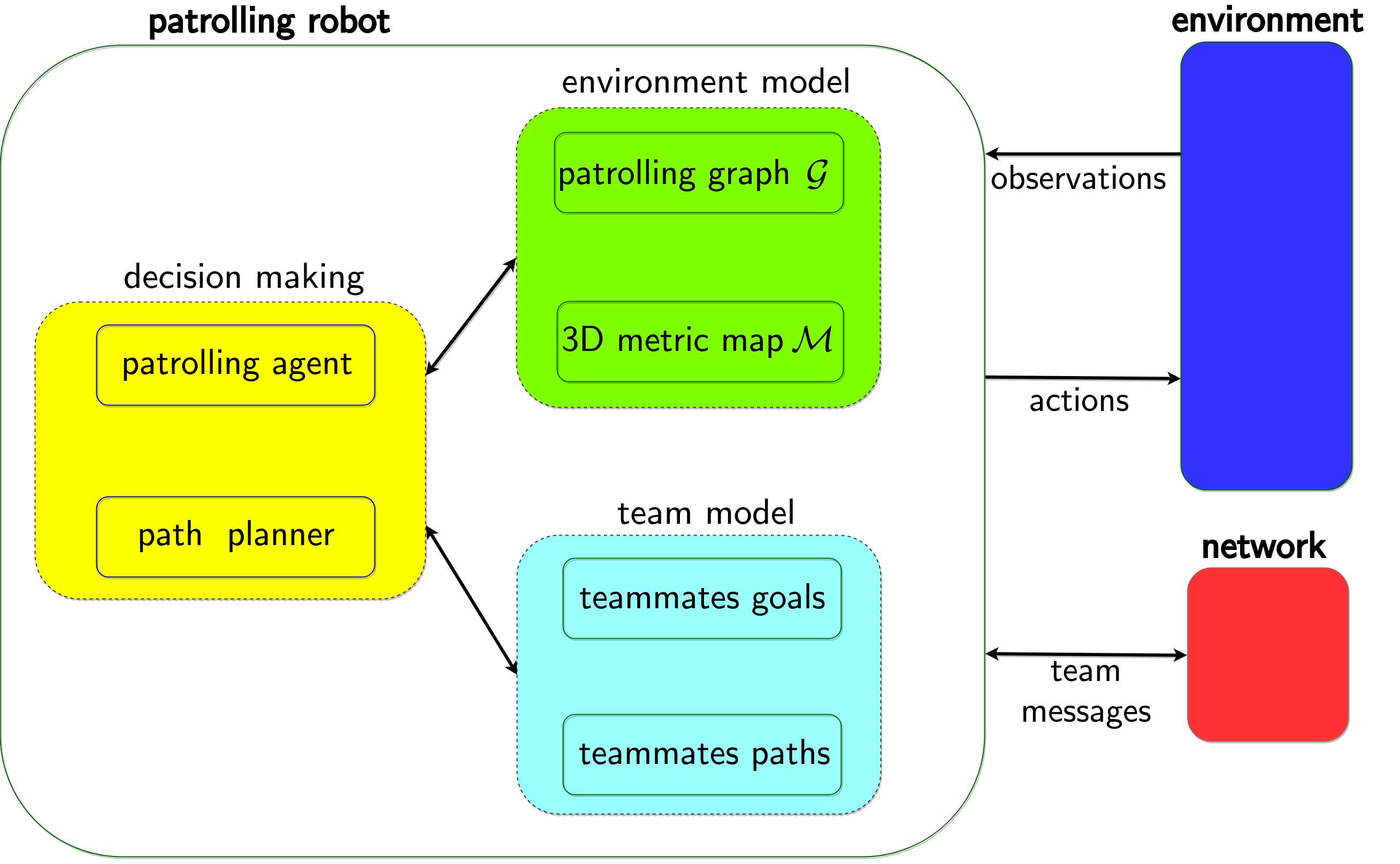
The robot team is composed by ground patrolling robots. The main components of a patrolling robot are represented in Fig. 2. A patrolling robot interacts with its environment through observations and actions, where an observation consists of a set of sensor measurements and an action corresponds to a robot actuator command. Team messages are exchanged with teammates over a network for sharing knowledge and decisions in order to attain team collaboration.
Decision making is achieved by the patrolling agent and the path planner, basing on the available information stored in the environment model and the team model. In particular, the environment model consists of a topological map , aka patrolling graph, and a 3D metric map . The team model represents the robot belief about the current plans of teammates (goals and planned paths).
The main components of the patrolling robots are introduced in the following subsections. A list of the main symbols is reported in Table 1.
4.1 3D Environment, Terrain and Robot Configuration Space
The 3D environment is a compact connected region of . Let denote a time interval, where is the starting time. The obstacle region is in general time-varying and denoted by for every time . We assume is a collection of low-dynamic objects walcott2012dynamic , whose slow motions do not immediately affect results of robot computations.
The robots move on a 3D terrain, which is identified as a compact and connected manifold in .
The configuration space of each robot is the special Euclidean group Lavalle-2006 . In particular, a robot configuration consists of a 3D position of the robot representative centre and a 3D orientation. We denote with the compact region occupied by robot at .
A robot configuration is considered valid if the robot at is safely placed over the 3D terrain . This requires to satisfy some validity constraints defined according to hait2002algorithms .
A robot path is a continuous function . A path is safe for robot in a time interval if for each and each : and is a valid configuration.
We assume each robot in the team is path controllable, i.e., each robot can follow any assigned safe path in with arbitrary accuracy Franchi-2009 .
4.2 Patrolling Graph and Patrolling Agent
A patrolling graph is a topological graph-like representation of the environment to be patrolled.
Namely, is an undirected connected graph, with a set of nodes and a set of edges.
A node is associated to a 3D region of interest , and to a priority weight . In particular, is a ball of pre-fixed radius centred at the corresponding position .
An edge between node and denotes the existence of a safe path connecting the regions and . The length of such a path is used as edge travel cost .
A patrolling graph is built before the mission (see Sect. 9) and assigned to the team at .
A node is visited at time if a robot centre lies inside the associated region at .
The instantaneous idleness of a node at time is , where is the most recent time in the node was visited by a robot. When computing , the priority locally “dilates” or “contracts” time at node . We assume for each node in .
Considering the idleness of a node in a time subinterval , we compute its average idleness , its standard deviation and its maximum value .
The average graph idleness of is
| (1) |
where is the total number of nodes in . is assumed to be constant.
The patrolling plan of a robot is defined as an infinite sequence , where denotes the -th node visited at time by the robot. A team patrolling strategy collects the patrolling plans of all the robots in the team.
Patrolling objective. In our framework, the goal of the robot team is to cooperatively plan a team patrolling strategy that minimizes the average graph idleness at all times .
An instance of the patrolling agent runs on each robot and is responsible of cooperatively generating the patrolling plan according to the above patrolling objective. A pseudo-code description of the patrolling agent is presented in Sect. 6.
| Broadcast message | Description | Affected data in receiving robot |
|---|---|---|
| robot has reached its goal node | node idleness is zeroed in ; the -th tuple in team model is reset | |
| robot is visiting a non-goal node along the way to its goal | node idleness is zeroed in | |
| robot has planned node as perspective goal | the -th tuple in team model is filled with | |
| robot has actually selected node as goal and is heading towards it, is the current path length to the goal | the -th tuple in team model is filled with | |
| robot has planned a path from its current position to its goal, is the corresponding path length | the -th tuple in team model is filled with and the multi-robot traversability map of robot is updated (see Sect. 7.2) | |
| robot aborted its goal node | the -th tuple in team model is reset | |
| robot shares its current idleness estimations | the current idleness estimations are synchronized with according to Algorithm 1 |
4.3 Metric Map and Path-Planning
Each robot of the team is equipped with a rangefinder producing 3D scans222This can be a rotating laser range-finder or a full 3D scanner. and is able to localize in a global map frame, which is shared with its teammates (cfr. Sect. 8).
In our framework, each robot uses a 3D point cloud as a metric representation of the environment. A map is built beforehand and assigned to the team at . A multi-robot traversability cost function is defined on (cfr. Sect. 7.2). This function is used to associate a navigation cost to each safe path (cfr. Sect. 7.4).
Given the current robot position and a goal position , the path planner computes a safe path which minimizes the navigation cost and connects with (cfr. Sect. 7.3). The path planner reports a failure if a safe path connecting with is not found.
4.4 Network Model and Broadcast Messages
Let the network connectivity graph be an undirected graph where a node represents a robot, while an edge represents a communication link between the two connected robot nodes. Specifically, two robots are able to exchange messages if and only if they are connected by an edge in .
We assume is dynamic and stochastic. An edge between any two robots can appear or disappear at any time instant. An independent Bernoulli distribution is associated to each message transmission: any message sent between robots and is successfully received with a probability . We assume the state of is not observable by the robots.
Each robot can broadcast messages in order to share knowledge, decisions and achievements with teammates. In particular, a broadcast message emitted by robot at time is received only by the robots which are connected with robot on at .
Different types of broadcast messages are used by the robots to convey various information (see Sect. 6). In this process, the identification number (ID) of the emitting robot is included in the heading of any broadcast message. In particular, a broadcast message is emitted by a robot in order to inform teammates when it reaches a goal node (reached), visits a node (visited), planned a perspective goal node (planned), selected a node as actual goal and it is heading towards it (selected), and aborts a goal node (aborted). Additionally, a message idlenesses is broadcast in order to enforce the synchronization of idleness estimates amongst teammates (see Sect. 4.5). The path message will be described in Sect. 7.5. Table 2 summarizes the used broadcast messages along with the conveyed information/data. The vector of estimated idlenesses and the team model are introduced in the next two subsections. The general broadcast message format is .
4.5 Shared Knowledge Representation
Each robot of the team stores and updates its individual representation of the world state.
At , a robot loads as input the 3D map and the patrolling graph . Then, it internally maintains an instance of these representations. In particular, we denote by and the local instances of and in robot , respectively.
Since the environment is dynamic, robot updates its individual 3D map by using the last acquired 3D scan measurements (see Sect. 8). This allows the path planner to safely account for new environment changes.
At the same time, robot updates its patrolling graph by using the received broadcast messages and the path planner output. Specifically, the travel cost of an edge in is locally updated when a new path is computed between the two corresponding nodes and .
Additionally, robot locally maintains an idleness estimate for each node in . We denote by the vector of estimated idlenesses in robot . Every time a robot visits(reaches) a node , a visited(reached) message is broadcast and each receiving robot correspondingly updates its local idleness estimate . Clearly, since broadcast messages may be lost, the idleness estimates may not correspond to the actual idleness values. In order to mitigate this problem, each robot continuously broadcasts an idleness message at a fixed frequency . Such messages are used to synchronize the idleness estimates amongst robots according to Algorithm 1.
The above information sharing mechanism implements a shared idleness representation which allows team cooperation, e.g. minimizing inefficient actions such as re-visiting nodes just inspected by teammates.
4.6 Team Model
In order to cooperate with its team and manage conflicts, robot maintains an internal belief representation of the current teammate plans (aka team model) by using a dedicated table
| (2) |
which stores for each robot : its selected goal node , the last computed safe path to , the corresponding travel cost (i.e. the length of ) and the timestamp of the last message used to update .
The table is updated by using reached, planned, selected and aborted messages. In particular, reached and aborted messages received from robot are used to reset the tuple to zero (i.e. no information available). A planned message sets the sub-tuple , with . A selected message sets , while a path message completes the tuple with information.
An expiration time is used to clean of old invalid information. In fact, part of the information stored in may refer to robots which underwent critical failures or whose connections have been down for a while. In particular, let be the current time. A tuple is reset to zero if .
4.7 System Architecture
The patrolling plan of a robot can be pre-computed offline, i.e. before starting the patrolling execution Chevaleyre-2004 ; elmaliach2009multi ; Portugal-2010 , or online, i.e. by planning and visiting a new node at each patrolling step sempe2003adaptive ; Portugal-2013a ; Portugal-Rocha-2013 ; Portugal-2016 .
In a centralized system, the team patrolling strategy is computed by a central control robot (i.e. the leader) and communicated to all its teammates. Conversely, in a decentralized system, a central leader does not exist. Different levels of decentralization are possible and spans from hierarchical to distributed architectures yan2013survey ; farinelli2004multirobot ; baran1964distributed . In a distributed system, each robot independently computes its patrolling plan by possibly taking advantage of exchanged information and coordination messages.
Our system is online and distributed. In particular, an instance of the patrolling agent algorithm (see Sect. 6) runs on each robot and is responsible of online generating its own patrolling plan . Namely, at each patrolling step , the patrolling agent plans a new goal node in . In this process, a patrolling robot exchanges messages with its teammates (see Sect. 4.4) in order to attain coordination (avoid conflicts) and cooperation (avoid inefficient actions). More details are provided in Sect. 5.2.
5 Two Level Coordination Strategy
This section first introduces the notions of topological and metric conflicts, and then presents our two-level coordination strategy (see Sect. 5.2).
5.1 Topological and Metric conflicts
A topological conflict between two robots is defined on the patrolling graph . This occurs when two patrolling agents select the same node as goal (node conflict) or plan to simultaneously traverse the same edge (edge conflict).
On the other hand, metric conflicts are defined in the 3D Euclidean space where two robots are referred to be in interference if their centres are closer than a pre-fixed safety distance . It must hold , where is the bounding radius of each robot, i.e. the radius of its minimal bounding sphere. A metric conflict occurs between two robots if they are in interference or if their planned paths may bring them in interference333That is, the distance between the closest pair of points of the two planned paths is smaller than . .
It is worth noting that topological conflicts may not correspond to metric conflicts. In our framework, an edge may represent a large passage which could be simultaneously traversed by two or more robots without interferences. Similarly, a node may represent a large region which could actually be visited by two or more robots at the same time.
5.2 Two Level Coordination Strategy
Our patrolling strategy is distributed and supported on both topological and metric levels.
The patrolling agent acts on the topological strategy level by selecting the next goal node on . In this process, cooperation is attained by using the shared idleness representation. This avoids inefficient actions such as selecting nodes just inspected by teammates (see Sect. 4.5).
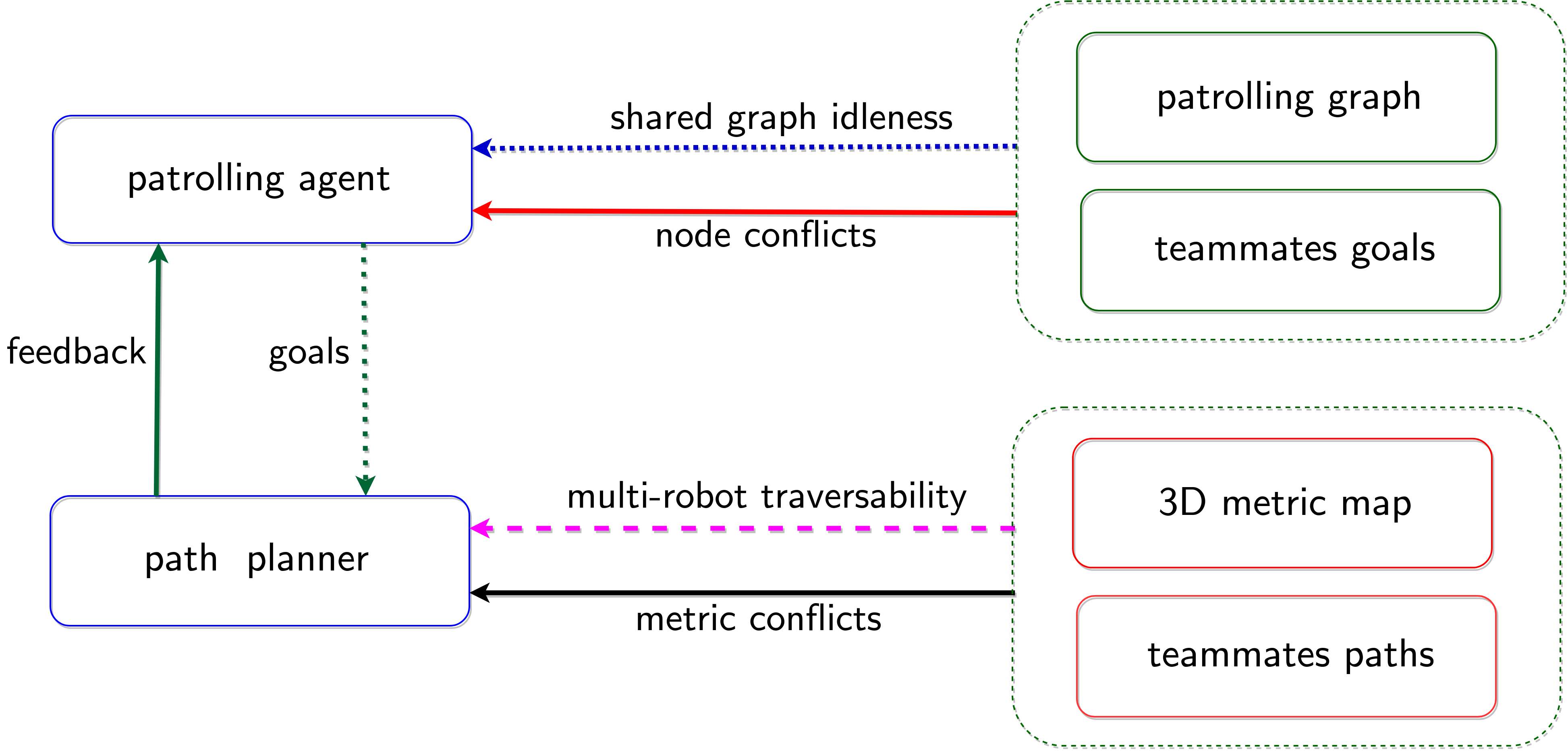
The path planner acts on the metric strategy level (see Figure 3) by computing the best safe path from the current robot position to by using its internal 3D map (see Sect. 7.3)).
The patrolling agent guarantees topological coordination by continuously monitoring and negotiating possibly incoming node conflicts (see Sect. 6). In case multiple robots select the same goal (node conflict), the robot with the smaller travel cost actually goes, while the other robots stop and re-plan towards new nodes.
The path planner guarantees metric coordination by applying a multi-robot traversability function. This induces a prioritized path planning Lavalle-2006 , in which robots negotiate metric conflicts by preventing their planned paths from locally intersecting (see Section 7.2).
The continuous interaction between the patrolling agent and the path planner plays a crucial role. When moving towards , the path planner continuously re-plans the best traversable path till the robot reaches the goal. During this process, if a safe path is not found, the path planner stops the robot, informs the patrolling agent of a path planning failure and the patrolling agent re-plans a new node. On the other hand, every time the path planner computes a new safe path, its length is used as travel cost by the patrolling agent to resolve possible node conflicts.
In our view, the two-way strategy approach allows (i) to simplify the topologically based decision making and (ii) to reduce interferences and manage possible deadlocks. In fact, while the patrolling agent focuses on the most important graph aspects (shared idleness minimization and node conflicts resolution), the path planner takes care of possible incoming metric conflicts due to unmanaged topological edge conflicts. Moreover, where the path planner strategy may fail alone in arbitrating challenging conflicts, the patrolling agent intervenes and reassigns tasks in order to better redistribute robots over the graph. As a result, these combined strategies minimize interferences by explicitly controlling node conflicts and by planning on multi-robot traversability maps.
6 Distributed Patrolling
In this section, we present in detail the patrolling agent algorithm. A pseudocode description is reported in Algorithm 2.
A patrolling agent instance runs on each robot. It takes as input the robot ID, the patrolling graph and the metric map. A main while loop supports the patrolling algorithm (lines 3–22). First, all the relevant data structures and the main boolean variables444We use an “is_” prefix to denote boolean variables. are updated (line 4, see Section 6.1). This update takes into account all the information received from teammates and recasts the distributed knowledge. If the current goal node has been reached (line 5), a broadcast message informs the team (line 6). Then, a new node is planned, a corresponding broadcast message is emitted and the goal position is sent to the path planner (lines 7–9, see Sect. 6.3).
On the other hand, if the robot is still reaching the current goal node, lines 11–20 are executed. If a path planner failure, a node conflict (see Section 6.2), or a node visit (see Section 6.1) occurs on the selected goal (line 11), the patrolling agent first sends a goal abort to the path planner, next broadcasts its decision and then triggers a new node selection (lines 12–16). Otherwise (lines 18–19), a selected message is broadcast and a sleep for a pre-fixed time interval allows the robot to continue its travel towards the selected goal (line 18).
It is worth noting that the condition at line 11 of Algorithm 2 allows each robot to modify its plan at need while reaching the goal. Moreover, a selected message broadcast is repeated at each step555Or at a pre-fixed frequency, after a first selected is broadcast along the way to the current goal. in order to add robustness with respect to network failures.
6.1 Data Update
The Update() function is summarized in Algorithm 3. This is in charge of refreshing the robot data structures presented in Sect. 4. Indeed, these structures are asynchronously updated by callbacks which are independently triggered by received broadcast messages or path planner feedback messages.
Lines 1–3 of Algorithm 3 represent the asynchronous updates of the local instances of the patrolling graph , the point cloud map and the team model . The remaining lines describe how the reported boolean variables are updated depending on the information stored in the team model and received through path planner feedback.
6.2 Node Conflict Management
The concept of topological conflict was defined in Section 5.1. During the patrolling process, a topological node conflict occurs when two or more patrolling agents select the same goal node, which we refer to as contended node. Our strategy resolves a topological conflict by assigning the contended node to the robot which can reach it with the smallest travel cost.
A robot checks for node conflicts by using the information stored in its individual team model (cfr. Sect. 4.6). In this process, it compares its plan with those of teammates. In particular, robot detects a node conflict with robot at node if the following conditions are verified:
-
1.
robots finds in its team model that robot has the same goal, i.e., in .
-
2.
the travel cost is higher than in , or in the unlikely case the travel costs and are equal (robot priority by ID as a fall-back).
When the two above conditions are verified, robot sets the boolean variable is_node_conflict to true (line 4 of Alg. 3), aborts its current goal and re-plans a new node (lines 12–16 of Alg. 2).
If a robot experiences node conflicts for more than a pre-fixed time interval , it enters in a critical node conflict state. In this case, a boolean variable is_critical_node_conflict is set true (line 9 of Alg. 3).
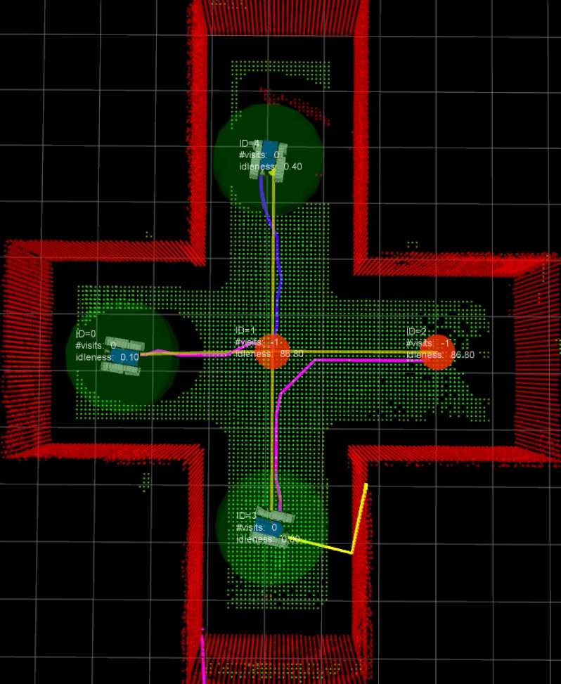
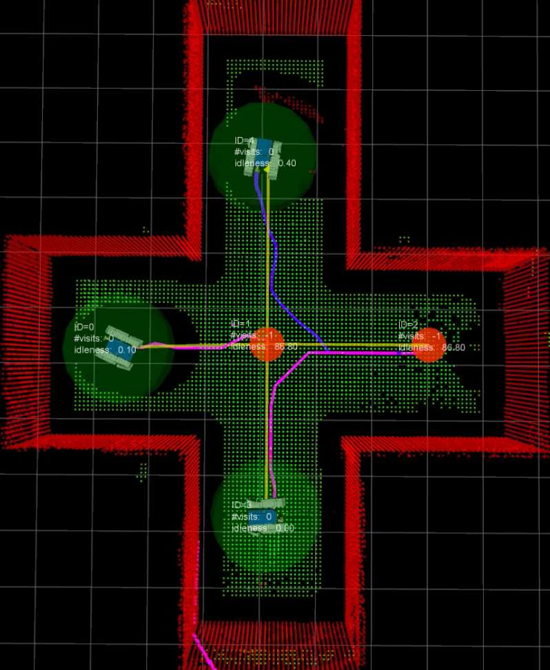
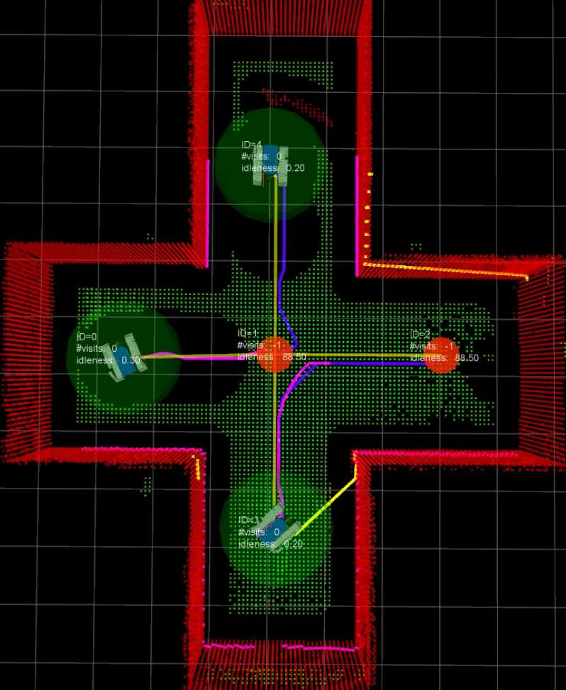
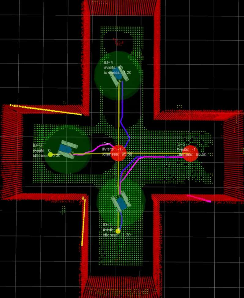
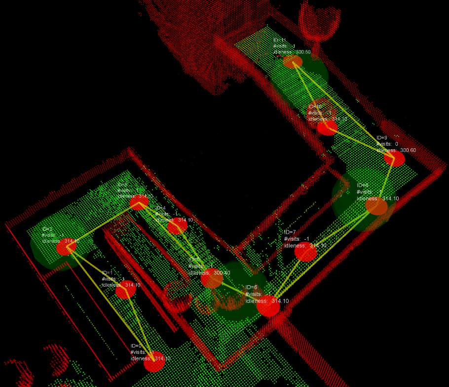
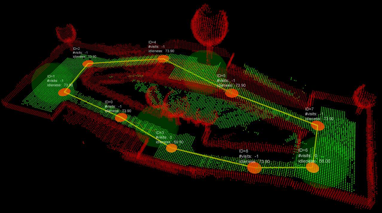
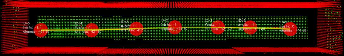
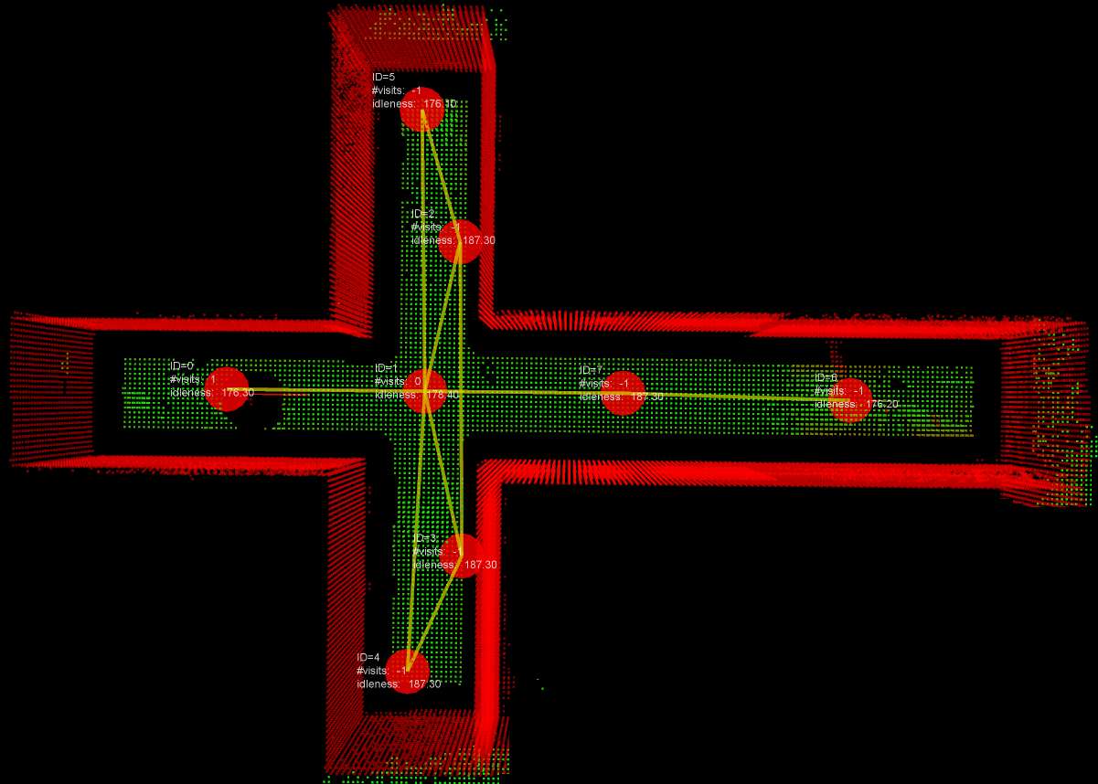
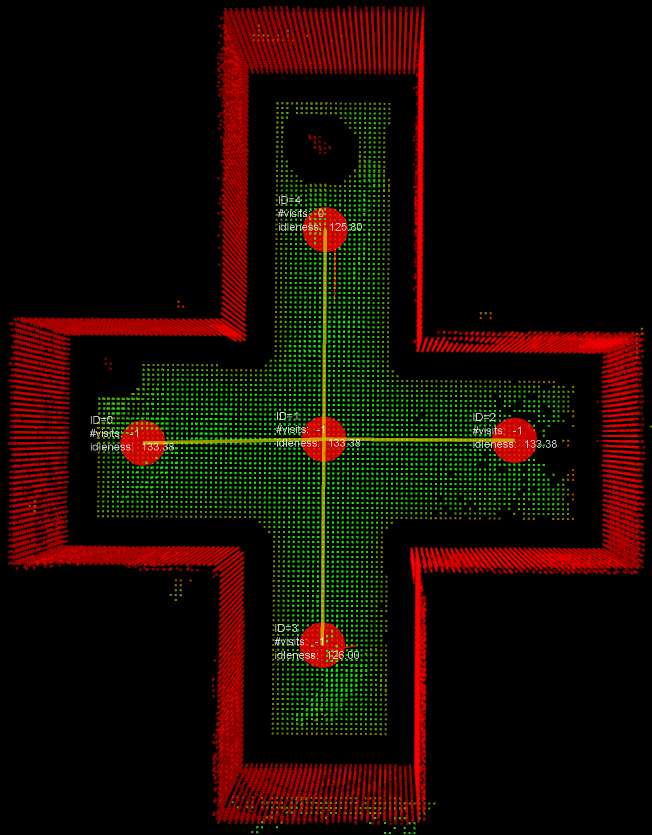
As an example, we report in Fig. 4 a sequence of node negotiations amongst three robots.
6.3 Next Node Planning and Selection
The strategy adopted for planning the next node is described in Algorithm 4. First, the algorithm verifies if a critical condition is occurring (line 2), i.e., if either a critical path planning failure (see Section 7.5) or a critical node conflict is occurring (see Section 6.2). If a critical condition is not occurring (line 3), a search set (i.e., a set of candidate goal nodes) is built (line 5), then the next best node is computed in (line 6). Here, the functions BuildSearchSet() and ComputeNextBestNode() can encode any user-defined strategy with the proviso that must not contain the possible contended node in case is_node_conflict is true.
On the other hand, if a critical condition occurs (line 2), a randomized node selection is performed on the graph (line 3). Such a randomized selection is used to crucially discharge the planner from any search space restriction (line 5) and selection strategy (line 6). In fact, these may trap the algorithm in a “local minimum”, where the planner continuously selects a temporary unreachable node as goal.
For instance, a search space restriction (line 5) at graph depth (aka reactive strategy) makes the robot stuck idle when reachable nodes are available only at depth .
On the other hand, “local minima traps” can be envisioned on the top of any deterministic selection strategy (line 6) by introducing a virtual objective function which combines together the explicit user-defined “utility” function666In our case, this depends on the idlenesses of the nodes. and the navigation cost-to-go. Indeed, a local minima trap occurs when an obstruction blocks the robot way towards the node with the highest “utility”. For instance, the obstruction “disconnecting” can be a door suddenly closed or a group of teammates persisting in front of the robot. In such cases, a randomized selection technique results in an effective method to escape local minima in terms of computational efficiency, generality and reliability barraquand1992numerical .
Algorithm 4 can be used as a base to support any online strategy. In this work, as an example, we use a reactive strategy for the implementations of the functions BuildSearchSet() and ComputeNextBestNode(). Such a strategy effectively provides readiness in resolving incoming spatial conflicts and in making decisions on rapidly changing patrolling graphs. Specifically, we build as the current node neighbourhood (line 4, Algorithm 4) and select as best node the one in with the highest idleness estimate (line 5, Algorithm 4). This implementation can be considered as an improved version of the Conscentious Reactive algorithm Portugal-2013a . In fact, here we explicitely manage interferences and spatial conflicts in order to prevent deadlocks.
For efficiency reasons, in the function ComputeRandomNode() (line 3, Algorithm 4), the randomized strategy first selects a node at a graph depth one, then it linearly increases the depth of the search with time if the current critical condition is not readily escaped. In order to preserve probabilistic completeness, the randomized selection is performed on the full patrolling graph after a number of consecutive failures.
Two important observations are in order. First, local minima (critical conditions) are detected thanks to the continuous interaction between the patrolling agent and the path planner. Second, the presented Algorithm 2 puts into effect a cooperative strategy if the adopted ComputeNextBestNode() function selects the next node on the basis of the shared idleness representation (cfr. Sect. 4.5). The latter allows to avoid inefficient actions, such as selecting a goal node recently visited by a teammate.
7 Multi-robot Traversability and Path Planning
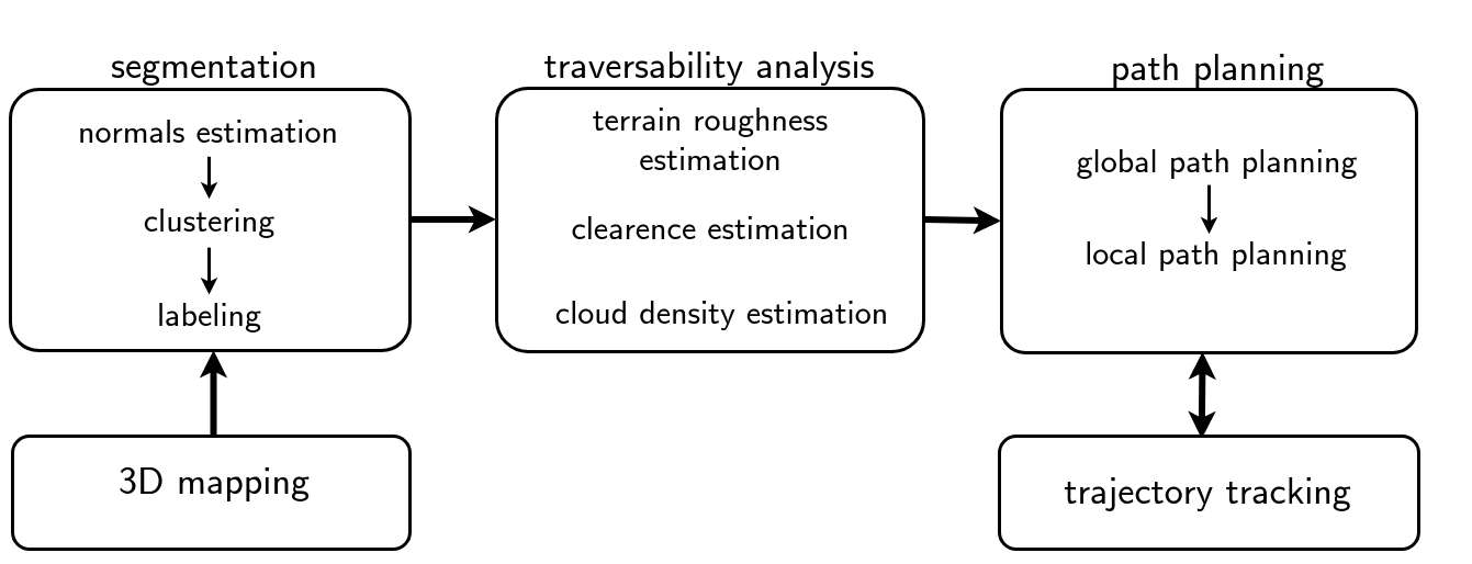
Basing on the metric strategy, the path planner attains local coordination by applying a multi-robot traversability function. This allows to compute a traversable path towards the designated goal node and to locally negotiate metric conflicts. Figure 5 presents the metric level and its main modules, which are described in the following subsections.
7.1 Point Cloud Segmentation
At each new scan, the robot updates its individual 3D map (see Section. 8). Map points are then segmented in order to estimate a traversability of the terrain. First, geometric features such as surface normals and principal curvatures are computed and organized in histogram distributions. Clustering is applied on 3D coordinates of points, mean surface curvatures and normal directions Menna-2014 ; Ferri-2014 . As a result, a classification (labeling) of the 3D map in regions such as walls, terrain, surmountable obstacles and stairs/ramps is obtained. All regions which are not labeled as walls are referred to as non-walls.
7.2 Multi-robot Traversability
The path planner computes a traversable path directly on the segmented non-walls regions of the individual robot 3D map.
Denote with a metric space on . Let and be the center and the radius of a ball , in which we consider a suitably connected neighbourhood of . Each non-wall point is evaluated along with its local neighbourhood and “back-projected” onto a robot pose by using the local surface normal at Krusi-2016 .
For efficiency reasons777The metric level modules must run on the robot main board and share computational resources with other demanding processing nodes Kruijff-2015 ., each robot body is represented by its bounding sphere when computing its clearance from obstacles and teammates. This allows faster computations for both the traversability analysis and the path planner (see Section. 7.5). In this context, the path planner can restrict the path search in a “projection” of on a 3D Euclidean space888At this stage, we found this approach to perform very well in practice without significantly limiting the robot manoeuvres in the tested scenarios..
Traversability for each robot is computed as a cost function on its 3D map. To this end, each neighbourhood of a map point is evaluated along with its local geometric features and segmented aspects (see Sections 7.1).
In particular, the traversability cost function is computed as
|
|
(3) |
Here the weight depends on the point classification, is the multi-robot clearance (defined below), depends on the local point cloud density and measures the local terrain roughness (average distance of outlier neighbour points from a local fitting plane).
In order to attain a look-ahead path planning with local coordination and obstacle avoidance behaviours, the traversability analysis of a robot is “informed” with the current positions and planned paths of its teammates.
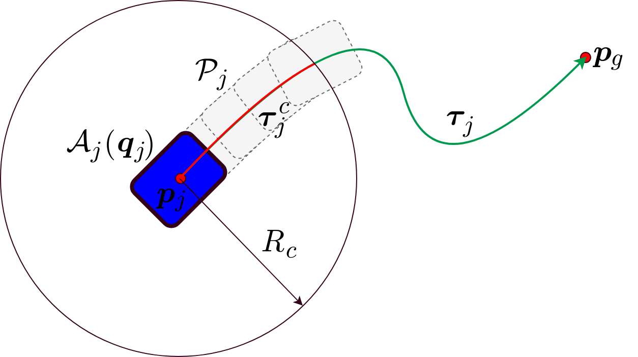
In particular, let and respectively denote the current pose and position of robot . is the compact region occupied by robot at . Denote with the current planned path, which leads robot to its assigned goal configuration. Moreover, let be the portion of which keeps the robot centre within , a closed ball of radius centred at (see Fig. 6). Here is a pre-fixed cropping radius.
The future trail of robot is defined as the compact region:
| (4) |
In other words, the future trail of robot is the 3D region the robot would cover along up to a maximum distance from (see Fig. 6). If no goal is assigned, one has .
Robot computes the multi-robot clearance as its clearance at with respect to a) obstacles sensed at its current position 999Here we include the segmented obstacles in the map and the most recent nearby obstacle points which have been detected by the rangefinder and are not segmented yet in the map . b) each teammate future trail , with , such that . Here, is a pre-fixed radius greater than . Specifically, when computing , any teammate future trail that is distant more than from the current robot position is discarded.
The multi-robot traversable map is obtained from the current map by suitably thresholding the function and collecting the resulting points along with their traversability cost (see Fig. 7).
It is worth noting that the multi-robot traversability allows the implementation of a prioritized path planning which takes into account prospective robot interactions Lavalle-2006 . Planning priorities are implicitly assigned to teammates according to the time order in which their planned paths are received and integrated in the robot traversability map . In this process, the balls and are used in order to locally bound the coordination on the traversable map.
It should be emphasized that, in case of strong communication delays, the sole knowledge of teammates’ positions cannot be used to attain a safe robot navigation. In such a case, the multi-robot traversability (with its integrated knowledge of the teammates prospective paths) allows to attain metric coordination by (i) minimizing interferences and (ii) safely steering each robot ahead of time towards its goal. Moreover, given the fact that robots “reserve” their motion space (by concurrently laying down prospective paths over the multi-robot traversability), node conflicts are often prevented.
7.3 Path Planning and Windowed Search Strategy
For implementation and efficiency reasons we make use of a global and a local path planners. Given a set of 3D waypoints as input, the global path planner is in charge of a) checking the existence of a traversable path joining them and b) minimizing a mixed cost function along the computed path (see Sect. 7.4). This mixed cost function combines together the multi-robot traversability cost (see Sect. 7.2) along with an optional task dependent cost function.
Once a global path solution is found, the local path planner continuously replans a traversable path that safely drives the robot from its current configuration to the first configuration of that intersects a sphere of radius centred at . This allows the path planner to more readily react to possible dynamic changes in the environment.
Both the global and the local path planners capture the connectivity of the configuration space by using a sampling-based approach. The path search is restricted to a “projection” of on a 3D Euclidean space (Sect. 7.2). In fact, the path planner computes trajectories directly on the traversability map.
A tree is expanded on the traversability map by using a randomized A* approach Ferri-2014 ; Diankov-2007 . The start node and the goal node are computed as the projections of the start and goal robot positions on . is used as root in order to initialize . The tree expansion at the current node proceeds as follows
-
1.
The clearance is computed at the position corresponding to (see Sect. 7.2)
-
2.
A safety radius at is computed as the minimum between and a pre-fixed maximum robot step;
-
3.
A set of neighbours is created by collecting all the points of the traversable map that fall in a ball of radius centred at the position of ;
-
4.
A subset of neighbours in are randomly selected as new children of by using a probability inversely proportional to the corresponding traversability cost (this biases the expansion towards more traversable regions);
- 5.
-
6.
The computed A* cost-to-go is used for inserting with priority the new child in a search queue;
-
7.
The element of the search queue with the minimum cost-to-go is selected as next node to expand.
In this process, a kd-tree is used for fast nearest neighbour search. The algorithm ends when a child node is found close enough to the desired goal position.
In order to further improve the efficiency and the response time of both the local and global path planners, a windowed search strategy has been implemented around the basic path planner. Let be the Euclidean line segment joining the assigned start position and the goal position . Each time the global/local path planner is called to compute a new path:
-
1.
First, the path search is restricted in the subset of points of the traversable map , where is a box with medial axis containing . Roughly speaking, this region is shaped as a narrow corridor with a longitudinal axis aligned to .
-
2.
If a path cannot be found within , then it is searched within a new region which is built by suitably growing along its axes of symmetry.
-
3.
If the path search fails then this process is repeated by incrementally growing the search region until a pre-fixed number of attempts is reached.
In order to preserve the probabilistic completeness of the basic path planning algorithm, the last attempt uses the full traversable map as search region. For sake of safety, the most updated traversability map is considered as input at each planning attempt.
In this process, the different attempts allow the robot to process different world “snapshots” over time, with the benefit of possibly finding a solution after an initial failed attempt (due to new occurring favourable conditions).
7.4 Mixed Cost Function
The randomized A* algorithm computes a sub-optimal101010The sub-optimality of the solution is due to the used incremental sampling-based approach Karaman-2010 ; Diankov-2007 . path in the configuration space111111As explained in Sect. 7.2, each point of can be associated to a robot pose. by minimizing the total cost:
| (5) |
where and are the start and the goal respectively, and . The cost-to-go function combines together the traversability cost and an optional task dependent function121212This can be used for instance to steer the robot toward regions where an estimated WIFI radio signal strength map returns higher values caccamo2017rcamp .. In particular
| (6) |
| (7) |
where is a distance metric, is a goal heuristic, is the z-coordinate of the node , and are positive scalar weights, is the normalized traversability function, is a small quantity which prevents division by zero and is a normalized task-dependent cost function. The first factor in eq. (6) sums together the distance metric, the A* heuristic function (usually the distance to the goal) and a weighted difference of the z-coordinates of the nodes. The other two factors , and represent a normalized traversability cost and a normalized task-dependent cost respectively, whose strengths can be trade-off by using the weight . Note that for . The normalized task dependent function is typically built with a structure very similar to caccamo2017rcamp .
7.5 Coordinated Path Planning and Message Protocol
The path planner continuously replans a path on the multi-robot traversability map in order to react to possible dynamic changes in the environment. In this process, it uses the most updated map, the knowledge of prospective teammates paths and the current sensory information. A pseudocode description is reported in Algorithm 5. The function PathPlanning is invoked by the path planner every time a new goal is received from the patrolling agent.
Specifically, when a new goal position is designated, the path planner first tries to compute an initial solution (lines 2–9), up to a maximum number of attempts (set to 5 in our experiments). At each failed attempt, it waits for a pre-fixed time interval (line 8), then it retries by using the most updated information (line 3, see Sect. 6.1). If after attempts an initial solution is not found, the path planner communicates its failure to the patrolling agent (line 16) and then waits for a new goal; otherwise, a solution is found and a success message is sent to the patrolling agent (line 13).
Once an initial solution is found, the robot starts moving toward its goal (line 14) along the computed path. In this process, the path planner continuously replans a new path by using the most updated information (lines 11–20). Since the environment is assumed to be dynamic and populated by moving robots, a path planning failure can be verified by the local path planner during its continuous replanning, even after an initial solution is found by the global path planner. In case of failure, the path planner communicates it to the patrolling agent and then a new goal is received (line 12–16, Algorithm 2).
The path planner is managed at the topological level by the patrolling agent, whose decisions (i) support cooperation and coordination with teammates, and (ii) allow to detect and manage deadlocks. In fact, the patrolling agent continuously checks the path planner status and, in case of critical conditions (see Section. 6.3), pre-empts its current task and reassigns it a new goal (lines 12–16, Algorithm 2). In particular, if the path planning keeps on failing for more than a pre-fixed time interval , we say that a critical path planning failure is occurring. This can be provoked by a local minima trap, as discussed in Sect. 6.3. In this case or when a goal is aborted by the patrolling agent (line 12, Algorithm 2), the variable is set to true and the continuous re-planning loop (lines 11–21, Algorithm 5) is stopped.
It is worth noting that, in the initial solution search, the basic wait-retry process allows the robot to process different world “snapshots” over time. In some situations, this works as a virtual traffic-light and it allows teammates to move, reach their goals and free the way. In general, this basic wait-retry process alone is not sufficient to avoid deadlocks. For instance, it is not able to resolve the conflict experienced by two robots moving in opposite directions (e.g. along a narrow corridor) and reciprocally blocking their ways. Indeed, such a case defines a local minima trap for both robots (continuous path planning failures would be generated on both sides). In our approach, many ingredients are used to prevent such deadlocks: the structure of our patrolling agent, the topological and metric coordination (Sect. 5.2), the continuous interaction between the patrolling agent and the path planner. In particular, the ability to detect critical conditions (Sect. 6.3), node conflict resolutions (topological coordination) and the randomized selection strategy allow to escape from local minima traps (e.g. the situation described above).
The path planner continuously publishes the following messages after each plan or re-plan step, as a feedback.
-
•
The path planner status: this message is sent to the patrolling agent in order to inform it if a solution path was found (success) or not (failure), or if the assigned goal has been reached (reached). A success message also includes the navigation cost of the computed path.
-
•
The path message: this is broadcast to teammates and contains the current estimated robot position and the current planned path (see Table 2). These data are essential for computing the multi-robot traversability.
On the other hand, the path planner can receive command messages from the patrolling agent. In particular, a command message contains the current goal node position along with the desired action: go or abort.
8 3D Mapping and Localization
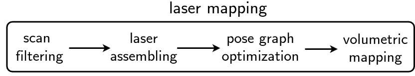
In order to apply the distributed patrolling technique introduced in Section 6, the robots need to localize in a common global reference when moving in the environment. This multi-robot localization is performed against a 3D map which is built prior to the patrolling mission. This map is also used for generating the initial patrolling graph presented in Section 4. In the present system, the prior map and the individual maps of each robot, are built using the pose-graph SLAM pipeline depicted in Figure 8. For the experiments presented in Section 10.2, the maps are generated using the observations from a rotating 2D LiDAR sensor. However, our system is flexible and accepts LiDAR sensors which directly provide 3D information.
Once the prior map has been generated, it is uploaded to each robot participating in the patrolling mission. The multiple robots globally localize themselves using a place recognition strategy based on 3D segment extraction matching dube2017segmatch . During the mission, each robot is responsible of (1) communicating to the other robots its location with respect to the prior map and (2) updating its local 3D volumetric representation of the environment to reflect dynamic changes. The multi-robot localization solution detailed in the present section is inspired from earlier work (dube2017segmatch and dube2017multirobot ) and has been adapted and integrated for fulfilling the needs of our patrolling framework.
In the remaining of this section we describe in more detail the SLAM approach used, the chosen map representation, and the multi-robot localization on the prior map.
8.1 3D Pose-Graph SLAM
In order to generate the prior map and to perform persistent SLAM on each robot, the SLAM system relies on a pose-graph optimization back-end grisetti2010tutorial . The states of our framework are robot poses collected at times . These are estimated by optimizing a negative log-posterior , an error function that sums over a series of constraints . Here, defines the error between the predicted state and the observed state of the system, i.e., , and the information matrix. The SLAM framework implements three different types of constraint that are summed up in :
-
•
prior constraints ,
-
•
odometry constraints , and
-
•
scan-matching constraints .
Prior constraints can be created by using global localization information as described in Section 8.3.Secondly, odometry constraints define pose displacements of consecutive robot locations by fusing IMU and wheel odometry measurements using an Extended Kalman Filter as described in kubelka2015robust . Scan-matching constraints are finally obtained using Iterative Closest Point (ICP) to match the current scan against all previous scans within a sliding time window where is the current time and is the chosen fixed time window. The output of the ICP algorithm is a set of rigid transformations which can directly be translated into pose-graph constraints.
Let be the sequence of robot poses acquired in the time interval . Denote by and respectively the set of pairs of timestamps for which odometry and scan-matching constraints exist over the same time interval . The error function is then defined as
| (8) |
on the sliding time window. This error function is finally minimized using the Gauss Newton algorithm and the robot trajectory is updated with the optimization result.
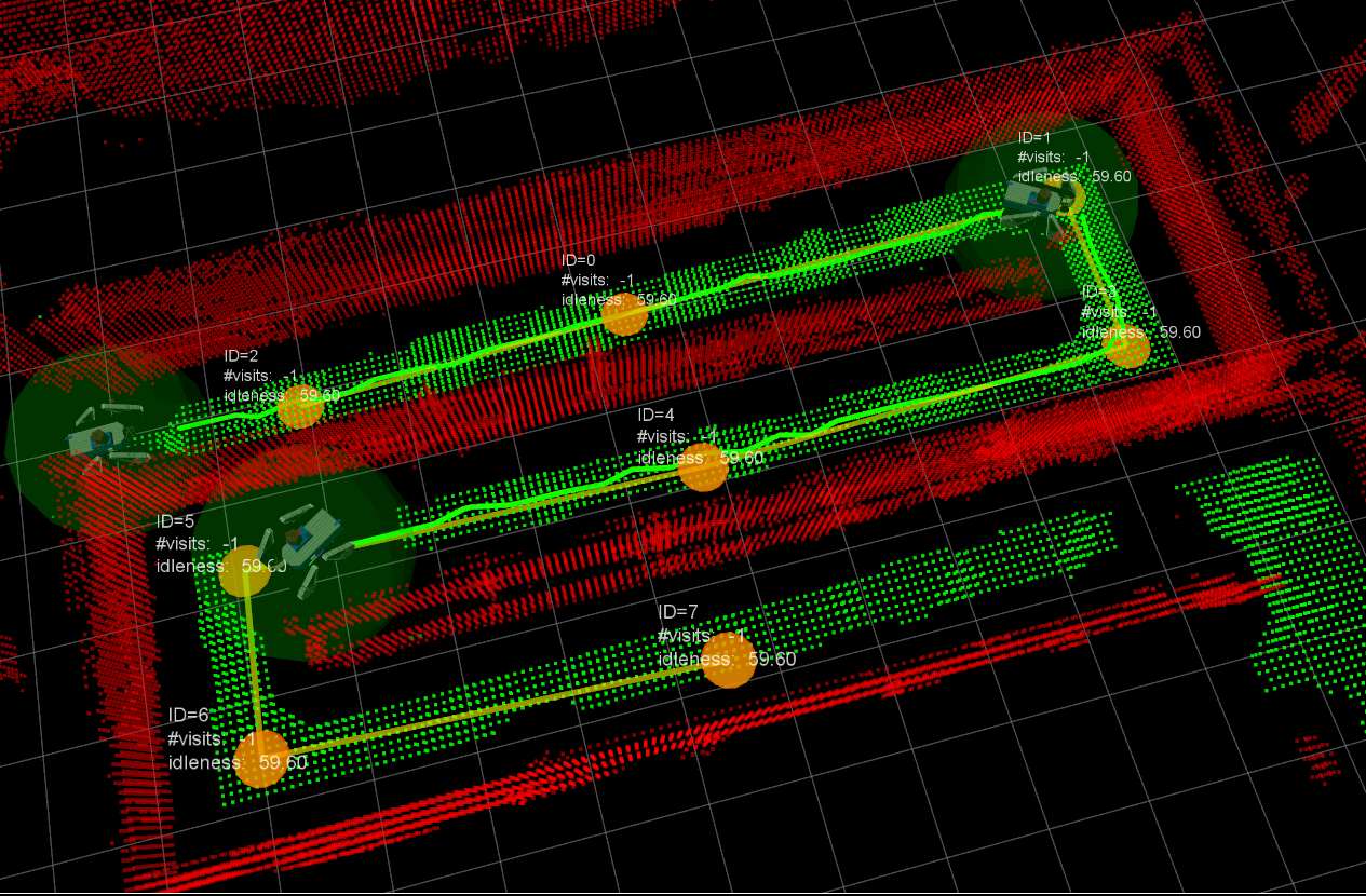
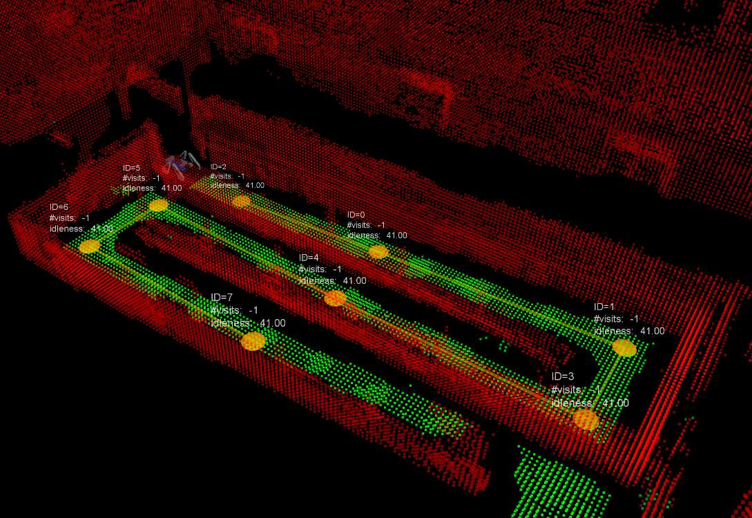
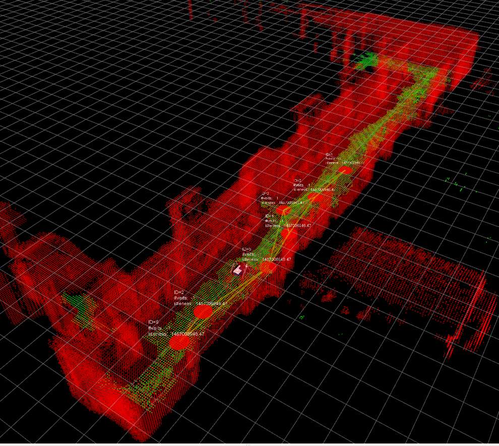
The pose-graph model therefore serves as an implicit estimation of the robot trajectory and map. The latter can explicitly be generated, in the form of an OctoMap, by projecting individual scans from the optimized robot poses into the global frame of reference. An example of this 3D representation is illustrated in Figure 9.
8.2 OctoMap representation
We select the OctoMap Hornung-2013 representation for modelling occupied and free space explicitly. The OctoMap representation exhibits several advantageous properties for multi-robot applications. This representation first allows to register mapping data from different sources in a common frame of reference, enabling the distributed patrolling strategy introduced in Section 6. Moreover, this probabilistic framework accounts for dynamic objects which can be filtered over multiple observations due to the explicit modelling of free space using ray-casting. The OctoMap can be obtained by either loading an existing map and applying potential online extension, or building it online using our LiDAR-based SLAM approach.
In order to use this representation for navigation and patrolling, a ‘clamping policy’ is adopted by setting a lower and upper bound on the log-likelihood of the occupancy estimate in the OctoMap. The final decision about occupancy is made by thresholding this bounded estimate which ensures that the 3D map representation can quickly adapt to changes in the environment131313The dynamic update of the OctoMap and its reactive behaviour is demonstrated in a video https://youtu.be/caECYcYdrgo.
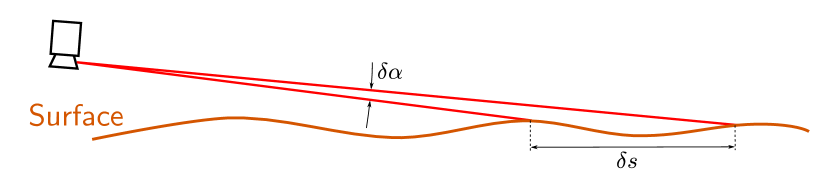
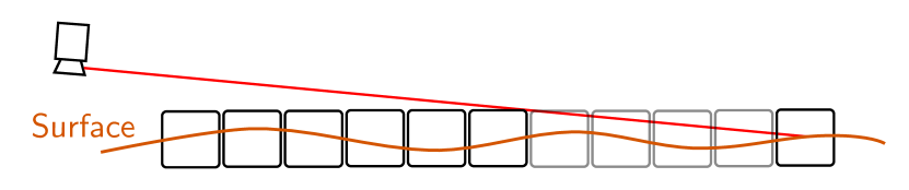
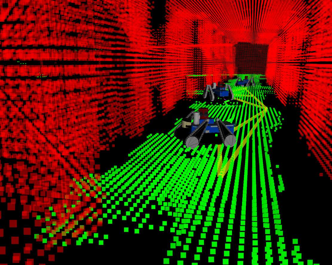
For the Unmanned Ground Vehicle (UGV)s used in our experiments, the LiDARs are mounted at low heights which requires an adaptation over the classic OctoMap approach. As displayed in Fig. 10, the motivation behind this adaptation is that a low angle of incidence relative to the ground may cause voxels to be falsely marked as free space which is in turn critical for the traversability analysis introduced in Section 7.1–7.2. We therefore limit the angle of incidence at which ray-casting can lower the occupancy probability of voxels to a lower bound .
The center-points of occupied OctoMap cells are thus used for traversability analysis as shown in Section 7.2.
8.3 Multi-robot localization
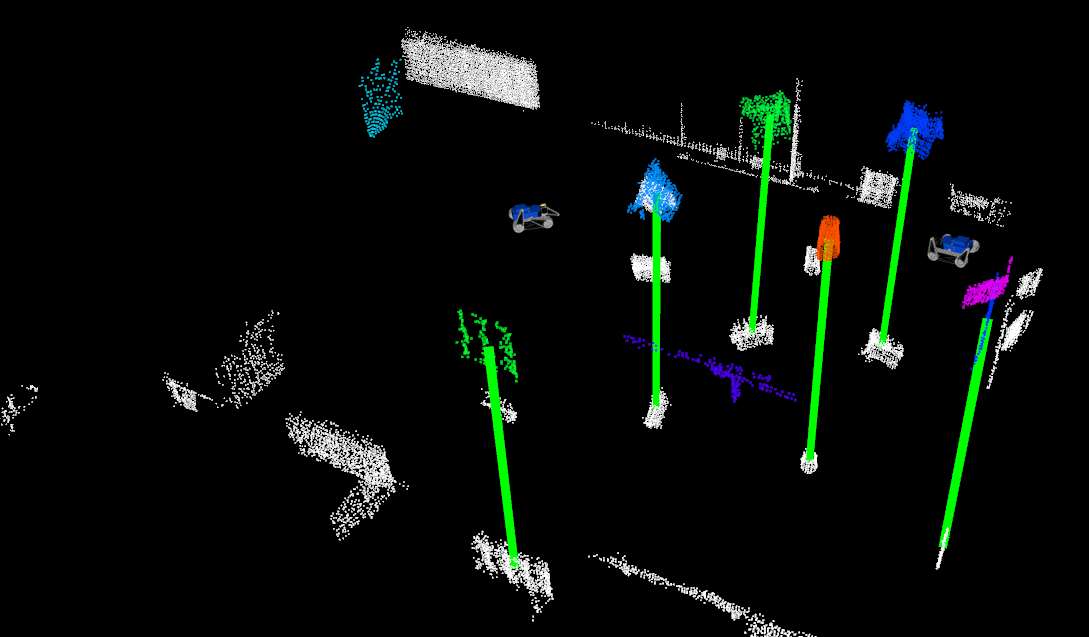
At the beginning of a patrolling mission, the global location of each robot is estimated using the SegMatch algorithm dube2017segmatch . Specifically, 3D point cloud segments are extracted from the prior map and all local maps by applying ground-plane removal, followed by Euclidean clustering with a growing distance douillard2011segmentation . Eigen-value based features are then extracted in order to uniquely describe each segment weinmann2014semantic . Candidate segment matches are identified between each local map and the target map by considering the nearest neighbours in feature space. An transformation is finally obtained for each robot by selecting the largest group of consistent candidates using RANSAC with a resolution . Figure 11 illustrates a localization example with the consistent group of matches depicted with green vertical lines. The paremeters used in this algorithm throughout the experiments are presented in Table 4.
Each robot uses this localization information for initializing its own SLAM algorithm, as presented in Section 8.1. Given that an unique prior map is shared amongst all robots, scan-matching factors are generated by performing ICP against this shared map. Thus, ensuring that the multiple robots are globally localized in real-time and in a common reference frame, enabling the multi-robot patrolling technique presented in this work. This localization paradigm is able to account for changes in the environment, if a sufficient amount of structure is similar, enabling ICP to converge to correct solutions.
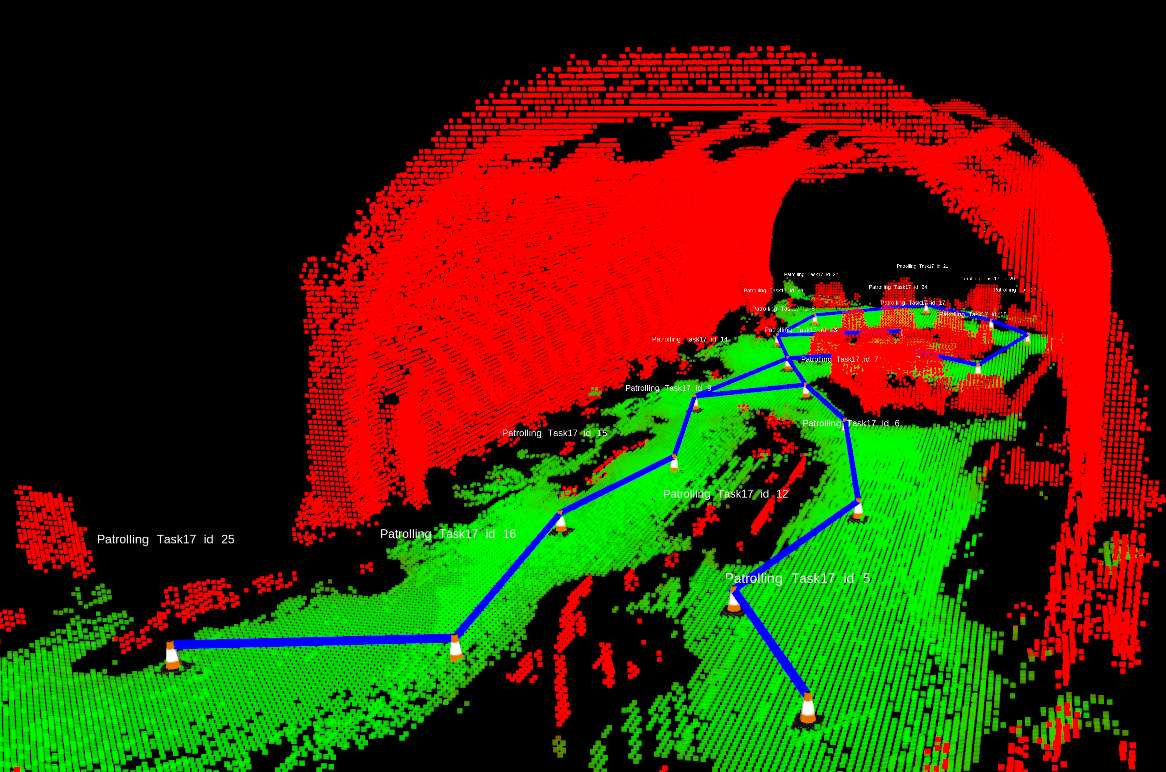
9 Patrolling Graph Building
This section briefly presents two procedures for building a patrolling graph: the first (interactive) takes as input a set of Points Of Interest (POIs) selected by the user on the 3D interface; the second (automatic) automatically computes the patrolling graph from an history of robot trajectories.
9.1 Patrolling Graph from a User-assigned Set of Waypoints
In the interactive procedure, a set of POIs (or waypoints) are selected by the user on the map. These are potentially considered as patrolling graph nodes. Then, an algorithm automatically adds an edge between each pair of nodes that satisfy the following conditions:
-
1.
the Euclidean distance between the corresponding points is smaller than a maximum distance (set to in our experiments);
-
2.
the line segment connecting and does not intersect the map;
-
3.
the line segment between the positions and has an elevation angle smaller than a maximum angle (we set this to );
-
4.
a traversable path between the node positions exists.
The first condition is added for containing the branch factor of each node and avoid too long travels between nodes. The second condition checks if the line segment intersects the ground or an obstacle. The second and third conditions together avoid connecting nodes which belong to different floor levels or which can be joined by a too steep passage.
If some of the points are not connected, they are not considered as nodes, the user can move or delete them, and then repeat the procedure. In this process, kd-trees are efficiently used in order to perform collision checking.
9.2 Patrolling Graph from a Saved History of Robot Trajectories
The automatic graph building procedure is based on the approach presented in Menna-2014 . First, each input robot trajectory is initially discretized via uniform sampling, in order to obtain a sparse sequence of poses. Then, each resulting sequence is accumulated in a suitable space-partitioning data structure, where the robot orientation is disregarded. Next, a voxel grid filter is applied to this data structure to reduce the number of points stored therein.
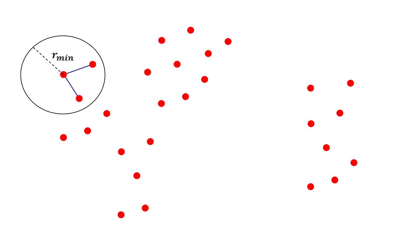
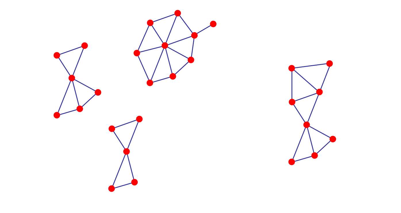
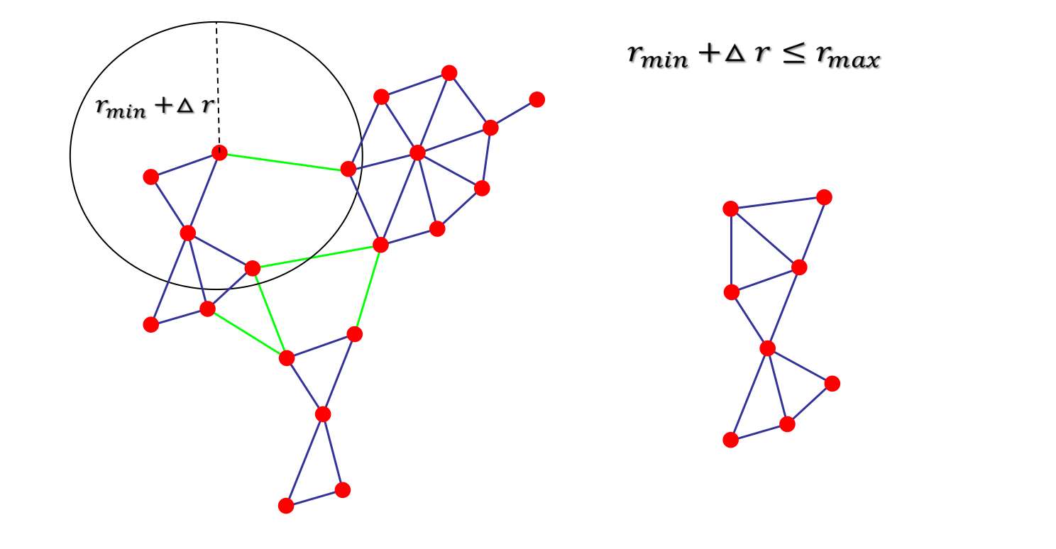
For each resulting point in the filtered data structure a node is generated. Connections among nodes are established as follows. A preliminary procedure is applied to the filtered data structure to find a set of distinct connected components (see Figure 12b). This procedure searches for all the nearest neighbours of a query point in a given radius (see Figure 12a). Finally connected components are linked together through an iterative radius search procedure, where at each iteration, the value of the radius is incremented in order to ensure connectivity (see Figure 12c).
10 Results
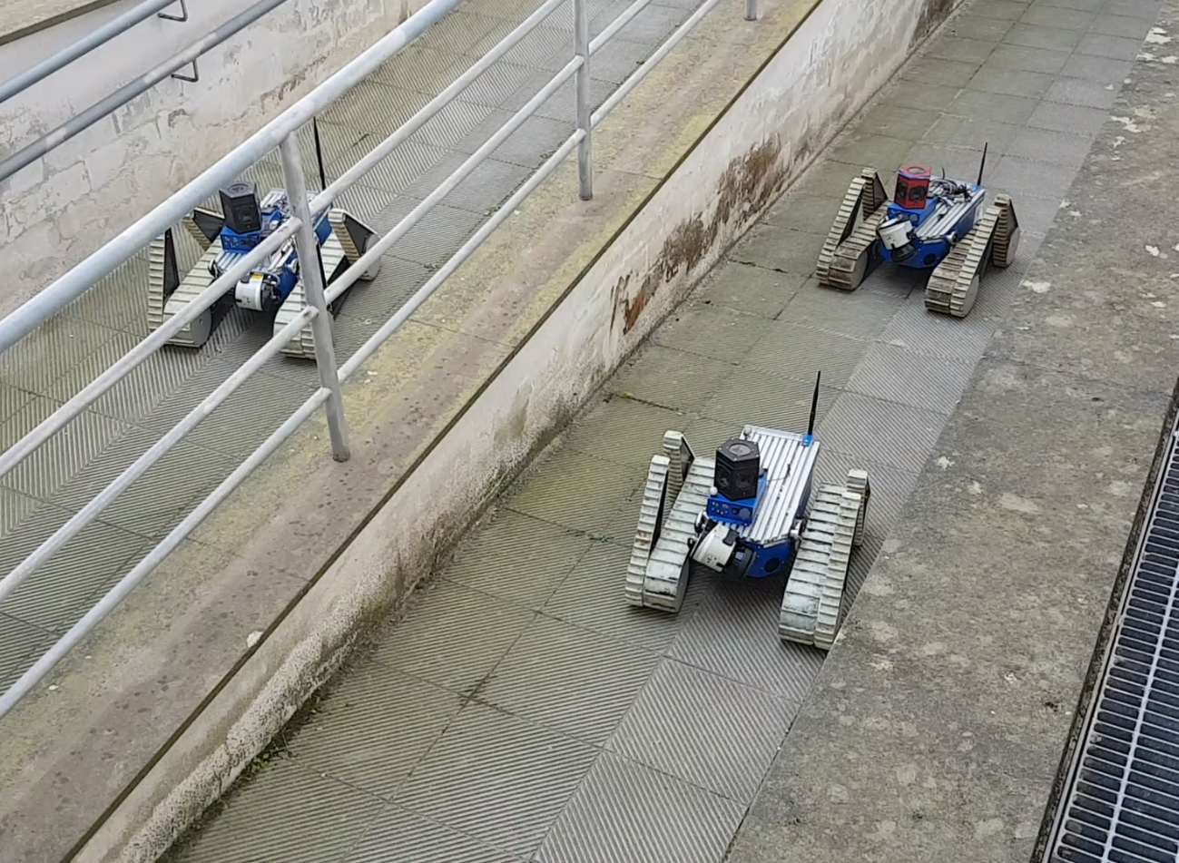
This section presents the results we obtained with an implementation in 3D. We validated the proposed strategy on the TRADR UGV robots Kruijff-2015 (cfr. Fig. 13), both in simulations and real-wold experiments. These vehicles are skid-steered and satisfy the path controllability assumption (see Sect. 4.1). Amongst other sensors, the robots are equipped with a spherical camera and a rotating laser scanner.
We considered 3D scenarios which are typical for our TRADR UGVs (see Sect. 1). Here, interferences are very likely and the UGVs need to navigate by (i) avoiding conflicts in narrow passages, (ii) performing reliable traversability analysis and coordinated path-planning, (iii) reliably localizing in 3D while simultaneously updating and extending the input 3D metric map. In these scenarios, there is typically an high ratio between team size and patrolling graph size.
For convenience, we report in Tables3–4 the list of the main parameter values we used both in simulations and experiments.
| Description | Symbol | Value | |
|---|---|---|---|
| Robot max linear velocity speed | \rdelim}63mm[Path Planning] | ||
| Robot bounding radius | |||
| Robot safety distance | |||
| Future trail crop radius | |||
| Radius for considering future trails | |||
| Path planning waiting time | |||
| Critical path planning failure time | \rdelim}63mm[Patrolling] | ||
| Critical node conflict time | |||
| Patrolling sleep time | |||
| Patrolling main loop rate | |||
| Idleness message broadcast period | |||
| Team model expiration time |
| Description | Symbol | Value | |
|---|---|---|---|
| Maximum laser range | \rdelim}83mm[3D SLAM] | ||
| Scan maximum density | |||
| Scans in Sliding window estimation | |||
| knn surface normal computation | 20 | ||
| ICP error metric | point-to-plane | ||
| Prior noise model | |||
| Odometry noise model | |||
| Scan matching noise model | |||
| OctoMap resolution | \rdelim}43mm[OctoMap] | ||
| OctoMap occupancy thresholds | |||
| OctoMap hit / miss probabilities | |||
| OctoMap min angle ground removal | degrees | ||
| Region growing distance | \rdelim}33mm[SegMatch] | ||
| Number of nearest neighbours | |||
| RANSAC resolution |
All the algorithms are implemented in C++ (cfr. Sect. 14.1). ROS is used as middleware. The code has been designed to seamlessly interface with both simulated and real robots. This allows to use the same code both in simulations and experiments. An open source implementation is available141414 https://gitlab.com/luigifreda/3dpatrolling..
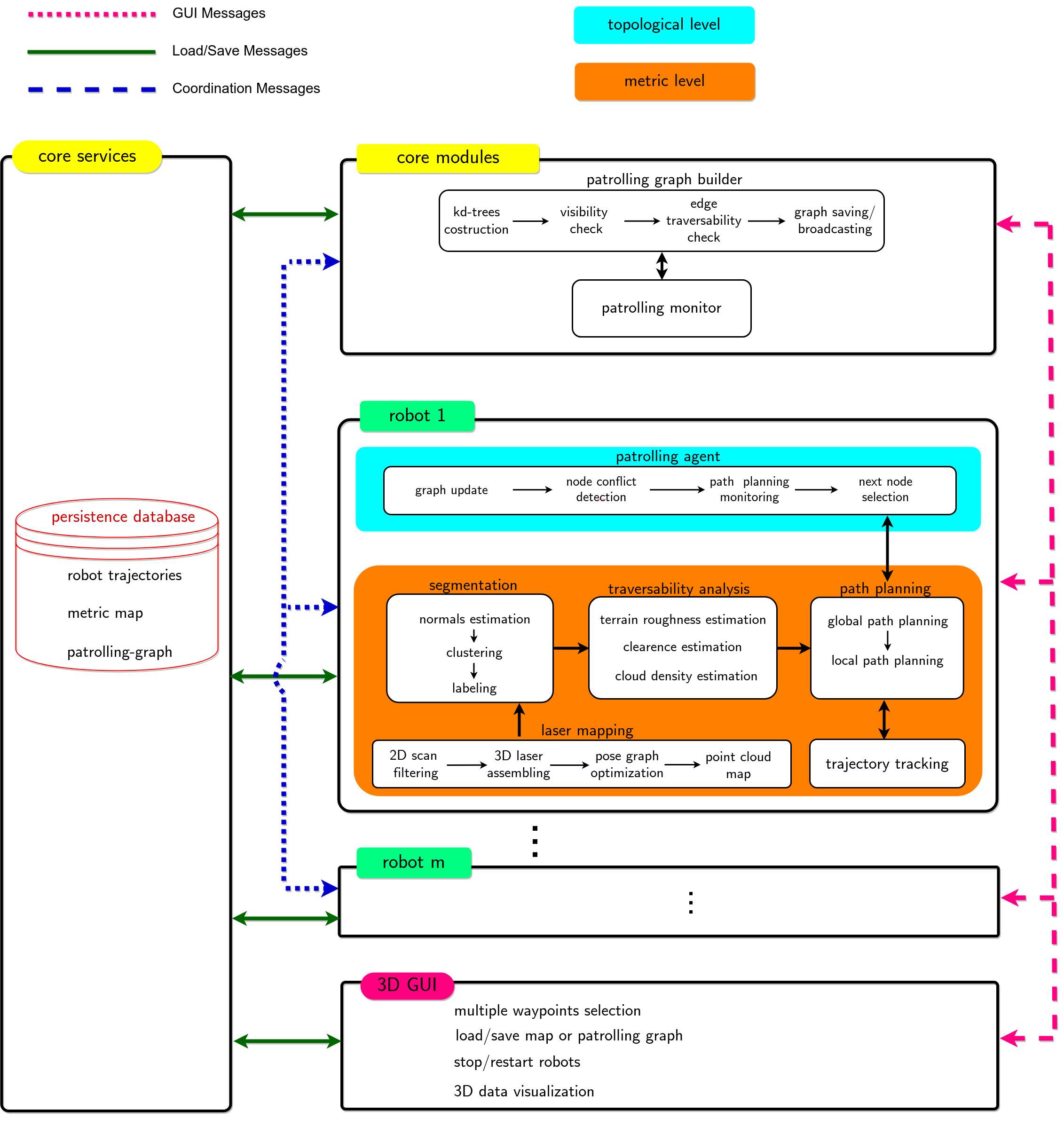
A functional diagram of the presented multi-robot system is reported in Fig. 14. This is detailed in Sect. 14.2.
10.1 Simulation Experiments
This section presents simulation results obtained with the V-REP simulation framework vrep . V-REP allows to simulate laser range finder and odometry noise. Grousers have been added to the simulated robot tracks in order to obtain realistic robot interactions with the terrain.
For convenience, we have adopted a single-core ROS architecture during our simulation runs. A different and more efficient network architecture is used for the real-world experiments (see Section 10.2). In simulation, we introduced a fixed delay of in the publishing of each broadcast message.
In this work, since the focus is on patrolling aspects, we do not consider the articulated tracks during motion planning151515This aspect can be managed for instance as proposed in Zimmermann-2014 or Colas-2013 .
We perform simulations with teams up to four TRADR robots. While this is a typical team size in the considered SaR applications, it is mainly a limitation from the V-REP simulations which is computationally very demanding. To face this limitation, our setup distributes the V-REP simulations, and the ROS nodes performing SLAM, segmentation, traversability analysis, path planning and patrolling on distinct computers. However, in our setup, V-REP is not able to stably simulate more than four robots under realistic conditions. On the other hand, the presented multi-robot patrolling strategy is fully distributed and the implementation of its coordination protocol does not require special hardware.
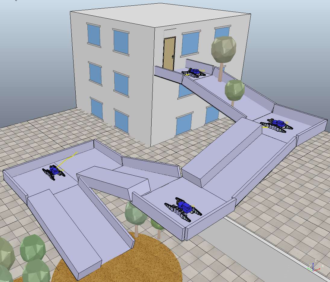
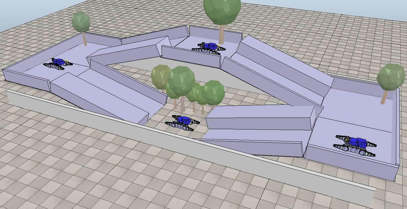
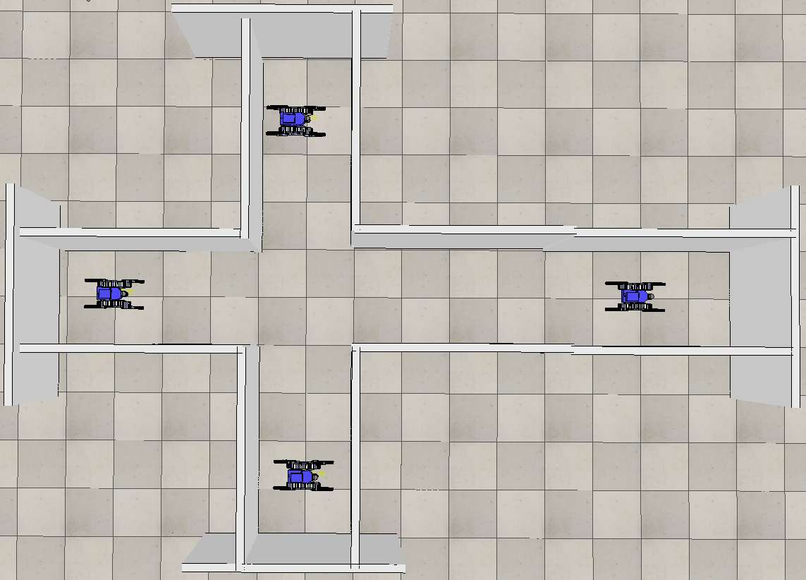
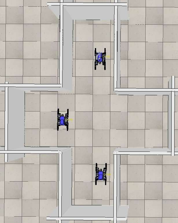
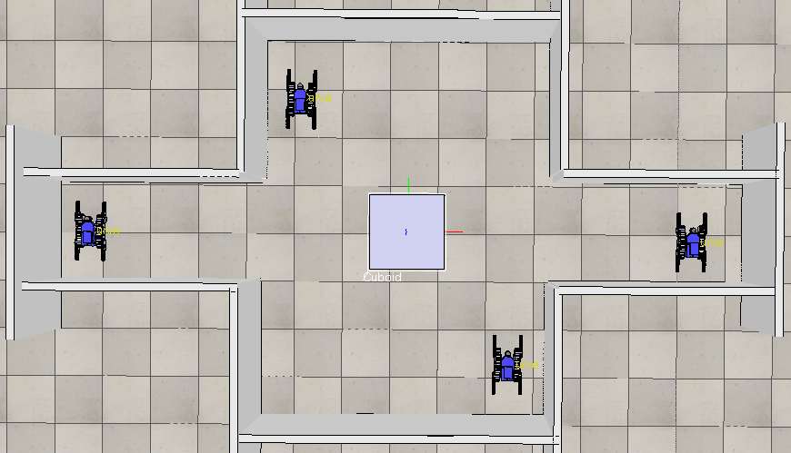
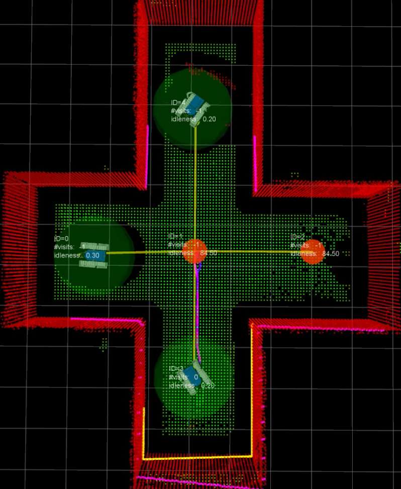
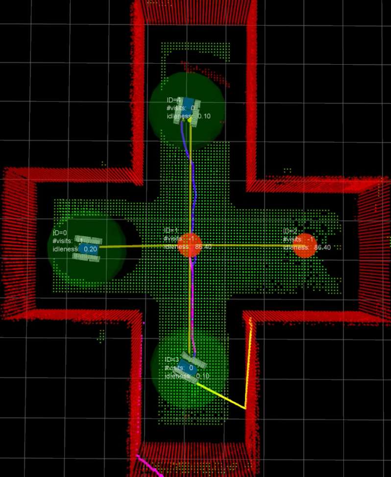
The simulated scenarios are depicted in Figures 15, 16 and 17. In particular, Fig. 16 collects the used multi-floor scenarios, while 15 and 17 show the single-floor scenarios. In our view, the scenarios of Fig. 17 can be considered as representative topological types of environment junctions, which may be found in common single-floor scenarios. In particular, we simulated the challenging scenario “small crossroad” with teams of three robots and four robots. Some videos of the simulations and further details are publicly available161616 https://sites.google.com/a/dis.uniroma1.it/3d-cc-patrolling/.
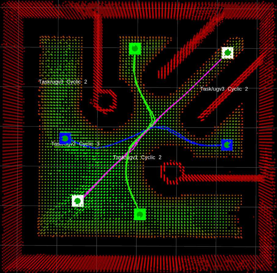
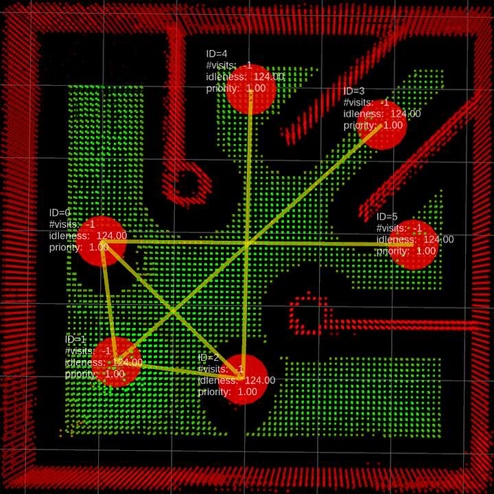
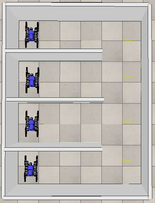
In a first stage, we separately evaluated the multi-robot traversability in order to show how it improves the behaviour of the path-planner. To this aim, we used the challenging scenario reported in Fig. 15a and assigned to the each robot one of the distinct cyclic paths shown in Fig. 15b. Here, each robot was required to move back and forth between its two assigned waypoints by using only the path planner (no patrolling graph and no patrolling agent). We compared the behaviour of the path planner with and without the multi-robot traversability. In the scenario of Fig. 15b, we run 10 simulations, each one lasting 10 minutes. We observed that a team of three robots, which used the basic path planners, always got stuck in a deadlock (around the intersection of the three cyclic paths). On the other hand, path planners and multi-robot traversability succeed in nicely coordinating the robots without congestions or deadlocks171717Two simulation videos are available on our website and show these behaviour..
In similar environments, characterized by narrow crossroads, we obtained comparable results. In general, when considering only the path planner, we observed that the multi-robot traversability improves the navigation ability of a robot team. This becomes particularly evident in scenarios where significant congestions and deadlocks may occur. Clearly, there are complex cases which cannot be managed by the multi-robot traversability, given the high complexity of the general multi-robot path planning problem Lavalle-2006 . Nonetheless, we empirically show that our two level coordination strategy (multi-robot traversability plus patrolling agent) can resolve conflicts and prevent deadlocks in complex patrolling scenarios.
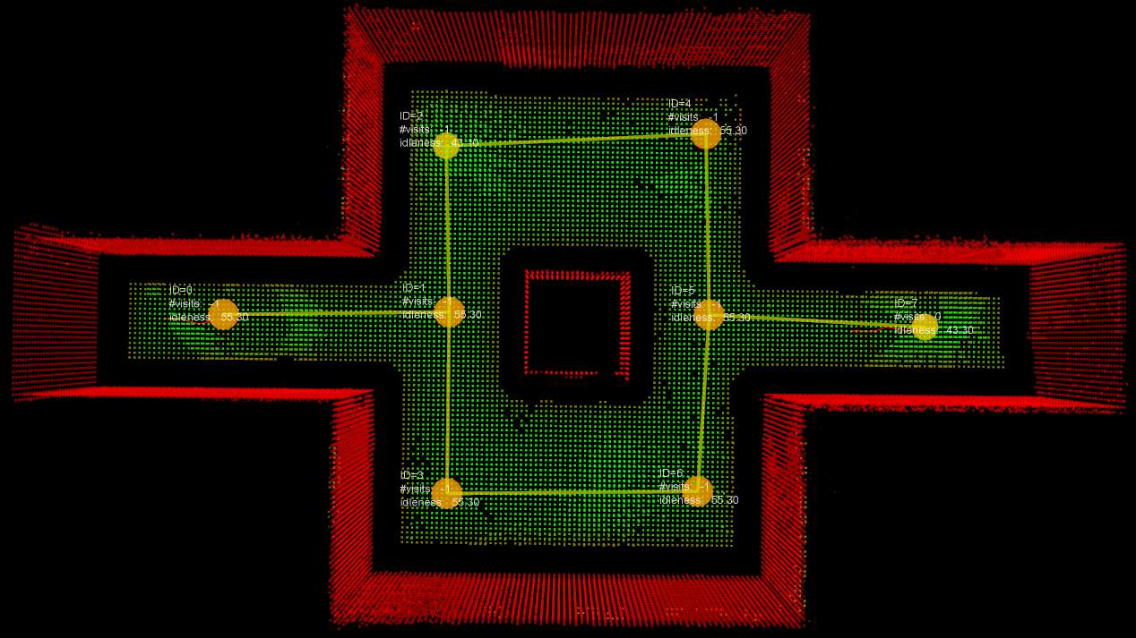
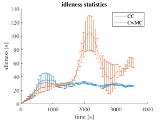
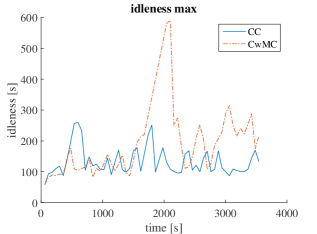
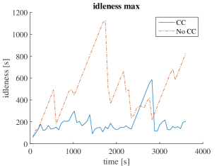
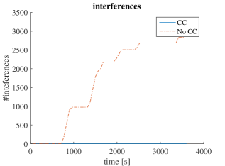
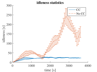
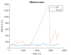
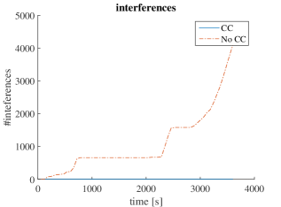
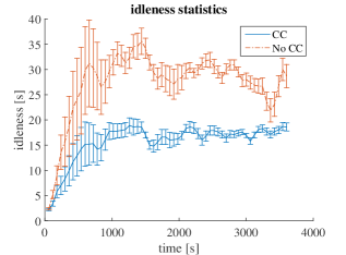
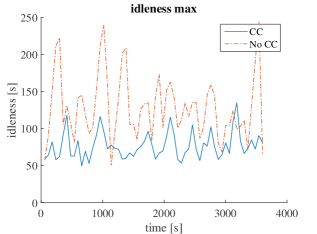
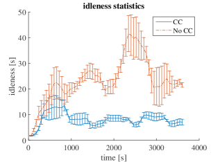
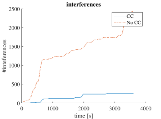
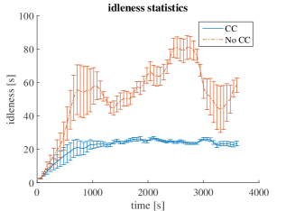
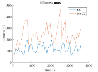
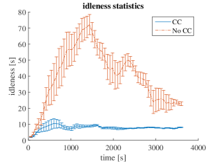
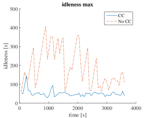
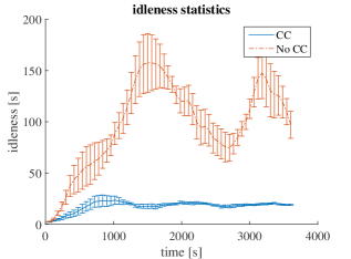
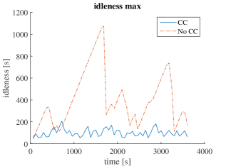
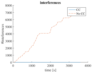
In a second stage, we evaluated the (full) two level coordination strategy. To this aim, we used as performance metrics the idleness statistics introduced in Section 4.2 and the total number of occurred interference events. In particular, we continuously measured in a moving-window the average graph idleness , its standard deviation and its maximum value , where denotes the current time and we selected . In particular, we considered a moving-window in order to better observe transient dynamics. We found that a time width of 600 was a good compromise to significantly capture both transients and regime behaviours.
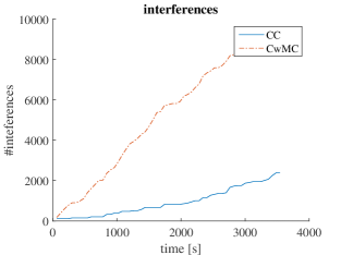
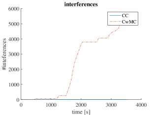
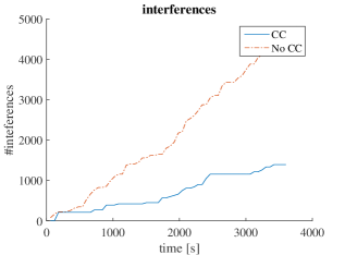
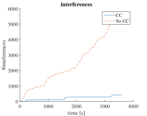
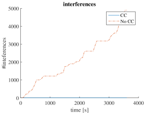
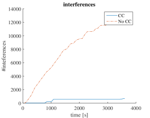
Moreover, we counted the total number of interference events that are broadcast by the robots when their centres get closer than the safety distance (see Section 5.1). These checks are executed at and recorded at a pre-fixed frequency of . Indeed, such an interference measure overall represents how long the robot team experienced interference and conflicts181818Since V-REP simulations are computationally demanding in our setup, the simulated robots were not able to move in real time and their motions were very slow (this can be observed in our simulation videos on our website). As a result, when robots got in interference, they persisted in such conditions for longer times with respect to a normal real time simulation..
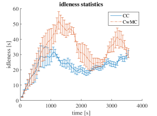
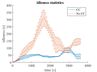
We compared the patrolling strategy presented in this paper (see Algorithms 2–4) with two simplified versions of it. The first simplified strategy is obtained by only disabling the multi-robot traversability (metric coordination). The second one is obtained by disabling node conflict management (topological coordination) and shared idleness estimation (cooperation), but it preserves metric coordination. In the remainder of this paper, we refer to the full patrolling strategy as CC strategy (Cooperation plus Coordination), to the first simplified strategy as CwMC strategy (Cooperation without Metric Coordination) and to the second simplified strategy as No-CC strategy. As explained in Sect. 6.3, in this work, we selected a reactive strategy for the implementations of the functions BuildSearchSet() and ComputeNextBestNode() of Algorithm 4.

For each simulated scenario, we report the results obtained with a simulation run lasting one hour. In all the runs, we used the same software deployment, i.e. we distributed ROS nodes and V-REP in the same way. It is worth noting that, in each scenario, we observed consistent results across simulation experiments started with different initial robot poses, as already reported in other works Farinelli-2016 .
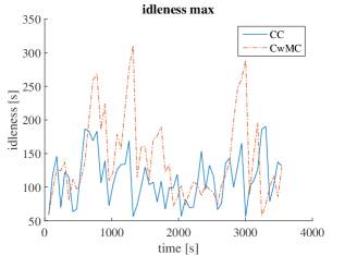
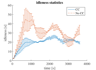
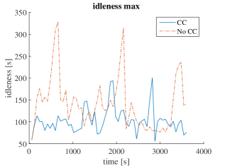
The obtained performance metrics are shown in Figures 18, 19, 20 and 21. In each sub-figure, we report (left) a plot of the moving average idleness of the graph along with its standard deviation, (center) the maximum idleness observed in the moving time-window and (right) the total number of observed interferences up to the current time.
In particular, we compared the CwMC and CC strategies in the challenging scenarios three-ways (now using the patrolling graph in Fig. 15c) and crossroad. These simulations allow to highlight the performance improvements that can be provided by the multi-robot traversability when patrolling robots need to negotiate challenging space conflicts.
As can be observed, the performance metrics of the CC strategy overall present better trends in all the scenarios. In Fig. 18, results confirm the superiority of combining the multi-robot traversability with the path planner. In other scenarios, the comparisons between CC and CwMC returned small improvements or comparable idleness performances191919Which we do not report here in order to reduce space.. Notably, in the multi-floor scenarios, the number of interferences of CC is constantly zero in the two-floor ring (Fig. 19b), while its value grows202020This is not visible in the plot but it was observed by inspecting the recorded data. to during the second part of the simulation in the multi-floor ramp (Fig. 19a). In general, the big spikes which characterize the max idleness curves in Fig. 19 correspond to an inefficient team deployment over the graph or to the occurrence of challenging conflicts. In the latter case, the conflicts are constantly controlled and solved by the CC, while they produce a big performance degradation in the case of the No-CC strategy. Indeed, it is possible to observe a significant correlation between the maximum idleness and the average idleness which are shown in Fig. 19.
Another important result can be observed on both the idleness statistics curves shown in Fig. 19: The moving average idleness of the CC is overall smaller and much less dispersed than the correspondent curve of No-CC. Similar results are obtained in the case of single-floor scenarios (see Figures 20 and 21). We observed that the multi-floor ramp, the single-floor corridor and the crossroad are very challenging scenarios for the No-CC strategy since the robots continuously obstruct each other while trying to reach the ends of the graph. On the other hand, the CC strategy succeeds to avoid interference and direct negotiation of metric conflicts by mainly using node conflict management and shared idleness in order to properly redirect and redistribute robots over the graph. Clearly, in these challenging cases, all the encountered metric conflicts usually subject the engaged robot path planners to an high and useless computational load with a strong performance degradation.
It should be emphasized that no deadlocks occurred during all our simulation runs. The two-level strategy succeeded in safely governing the robot behaviour, arbitrating conflicts and suitably distributing the robots over the graph.
10.2 Real-world Experiments
|
The real-world multi-robot system is implemented in ROS by using a multi-master architecture. In particular, nimbro_network nimbro is used for efficiently transporting ROS topics and services over a WIFI network. Indeed, nimbro_network allows to fully leverage UDP and TCP protocols in order to control bandwidth consumption and avoid network congestions. This capability along with a comparative testing of different ROS multi-master architectures made the TRADR consortium adopt nimbro_network Kruijff-2015 ; worstdrDr63 ; worstdrDr64 .
We used the same C++ code in order to run both simulations and experiments (cfr. Sect. 14.1). Only ROS launch scripts were adapted in order to specifically interface the modules with the actual multi-master nimbro_network transport layer.
We performed patrolling experiments with real UGVs aiming at showing the applicability and portability of the developed software in the real 3D world. We tested our strategy with teams of two and three robots in different environments. Figure 22 shows two of the considered scenarios along with their maps and patrolling graphs. In particular, the CC strategy described in Sect. 6.3 was tested on the TRADR UGVs and a satisfactory behaviour was achieved. Some videos of the performed experiments and further details are publicly available212121 https://sites.google.com/a/dis.uniroma1.it/3d-cc-patrolling/.
Experiments confirmed that map visualization is the most demanding networking functionality of the system. This is only required on the 3D GUI of the central core if a user want to monitor patrolling actitivities (see Fig. 14). In this context, nimbro_network transport layer was crucial for achieving almost smooth map data transfers. Only the broadcast of compact coordination messages is required in order to implement the presented CC strategy.
During the experiments, we observed that some of the path and selected messages were delayed or lost. Such situations temporally provoked a patrolling performance drop, due to a locally degraded coordination. Nonetheless, nor the operation activity of the system was crucially affected, neither major congestions or deadlocks occurred. These aspects are further discussed in Sect. 11.
It is worth noting that the windowed search strategy presented in Section 7.3 proved to work very well in practice. Most times, the path planner finds a path at the first attempt with the advantages of (i) conveniently reducing the search space 222222In these cases, the path planner only considers the most interesting and useful part of the traversability map. and (ii) reducing on the average the computational load generated by the path planner.
11 Discussion
In this section, we shortly discuss the presented patrolling approach in terms of network resilience and scalability. Then, we present some lessons learnt in deploying our system in real-world scenarios.
11.1 Network Resilience
The proposed multi-robot system is distributed and avoids any centralized arbitration scheme, which would represent a critical point of failure.
In the proposed strategy, the communication protocol was designed with redundant messages and an idleness synchronization scheme which support the shared knowledge representation (see Sect. 4.5).
In particular, at topological level, a selected message is periodically broadcast (see Sect. 4.5). This redundancy adds robustness with respect to sporadic selected message losses. In fact, if a single selected message is lost, two robots may move towards the same node until new selected messages arrive and allow them to resolve the node conflict. Clearly, if a significant amount of messages is lost, each robot plans its actions relying on an incomplete representation of the world state. In such case, idleness estimates are not cooperatively updated, moreover, coordination and cooperation smoothly degrade given the missed shared information and teammates decisions. When the network is completely down, each robot greedily performs an independent patrolling mission by avoiding teammates (see below) and solving critical path-planning failures with goal pre-emption and continuous re-planning.
At metric level, the path-planners continuously re-plan paths and correspondingly broadcast path messages (see Table 2). In this way, each multi-robot traversability map is continuously updated. If many path messages are lost, robots will not stop but will independently proceed towards their goals, avoiding each other thanks to the combination of the continuous re-planning with a low-level proximity checker232323This laser proximity checker inhibits forward velocity commands when a close front obstacle is detected by the laser.. It is worth noting that the metric coordination enforced by the multi-robot traversability is locally bound by the radius (see Sect. 7.2). This implies that a correct multi-robot traversability could be computed even if robots were only able to exchange path messages within a limited communication range .
Additionally, even if not presented in this work, it is worth mentioning that the system can make use of the communication-aware path planner presented in caccamo2017rcamp . This drives each robot towards better WIFI connectivity regions while planning a path towards the designated goal.
11.2 Scalability
In our experiments, the number of robots was limited by V-REP242424In our setup, V-REP is not able to stably simulate more than four robots under realistic conditions (cfr. Sect. 10.1). and the real TRADR UGVs available. Nonetheless, we observed that increasing the number of robots tends to improve the patrolling performance even in challenging situations, as shown for instance by the average graph idleness curves in Fig. 20.
Additionally, we observed that, under some conditions, the robot team tends to create dynamic regions where agents patrol more often. This is a nice behaviour already observed in other works Portugal-2016 , without recurring to an explicit space decomposition and allocation. In our case, this behaviour is induced by an explicit management of interference and conflicts (topological and metric coordination).
In terms of network bandwidth consumption, our approach is not demanding and could be scaled up to many robots. In fact, the data size of the messages reached, visited, planned, selected, and aborted is very contained. On the other hand, even if path and idleness messages convey vector data252525The path and idleness message sizes actually depends on the number of patrolling graph nodes., their broadcast frequencies are lower. In particular, path messages are broadcast on path planning updates, which typically occur at time-varying frequencies higher than . Moreover, idleness messages are broadcast according to a pre-fixed frequency . If required, selected messages could also be broadcast at a pre-fixed frequency. In this regard, the user can control such broadcast frequencies and trade-off between bandwidth consumption and system robustness.
As the number of robots grows, local high densities of robots may form. In this case, the number of coordination “interactions” may increase in a large group of close robots facing a challenging space conflict (e.g. a narrow crossroad). Specifically, such robots may need to exchange more coordination messages in order to resolve node conflicts and converge in the negotiation of new goals. We already observed such challenging situations in the experimented 3D scenarios. Nonetheless, the robots always succeeded in nicely redistributing over the patrolling graph in a reasonable amount of time. In this regard, we would like to note that both metric coordination and topological coordination tend to prevent the formation of local high densities of robots.
11.3 Lesson Learnt in Real World Deployment
During this research and the TRADR experience Kruijff-2015 , we learnt the following main lessons through numerous real world deployments.
First, a robust 3D SLAM was required in order to enable multi-UGV operations in 3D dynamic environments over long-term missions. In fact, an accurate multi-robot localization is crucial to enable consistent spatially-registered cooperation and coordination. In some situations, we experienced that our rotating laser system was not stiff enough and driving over rough terrain resulted in noisy point clouds. Therefore, a dense RGBD mapping could open the way to a more accurate point cloud segmentation and traversability analysis. In this regard, the use of a multi-modal SLAM approach which processes both RGBD and laser information could be beneficial.
Second, a distributed knowledge representation and a robust coordination protocol is crucial in order to attain multi-robot collaboration over unreliable network infrastructures. Our framework achieves this through redundant messages and information synchronization mechanims. In this regard, we found some of the nimbro_network features (e.g. forward error correction, adaptive image compression rate and current network quality visualization) to be highly beneficial worstdrDr63 ; worstdrDr64 .
Third, we discovered that interferences and conflicts are very likely in disaster scenarios. In order to effectively cope with these problems, high-level decision making and low-level path planning must be tightly coupled. This is implemented in our two-level coordination strategy. In this context, metric coordination and topological coordination favour each other in a virtuous circle. In fact, when robots “reserve” their motion space by laying down prospective paths over the multi-robot traversability (metric coordination), teammates part away and, therefore, node conflicts are often prevented. On the other hand, when node conflicts are resolved (topological coordination), robots are redistributed over the patrolling graph and, therefore, generally pushed away from each other (preventing interferences).
12 Main Characteristics of the Strategy
Before presenting our conclusions, we summarize the main characteristics of the presented strategy.
Coordination (avoid conflicts):
-
The proposed patrolling strategy is distributed.
-
Interferences and conflicts are explicitly managed.
-
Metric conflicts are managed by the path planner by continuously replanning over the multi-robot traversability. This mechanism implements a prioritized path planning Lavalle-2006 which takes into account prospective robot interactions.
-
Topological node conflicts are detected and resolved by the patrolling agent.
-
Metric coordination and topological coordination favour each other in a virtuous circle (see Sect. 11.3).
Cooperation (avoid inefficient actions): a shared idleness representation supports any optimization strategy in the selection of the next node (see Sect. 4.5). This allows to avoid that a patrolling agent selects a goal node recently visited by a teammate.
Decision making:
-
Decision making relies on a tight coupling between the patrolling agent and the path planner. In particular, the patrolling agent continuously monitors the path planner and accomplishes goal pre-emption and replanning when critical conditions are detected (see Sect. 6.3). Additionally, path lengths computed by the path planner are used to negotiate conflicts.
-
Our strategy can be used as a base to develop any online patrolling solution. A wide range of user-defined strategies could be easily encoded in the best node selection (lines 5–6, Algorithm 4).
Network:
-
Redundant messages and information synchronization mechanisms add robustness with respect to network failures (see Sect. 11.1).
13 Conclusions
This works presented a distributed approach for multi-robot patrolling. We focused on aspects that are typically overlooked in the literature, such as avoiding conflicts and deadlocks in spaces shared by multiple UGVs, considering full 3D environments, traversability analysis, coordinated path planning, and real validation in 3D scenarios. Some of these aspects are summarized in Sect. 12.
In particular, we developed a comprehensive framework for multi-robot patrolling dealing with all the inherent design aspects, from high-level cooperation and decision making, to low-level coordination and path planning. We improved upon the state-of-the-art methods by developing a two-level coordination strategy, which crucially takes into account the necessary tight coupling between topological and metric decision making. In this regard, both topological and metric coordination allow to explicitly minimize interference and conflicts, which crucially affect UGVs activity. We experienced that this approach allows to effectively cope with the typical challenges involved when a team of UGVs is deployed in a disaster scenario.
The presented two-way coordination strategy is general and can be used as a base to develop new strategies for optimizing the patrolling graph idleness and ensuring space conflicts negotiation.
Our multi-robot patrolling algorithm is fully integrated with a 3D SLAM algorithm, traversability analysis and coordinated path planning. This enables our system of ground robots to operate in 3D.
We demonstrate competitive performance in both simulation and real world experiments, enabling robots to simultaneously operate in realistic simulation and in real world experiments. The obtained results show that the Coordination plus Cooperation strategy was superior than our baseline throughout all performance measures, i.e., mean idleness, max idleness, spread of idleness and inference events. Notably, when using the CC strategy, no deadlocks were observed during our experiments and the number of interferences was always significantly reduced (or zeroed in some cases). Moreover, we observed that the multi-robot traversability is able to improve the patrolling team behaviour in the most challenging scenarios, where space conflicts crucially affect robot activities. As discussed in Sect. 11.2, our approach offers good scalability properties both in terms of network bandwidth consumption and performance (the latter to be further validated with larger robot fleets).
We publish the source code of the presented approach with the aim of providing a useful tool for researchers in the Robotics Community.
In the future, we plan to increase the number of robots simultaneously operating in real world experiments262626Recurring to simpler and more affordable robotic platforms is required.. Furthermore, we wish to investigate on patrolling prioritization with heterogeneous robot fleets. In this context, exploration of “unknown” environments given a topological prior (i.e., a topological map used as a patrolling graph) seems a promising research direction. Furthermore, it would be beneficial to integrate explicit dynamic updates of the patrolling graph. Finally, integration of a multi-robot SLAM algorithm, enabling map-sharing and map-persistence over the whole operation is a promising avenue for scaling the real-world operation to larger areas.
Acknowledgements.
This work was supported by the European Union’s Seventh Framework Programme for research, technological development and demonstration under the TRADR project No. FP7-ICT-609763.14 Appendix
14.1 Code Implementation
For the implementation of the patrolling agent algorithm, we used the C++ ROS package patrolling_sim as a starting point patrollingsim ; Portugal-2016 . This is specifically designed for 2D patrolling tasks. It was used as a starting skeleton architecture providing core functionalities (such as graph management utilities). We significantly modified the core of this package in order to manage 3D data, implement our new patrolling agent algorithm, interface the agent module more tightly with the path planner and the 3D GUI in our network architecture.
An open source implementation of our framework is available272727 https://gitlab.com/luigifreda/3dpatrolling..
14.2 Software Design
A functional diagram of the presented multi-robot system is reported in Fig. 14. The main blocks are listed below.
The robots, each one with its own ID , have the same internal architecture and host the on-board functionalities which concern decision and processing aspects both at topological level and at metric level. According to Sect. 4.5, each robot maintains and updates an instance of the patrolling graph and of the metric map in its internal memory.
The core services, hosted in the main central computer, manage the multi-robot system persistence database and allow specific modules to load/save map, trajectories and patrolling graphs from/into the central database (for re-using relevant data along different missions).
The core modules, also hosted in central computer, include the patrolling graph builder and the patrolling monitor. The first builds a patrolling graph from a user assigned set of waypoints or from a saved history of robot trajectories. The built patrolling graph is then distributed to all the robots and saved in the central persistence database. The patrolling monitor continuously checks the current status of the patrolling activities and records relevant data for monitoring and benchmarking.
The multi-robot 3D GUI, hosted on one OCU (Operator Control Unit), is based on RVIZ and allows the user (i) to select multiple waypoints which can be fed to the path planners or to the patrolling graph builder (ii) to visualize relevant point cloud data, maps, and robot models (iii) to stop/restart robots when needed (iv) to trigger the loading/saving of maps and robot trajectories (v) to realign the current map of a selected robot to a loaded map.
The architecture is fully distributed without centralized coordination mechanisms. In particular, each robot hosts an instance of the patrolling agent and of the path-planner.
As shown in Fig. 14, the various modules in the architecture exchange different kind of messages. These are grouped in the following types.
-
•
Coordination messages: these are exchanged amongst robots for sharing knowledge and decisions, in order to attain cooperation and coordination. For convenience, the patrol monitor records an history of these messages.
-
•
GUI messages: these are exchanged with the 3D GUI and include both control messages and visualization data.
-
•
Load/save messages: these are exchanged with the core services and contain both loaded and saved data.
References
- (1) Acevedo, J.J., Arrue, B.C., Díaz-Báñez, J.M., Ventura, I., Maza, I., Ollero, A.: Decentralized strategy to ensure information propagation in area monitoring missions with a team of uavs under limited communications. In: 2013 International Conference on Unmanned Aircraft Systems (ICUAS), pp. 565–574 (2013)
- (2) Acevedo, J.J., Arrue, B.C., Maza, I., Ollero, A.: A distributed algorithm for area partitioning in grid-shape and vector-shape configurations with multiple aerial robots. Journal of Intelligent & Robotic Systems 84(1), 543–557 (2016)
- (3) Agmon, N., Kaminka, G.A., Kraus, S.: Multi-robot adversarial patrolling: Facing a full-knowledge opponent. CoRR abs/1401.3903 (2014)
- (4) Agmon, N., Kraus, S., Kaminka, G.A.: Multi-robot perimeter patrol in adversarial settings. In: ICRA, pp. 2339–2345 (2008)
- (5) Agmon, N., Sadov, V., Kaminka, G.A., Kraus, S.: The impact of adversarial knowledge on adversarial planning in perimeter patrol. In: Proceedings of the 7th International Joint Conference on Autonomous Agents and Multiagent Systems - Volume 1, AAMAS ’08, pp. 55–62. International Foundation for Autonomous Agents and Multiagent Systems (2008)
- (6) Ahmadi, M., Stone, P.: A multi-robot system for continuous area sweeping tasks. In: ICRA, pp. 1724–1729 (2006)
- (7) Aksaray, D., Leahy, K., Belta, C.: Distributed multi-agent persistent surveillance under temporal logic constraints. IFAC-PapersOnLine 48(22), 174–179 (2015)
- (8) Andrade, R.d.C., Macedo, H.T., Ramalho, G.L., Ferraz, C.A.: Distributed mobile autonomous agents in network management. In: Proceedings of International Conference on Parallel and Distributed Processing Techniques and Applications (2001)
- (9) Baran, P.: On distributed communications networks. IEEE transactions on Communications Systems 12(1), 1–9 (1964)
- (10) Barraquand, J., Langlois, B., Latombe, J.C.: Numerical potential field techniques for robot path planning. IEEE transactions on systems, man, and cybernetics 22(2), 224–241 (1992)
- (11) Bereg, S., Caraballo, L.E., Díaz-Báñez, J.M., Lopez, M.A.: Resilience of a synchronized multi-agent system. ArXiv e-prints (2016)
- (12) Cabrita, G., Sousa, P., Marques, L., De Almeida, A.: Infrastructure monitoring with multi-robot teams. In: IROS, pp. 18–22 (2010)
- (13) Caccamo, S., Parasuraman, R., Freda, L., Gianni, M., Ögren, P.: Rcamp: A resilient communication-aware motion planner for mobile robots with autonomous repair of wireless connectivity. In: Intelligent Robots and Systems (IROS), 2017 IEEE/RSJ International Conference on. IEEE (2017)
- (14) Cadena, C., Carlone, L., Carrillo, H., Latif, Y., Scaramuzza, D., Neira, J., Reid, I., Leonard, J.: Past, present, and future of simultaneous localization and mapping: Towards the robust-perception age. IEEE Transactions on Robotics 32(6), 1309–1332 (2016)
- (15) Chen, H., Cheng, T., Wise, S.: Developing an online cooperative police patrol routing strategy. Computers, Environment and Urban Systems 62, 19–29 (2017)
- (16) Chevaleyre, Y.: Theoretical analysis of the multi-agent patrolling problem. In: Proceedings of the IEEE/WIC/ACM International Conference on Intelligent Agent Technology, pp. 302–308 (2004)
- (17) Colas, F., Mahesh, S., Pomerleau, F., Liu, M., Siegwart, R.: 3d path planning and execution for search and rescue ground robots. In: Intelligent Robots and Systems (IROS), 2013 IEEE/RSJ International Conference on, pp. 722–727. IEEE (2013)
- (18) Diankov, R., Kuffner, J.: Randomized statistical path planning. In: Intelligent Robots and Systems, 2007. IROS 2007. IEEE/RSJ International Conference on, pp. 1–6. IEEE (2007)
- (19) Douillard, B., Underwood, J., Kuntz, N., Vlaskine, V., Quadros, A., Morton, P., Frenkel, A.: On the segmentation of 3d lidar point clouds. In: ICRA (2011)
- (20) Du, T.C., Li, E.Y., Chang, A.P.: Mobile agents in distributed network management. Commun. ACM 46(7), 127–132 (2003)
- (21) Dubé, R., Dugas, D., Stumm, E., Nieto, J., Siegwart, R., Cadena, C.: Segmatch: Segment based place recognition in 3d point clouds. In: ICRA, pp. 5266–5272. IEEE (2017)
- (22) Dubé, R., Gawel, A., Sommer, H., Nieto, J., Siegwart, R., Cadena, C.: An online multi-robot slam system for 3d lidars. In: IROS (2017)
- (23) E. Rohmer S. P. N. Singh, M.F.: V-rep: a versatile and scalable robot simulation framework. In: Proc. of The International Conference on Intelligent Robots and Systems (IROS) (2013)
- (24) Elmaliach, Y., Agmon, N., Kaminka, G.A.: Multi-robot area patrol under frequency constraints. In: ICRA, pp. 385–390 (2007)
- (25) Elmaliach, Y., Agmon, N., Kaminka, G.A.: Multi-robot area patrol under frequency constraints. Annals of Mathematics and Artificial Intelligence 57(3), 293–320 (2009)
- (26) Elmaliach, Y., Agmon, N., Kaminka, G.A.: Multi-robot area patrol under frequency constraints. Annals of Mathematics and Artificial Intelligence 57(3-4), 293–320 (2009)
- (27) Farinelli, A., Iocchi, L., Nardi, D.: Multirobot systems: a classification focused on coordination. IEEE Transactions on Systems, Man, and Cybernetics, Part B (Cybernetics) 34(5), 2015–2028 (2004)
- (28) Farinelli, A., Iocchi, L., Nardi, D.: Distributed on-line dynamic task assignment for multi-robot patrolling. Autonomous Robots 41(6), 1321–1345 (2017)
- (29) Ferri, F., Gianni, M., Menna, M., Pirri, F.: Point cloud segmentation and 3d path planning for tracked vehicles in cluttered and dynamic environments. In: Proc. of the 3rd IROS Workshop on Robots in Clutter: Perception and Interaction in Clutter (2014)
- (30) Franchi, A., Freda, L., Oriolo, G., Vendittelli, M.: The sensor-based random graph method for cooperative robot exploration. IEEE/ASME Transaction on Mechatronics 14(2), 163–175 (2009)
- (31) Grisetti, G., Kümmerle, R., Stachniss, C., Burgard, W.: A tutorial on graph-based slam. Intelligent Transportation Systems Magazine, IEEE 2(4), 31–43 (2010)
- (32) Haït, A., Simeon, T., Taïx, M.: Algorithms for rough terrain trajectory planning. Advanced Robotics 16(8), 673–699 (2002)
- (33) Hernández, E., Barrientos, A., Cerro, J.D.: Selective smooth fictitious play: An approach based on game theory for patrolling infrastructures with a multi-robot system. Expert Syst. Appl. 41(6), 2897–2913 (2014)
- (34) Hornung, A., Wurm, K.M., Bennewitz, M., Stachniss, C., Burgard, W.: OctoMap: An efficient probabilistic 3D mapping framework based on octrees. Autonomous Robots 34(3), 189–206 (2013)
- (35) Iocchi, L., Marchetti, L., Nardi, D.: Multi-robot patrolling with coordinated behaviours in realistic environments. In: IROS, pp. 2796–2801 (2011)
- (36) Jung, M.F., Beane, M., Forlizzi, J., Murphy, R., Vertesi, J.: Robots in group context: Rethinking design, development and deployment. In: Proceedings of the 2017 CHI Conference Extended Abstracts on Human Factors in Computing Systems, pp. 1283–1288. ACM (2017)
- (37) Karaman, S., Frazzoli, E.: Incremental sampling-based algorithms for optimal motion planning. Robotics Science and Systems VI 104, 2 (2010)
- (38) Kleiner, A., Heintz, F., Tadokoro, S.: Special issue on safety, security, and rescue robotics (ssrr), part 2. Journal of Field Robotics 33(4), 409–410 (2016)
- (39) Kruijff, G.J.M., Kruijff-Korbayová, I., Keshavdas, S., Larochelle, B., Janíček, M., Colas, F., Liu, M., Pomerleau, F., Siegwart, R., Neerincx, M.A., et al.: Designing, developing, and deploying systems to support human–robot teams in disaster response. Advanced Robotics 28(23), 1547–1570 (2014)
- (40) Kruijff, G.J.M., Pirri, F., Gianni, M., Papadakis, P., Pizzoli, M., Sinha, A., Tretyakov, V., Linder, T., Pianese, E., Corrao, S., et al.: Rescue robots at earthquake-hit mirandola, italy: A field report. In: Safety, security, and rescue robotics (SSRR), 2012 IEEE international symposium on, pp. 1–8. IEEE (2012)
- (41) Kruijff-Korbayová, I., Colas, F., Gianni, M., Pirri, F., Greeff, J., Hindriks, K., Neerincx, M., Ögren, P., Svoboda, T., Worst, R.: Tradr project: Long-term human-robot teaming for robot assisted disaster response. KI-Künstliche Intelligenz 29(2), 193–201 (2015)
- (42) Kruijff-Korbayová, I., Freda, L., Gianni, M., Ntouskos, V., Hlaváč, V., Kubelka, V., Zimmermann, E., Surmann, H., Dulic, K., Rottner, W., et al.: Deployment of ground and aerial robots in earthquake-struck amatrice in italy (brief report). In: Safety, Security, and Rescue Robotics (SSRR), 2016 IEEE International Symposium on, pp. 278–279. IEEE (2016)
- (43) Krüsi, P., Furgale, P., Bosse, M., Siegwart, R.: Driving on point clouds: Motion planning, trajectory optimization, and terrain assessment in generic nonplanar environments. Journal of Field Robotics 34(5), 940–984 (2017)
- (44) Kubelka, V., Oswald, L., Pomerleau, F., Colas, F., Svoboda, T., Reinstein, M.: Robust data fusion of multimodal sensory information for mobile robots. Journal of Field Robotics 32(4), 447–473 (2015)
- (45) LaValle, S.M.: Planning Algorithms. Cambridge University Press, Cambridge, U.K. (2006). Available at http://planning.cs.uiuc.edu, accessed December-2018
- (46) Machado, A., Ramalho, G., Zucker, J.D., Drogoul, A.: Multi-agent patrolling: An empirical analysis of alternative architectures. In: International Workshop on Multi-Agent Systems and Agent-Based Simulation, pp. 155–170. Springer (2002)
- (47) Menna, M., Gianni, M., Ferri, F., Pirri, F.: Real-time autonomous 3d navigation for tracked vehicles in rescue environments. In: IROS, pp. 696–702 (2014)
- (48) Murphy, R.R.: Trial by fire [rescue robots]. IEEE Robotics & Automation Magazine 11(3), 50–61 (2004)
- (49) Nagatani, K., Kiribayashi, S., Okada, Y., Otake, K., Yoshida, K., Tadokoro, S., Nishimura, T., Yoshida, T., Koyanagi, E., Fukushima, M., et al.: Emergency response to the nuclear accident at the fukushima daiichi nuclear power plants using mobile rescue robots. Journal of Field Robotics 30(1), 44–63 (2013)
- (50) Panagou, D., Stipanović, D.M., Voulgaris, P.G.: Distributed coordination control for multi-robot networks using lyapunov-like barrier functions. IEEE Transactions on Automatic Control 61(3), 617–632 (2016)
- (51) Park, C.H., Kim, Y.D., Jeong, B.: Heuristics for determining a patrol path of an unmanned combat vehicle. Comput. Ind. Eng. 63(1), 150–160 (2012)
- (52) Pasqualetti, F., Durham, J.W., Bullo, F.: Cooperative patrolling via weighted tours: Performance analysis and distributed algorithms. IEEE Transactions on Robotics 28(5), 1181–1188 (2012)
- (53) Pippin, C., Christensen, H.: Trust modeling in multi-robot patrolling. In: ICRA, pp. 59–66 (2014)
- (54) Portugal, D.: patrolling_sim - Multi-Robot Patrolling Stage/ROS Simulation Package. http://wiki.ros.org/patrolling_sim (2017). [Online; accessed 20-February-2017]
- (55) Portugal, D., Rocha, R.: Msp algorithm: Multi-robot patrolling based on territory allocation using balanced graph partitioning. In: Proceedings of the 2010 ACM Symposium on Applied Computing, pp. 1271–1276. ACM, New York, NY, USA (2010)
- (56) Portugal, D., Rocha, R.: A survey on multi-robot patrolling algorithms. Technological innovation for sustainability pp. 139–146 (2011)
- (57) Portugal, D., Rocha, R.P.: Distributed multi-robot patrol: A scalable and fault-tolerant framework. Robotics and Autonomous Systems 61(12), 1572 – 1587 (2013)
- (58) Portugal, D., Rocha, R.P.: Multi-robot patrolling algorithms: examining performance and scalability. Advanced Robotics 27(5), 325–336 (2013)
- (59) Portugal, D., Rocha, R.P.: Retrieving Topological Information for Mobile Robots Provided with Grid Maps, pp. 204–217. Springer Berlin Heidelberg, Berlin, Heidelberg (2013)
- (60) Portugal, D., Rocha, R.P.: Scalable, fault-tolerant and distributed multi-robot patrol in real world environments. In: IROS, pp. 4759–4764 (2013)
- (61) Portugal, D., Rocha, R.P.: Cooperative multi-robot patrol with bayesian learning. Autonomous Robots 40(5), 929–953 (2016)
- (62) Robin, C., Lacroix, S.: Multi-robot target detection and tracking: taxonomy and survey. Autonomous Robots 40(4), 729–760 (2016)
- (63) Sak, T., Wainer, J., Goldenstein, S.K.: Probabilistic Multiagent Patrolling, pp. 124–133. Springer Berlin Heidelberg, Berlin, Heidelberg (2008)
- (64) Santana, H., Ramalho, G., Corruble, V., Ratitch, B.: Multi-agent patrolling with reinforcement learning. In: Proceedings of the Third International Joint Conference on Autonomous Agents and Multiagent Systems - Volume 3, AAMAS ’04, pp. 1122–1129. IEEE Computer Society (2004)
- (65) Schwarz, M.: nimbro_network - ROS transport for high-latency, low-quality networks. https://github.com/AIS-Bonn/nimbro_network (2017). [Online; accessed 20-February-2017]
- (66) Sempé, F., Drogoul, A.: Adaptive patrol for a group of robots. In: Intelligent Robots and Systems, 2003.(IROS 2003). Proceedings. 2003 IEEE/RSJ International Conference on, vol. 3, pp. 2865–2869. IEEE (2003)
- (67) Shahriari, M., Biglarbegian, M.: A new conflict resolution method for multiple mobile robots in cluttered environments with motion-liveness. IEEE Transactions on Cybernetics PP(99), 1–12 (2016)
- (68) Song, C., Liu, L., Feng, G., Xu, S.: Optimal control for multi-agent persistent monitoring. Automatica 50(6), 1663–1668 (2014)
- (69) Tardioli, D., Sicignano, D., Riazuelo, L., Romeo, A., Villarroel, J.L., Montano, L.: Robot teams for intervention in confined and structured environments. Journal of Field Robotics 33(6), 765–801 (2016)
- (70) Walcott-Bryant, A., Kaess, M., Johannsson, H., Leonard, J.J.: Dynamic pose graph slam: Long-term mapping in low dynamic environments. In: Intelligent Robots and Systems (IROS), 2012 IEEE/RSJ International Conference on, pp. 1871–1878. IEEE (2012)
- (71) Weinmann, M., Jutzi, B., Mallet, C.: Semantic 3d scene interpretation: a framework combining optimal neighborhood size selection with relevant features. ISPRS Annals of the Photogrammetry, Remote Sensing and Spatial Information Sciences 2(3), 181 (2014)
- (72) Worst, R., Dubé, R., Svoboda, T., Freda, L., et al.: Dr 6.3: Multi-robot task adaptation. http://www.tradr-project.eu/wp-content/uploads/dr.6.3.main_public.pdf (2017). [TRADR deliverable; Online; accessed 15-April-2018]
- (73) Worst, R., Zimmermann, E., Reuter, D., et al.: Dr 6.4: Persistence in long-term human-robot teaming for robot assisted disaster response. http://www.tradr-project.eu/wp-content/uploads/dr.6.4.main_public.pdf (2018). [TRADR deliverable; Online; accessed 13-October-2018]
- (74) Yan, C., Zhang, T.: Multi-robot patrol: A distributed algorithm based on expected idleness. International Journal of Advanced Robotic Systems 13(6), 1729881416663,666 (2016)
- (75) Yan, Z., Jouandeau, N., Cherif, A.A.: A survey and analysis of multi-robot coordination. International Journal of Advanced Robotic Systems 10(12), 399 (2013)
- (76) Yehoshua, R., Agmon, N., Kaminka, G.A.: Robotic adversarial coverage: Introduction and preliminary results. In: IROS, pp. 6000–6005 (2013)
- (77) Zimmermann, K., Zuzanek, P., Reinstein, M., Hlavac, V.: Adaptive traversability of unknown complex terrain with obstacles for mobile robots. In: Robotics and Automation (ICRA), 2014 IEEE International Conference on, pp. 5177–5182. IEEE (2014)
- TRADR
- “Long-Term Human-Robot Teaming for Robots Assisted Disaster Response”
- TJEx
- TRADR Joint Exercise
- ICP
- Iterative Closest Point
- OCU
- Operational Control Unit
- MAP
- Maximum A Posteriori
- SLAM
- Simultaneous Localization and Mapping
- UGV
- Unmanned Ground Vehicle
- SaR
- Search and Rescue
- AI
- Artificial Intelligence
- POIs
- Points Of Interest