Theory for diffusive and ballistic air leakage and its application to suction cups
Abstract
We have developed a theory of air leakage at interfaces between two elastic solids with application to suction cups in contact with randomly rough surfaces. We present an equation for the airflow in narrow constrictions which interpolate between the diffusive and ballistic (Knudsen) air-flow limits. To test the theory we performed experiments using two different suction cups, made from soft polyvinylchloride (PVC), in contact with sandblasted polymethylmethacrylate (PMMA) plates. We found that the measured time to detatch (lifetime) of suction cups were in good agreement with theory, except for surfaces with the root-mean-square (rms) roughness below , where diffusion of plasticizer from the PVC to the PMMA surface caused blockage of critical constrictions. Suction cup volume, stiffness and elastic modulus have a huge influence on the air leakage and hence the failure time of the cups. Based on our research we propose an improved biomimetic design of suction cups, that could show improved failure times in varying degree of roughness under dry and wet environments.
1 Introduction
Contact mechanics of randomly rough solids involves many length scales, and quantities such as the real area of contact, the interfacial separation and the interfacial stress distribution are important for gaining insight in phenomenon such as adhesion, friction and leakage of sealsRef1 ; Ref2 ; Ref3 ; Ref4 ; Ref5 ; Ref6 ; Ref7 ; Ref8 ; Avi ; BP ; Creton ; Gorb4 ; Mark .
Flow of fluids, whether liquids or gases, through a rough interface from regions of high pressure to low pressure, is a technologically significant problem. Multiscale contact mechanics theories have been able to theoretically predict leak-rates in good agreement with experimentseal1 ; seal2 ; seal3 ; seal4 ; seal5 . In the simplest approach it is assumed that the full pressure drop occur over the most narrow constrictions (critical constrictions), along the biggest open (percolating) fluid flow channels. If the contact area percolate no fluid leakage is expected. When two elastic solids with randomly rough surfaces come in contact, numarical simulations show that the contact area percolate when the relative area of contact Dapp .
Leakage studies on static seals, dynamic seals and syringes have been a subject of many experimental and numerical studies in the pastseal1 ; seal2 ; seal3 ; seal4 ; seal5 ; Dapp ; BottiCarbone ; Dapp2 ; martin1 . In this paper we study the gas and water leakage in suction cups. Suction cups are used in “simple” applications, such as hanging items to smooth surfaces whether it be in cars or in houses, and technologically complex applications such as robotic wall climbers which employ suction cups for their movement, which are used to clean glass windows or to detect cracks in concrete structures, where human intervention is risky. In nature octopus vulgaris and the sucker fish have suction cups which they use for attaching themselves to surfaces varying in roughness. Currently, there is a lot of focus on developing suctions cups inspired by octopus which can attach itself to rough surfaces in dry and wet environments.
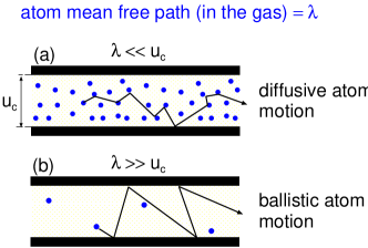
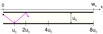
In this paper we study the leakage of air at the nominal contact region between a suction cup and the countersurface (substrate). We will show that for a suction cup to not fail within typical time of use ( year) the surface separation at the most narrow constrictions along the biggest percolating interfacial gas flow (leakage) channels must be below . This is much smaller than the (average) air molecule mean-free-path (due to collisions between the gas molecules), which implies that the gas flow between the collisions with the solid walls is mainly ballistic rather than diffusive (the so called Knudsen limit) (see Fig. 1).
In Sec. 2, 3 and 4 we discuss concepts pertaining to diffusive and ballistic air leakage, and develope a simple theory for suction cups. In Sec. 5 we present experimental results and prediction results of air leakage into the suction cups. We show how the lifetime (time for deatachment) vary with the pull-off force and the surface roughness of counterface. In Sec. 5 we also discuss the effect of suction cup stiffness on its lifetime, along with discussion on influence of water leakage on suction cup lifetimes. In Sec. 6 we propose biomimetic design of a suction cup based on our research findings.
A short version of this paper has been submitted for consideration for publication elsewherearx .
2 Qualitative discussion: diffusive or ballistic air flow?
Consider a suction cup squeezed against a nominally flat surface and exposed to an external normal pulling force . A suction cup detach from the substrate after some time period , which we will refer to as the failure time, due to leakage of air into the suction cup. For most suction cups and practical applications the volume of gas at atmospheric pressure in the suction cup at the point of failure is of order . Here we assume that gas leakage only occur in open (non-contact) channels at the rubber-substrate nominal contact area. For very smooth surfaces the contact area may percolate resulting in no gas leakage, but here we assume some surface roughness and that percolating non-contact channels exist.
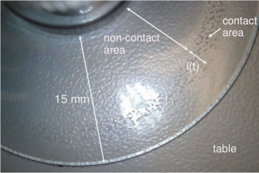
The rubber-substrate contact pressure is largest in a narrow annular region close to the inner contact radius (see Fig. 2). Let be the width of the contact region in the radial (gas-leakage) direction and the length of the contact annulus in the angular direction. Typically . When the surface separation is small enough the gas-leakage is given by the ballistic flow equation and the gas leak-rate (molecules per unit time) is (see Sec. 4.2):
Here is the external (atmospheric) pressure, and the gas pressure inside the suction cup. The separation between the surfaces at the most narrow constrictions along the biggest open channels, the so called critical junctions, is denoted by , and is the thermal energy. The average velocity of an air molecule (at room temperature) is . We approximate (1) with
The volume of gas at atmospheric pressure contain gas molecules where, assuming an ideal gas, . The time it takes for gas molecules to leak into the suction cup is (approximately) determined by . Using (2) this gives
or
Assuming and the failure time we get . In a more realistic case, if a suction cup fail after one year () we get . Here we note that the gas leakage is mainly via the ballistic gas flow (as assumed above) when the gas molecule mean free path (see Sec. 4.3). Since the mean free path of a gas molecule at atmospheric pressure is of order it follows that, even if a suction cup fail after just , the gas molecules in the critical constriction move (mainly) ballistically, rather than diffusively, between the collisions with the solid walls. In some applications below the surface roughness is so large that the suction cup failure time (lifetime) is of order . In these cases the ballistic and diffusively gas transport are roughly equaly likely.
3 Theory
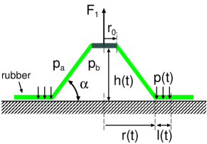
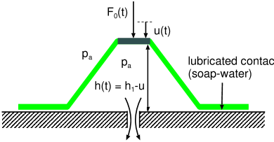
The suction cup we study below can be approximated as a trunkated cone with the diameter . The angle and the upper plate radius are defined in Fig. 3. When a suction cup is pressed in contact with a flat surface the rubber cone will make apparent contact with the substrate in an annular region, but the contact pressure will be largest in a smaller annular region of width formed close to the inner edge of the nominal contact area (see Fig. 2 and 3). We will assume that the rubber-substrate contact pressure in this region of space is constant, , and zero elsewhere.
If we define the volume of gas inside the suction cup is
Since
or
we get
where . The elastic deformation of the rubber film (cone) needed to make contact with the substrate require a normal force , which we will refer to as the cup (non-linear) spring-force. This force result from the bending of the film and to the (in-plane) stretching and compression of the film needed to deform (part of) the conical surface into a flat circular disc or annulus (see Appendix A). We assume that the rubber cup is in repulsive contact with the substrate over a region of width . Since the thickness of the suction cup material decreases as increases, we expect that decreases as increases. From optical pictures of the contact we have found that to a good approximation
where where is the width of the contact region when , and the width of the contact region when . The contact pressure in the circular contact strip is assumed to be constant
where is a number between 0.5 and 1, which depends on how the gas pressure change from for to for .
The function can be easily measured experimentally (see below), or calculated using the FEM method (see also Appendix A). We note that depends on how fast the suction cup is compressed i.e. on the speed . This is due to the viscoelastic nature of the suction cup material as will be discussed further below.
Assume that the pull-force act on the suction cup (see Fig. 3). The sum of and the cup spring-force must equal the force resulting from the pressure difference between outside and inside the suction cup, i.e.
We assume that the air can be treated as an ideal gas so that
The number of molecules per unit time entering the suction cup, , is given by
where
The (square-unit) leak-rate function will be discussed in Sec. 4.
The equations (3)-(9) constitute 7 equations from which the following 7 quantities can be obtained: , , , , , and . The equations (3)-(9) can be easily solved by numerical integration.
The suction cup stiffness force depends on the speed with which the suction cup is compressed (or decompressed). The reason for this is the viscoelastic nature of the suction cup material. To take this effect into account we define the contact time state variable asRuina ; Rice ; Ref1 :
with . For stationary contact, , this equation gives just the time of stationary contact, . When the ratio is non-zero but constant (10) gives
where . Thus for we get , which is the time a particular point on the suction cup surface stay in the rubber-substrate contact region of width . It is only in this part of the rubber-substrate nominal contact region where a strong (repulsive) interaction occur between the rubber film and the substrate, and it is region of space which is most important for the gas sealing process.
From dimensional arguments we expect that is proportional to the effective elastic modulus of the cup material (see below and Appendix A). We have measured at a constant indentation speed , corresponding to a constant radial velocity (see (3)). In this case the effective elastic modulus is determined by the relaxation modulus calculated for the contact time . However, in general may be strongly time-dependent. We can take that into account by replacing the measured by the function .
To calculate the leakrate function we need the relation between the interfacial separation and the contact pressure . For this we have used the Persson contact mechanics theoryBP ; Alm ; uc1 . The relation between and depends on the elastic modulus of the suction cup. However, as pointed out above, the suction cup is made from a viscoelastic material so the effective modulus is time (or frequency) dependent. In the present study we have taken this into account by using the relaxation modulus evaluated at the time given by the contact state variable . This is a good approximation as long as the no slip occur between the rubber and the substrate. When slip occur, depending on the slip velocity and the relevant surface roughness wavenumber , the suction cup material may be exposed to much higher perturbing frequencies than the frequency determined by contact state variable . We will discuss this topic further below.
4 Diffusive and ballistic gas leakage
The gas leakage result from the open (non-contact) channels at the interface between the rubber film and the substrate. Most of the leakage occur in the biggest open flow channels. The most narrow constriction in the biggest open channels are denoted as the critical constrictions. Most of the gas pressure drop occur over the critical constrictions, which therefore determine the leak-rate to a good approximation. The surface separation in the critical constrictions is denoted by . Theory shows that the lateral size of the critical constrictions is much larger than the surface separation (typically by a factor of )seal1 ; seal2 ; seal3 .
In the theory for suction cups enters the leakrate function (see (9)). In this section we show how this function can be calculated when the gas flow through the critical constrictions occur in the diffusive and ballistic limits (see Fig. 1). We also present an interpolation formula which is (approximately) valid independent of the ratio between the gas mean free path and the surface separation at the critical constrictions.
4.1 Diffusive flow
We treat the air as an ideal gas so that the average gas molecule velocity
where is the mass of a gas molecule. The mean free path is the average distance an atom (or molecule) move (on the average) before it makes its first collision with another gas atom. The gas viscosity
where is the gas molecule number density. Note that so that and are independent of the gas number density, and .
If the gas can be treated as a compressible Newtonian fluid we gethydro
Using , and (11) and (12) this gives
4.2 Ballistic flow
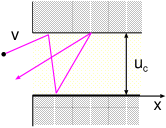
We consider the flow of gas atoms through the critical junction in the ballistic limit . This limit cannot be studied using continuum fluid mechanics (Navier Stokes equations), but require a more atomistic approach, e.g., using the Boltzman equationBoltz1 ; Boltz2 ; Boltz3 . Here we will present a simple argument (Fig. 4 and 5) which basically gives the result as a more accurate treatement.
We approximate the critical constriction with a rectangular junction with height and width and length (in the gas leakage direction) . The flow of atoms into the junction from the high pressure side is times the area of the constriction given by . (The factor of 1/4 is the result of the fact that only half of the atoms moves in the positive -direction, and due to the fact that on the average they only move in the -direction with the speed .) Thus the atom flow into the constriction is . However, the gas atoms will scatter from the walls in a random way (diffusive scattering) due to atomic surface roughness on the walls, and also due to the random thermal motion of the wall atoms. Thus some of the atoms which enter the junction will get back-scattered and return to the high pressure volume (see Fig. 4). It turns out only a fraction of the atoms will be able to penetrate the junction (see Fig. 5). Thus the net number of atoms per unit time, leaving the constriction on the low pressure side after entering the constriction on the high pressure side, will be
Taking into account the counter-flux of atoms (atoms, entering the critical constriction from the low pressure side, from the volume ), this gives
In general, unless we are close to the point where the contact area percolateDapp2 ; martin1 , , and taking into account the geometrical factor we get from (15)
Using the ideal gas law we can also write
4.3 Interpolation formula
We can interpolate between the limits (13) and (17) using
or
where and where we define the average mean free path
The gas leakage equation (19) is in good agreement with more accurate treatements using the Boltzman equation, and with experimentsBoltz1 .
Note that so that if we get . If we get from (19):
We can interpret the factor
as defining an effective mean free path. Using (19) we get
Note that depends on the contact pressure since the critical separation depend on the contact pressure.
5 Experimental results and analysis
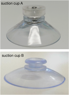
We will present experimental results for the suction cup A shown in Fig. 6. The suction cup is made from soft polyvinyl chloride (soft-PVC) and has a diameter of . We first present results for the topography of the substrate surfaces used in the study. Next we present results for the relaxation modulus of the soft-PVC, and the suction cup stiffness force. Finally we present measurements of the suction cup failure time under different conditions.
5.1 Surface roughness power spectra
The most important information about the surface topography of a rough surface is the surface roughness power spectrum. For a one-dimensional (1D) line scan the power spectrum is given by
where stands for ensemble averaging. For surfaces with isotropic roughness the 2D power spectrum can be obtained directly from as described elsewhere Nyak ; CarbLor . For randomly rough surfaces, all the (ensemble averaged) information about the surface is contained in the power spectrum . For this reason the only information about the surface roughness which enter in contact mechanics theories (with or without adhesion) is the function . Thus, the (ensemble averaged) area of real contact, the interfacial stress distribution and the distribution of interfacial separations, are all determined by BP ; Alm .
Note that moments of the power spectrum determines standard quantities which are output of most stylus instruments and often quoted. Thus, for example, the mean-square (ms) roughness amplitude is given by
Using an engineering stylus instrument we have studied the surface topography of 6 different surfaces used in our suction cup experiments. The topography measurements was performed using Mitutoyo Portable Surface Roughness Measurement Surftest SJ-410 with a diamond tip with the radius of curvature , and with the tip-substrate repulsive force . The scan length and the tip speed .
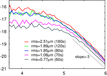
Fig. 7 shows the 1D surface roughness power spectra of 5 sandblasted poly(methyl methacrylate) (PMMA) surfaces. The surfaces was sandblasted under identical conditions but for different time periods resulting in surfaces with different rms roughness values which increases from to as the sandblasting time increases from to .
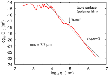
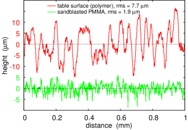
We also used a table surface (the surface shown in Fig. 2). The 1D power spectrum of this surface is shown in Fig. 8. Note the “hump” in the power spectrum centered at (indicated by an arrow in the figure), corresponding to a wavelength of order . The surface structure generating this hump can be easily seen in Fig. 2 and also detected in the measured line scan height profile . Thus, in Fig 9 we show the surface height profiles of the table surface (red) and of a sandblasted PMMA surface (green). The surfaces have the rms roughness amplitudes and , respectively. Note that the table surface have a quasi-periodic structure with a wavelength of order , while the sandblasted surface appears randomly rough.
Using the power spectra shown above we can calculate the height of the critical constrictionAlm ; uc1 ; uc2 . This can be done directly using the critical junction theoryseal3 , or by calculating first the leakrate using the effective medium theoryseal2 and identifying the calculated leakrate with the expected (critical junction) expression involving . Both approaches gives nearly the same result but the second approach was used here as it is expected to be more accurate.
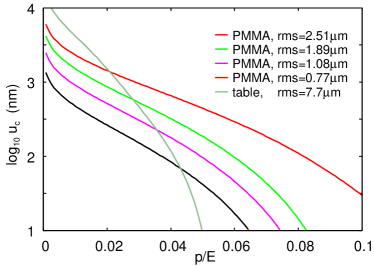
Fig. 10 shows the logarithm of the separation (in nm) at the critical constriction as a function of the applied nominal squeezing pressure divided by the Young’s modulus. The most interesting pressure region is for of order or less than 1 atmosphere, which correspond to of order 0.025 or less (assuming ). For the pressure 1 atmosphere the surface separation at the critical constrictions are 1.17, 0.68, 0.40 and for the sandblasted PMMA with the rms roughness 2.51, 1.89, 1.08 and . For the table surface at the same pressure . We note that for there is about equal probability for ballistic and diffusive gas flow, so clearly in the present cases ballistic flow will contribute in an important way to the gas leakage into the suction cups.
5.2 Viscoelastic relaxation modulus
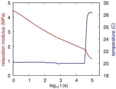
The two suction cups we use (see Fig. 6) are made from a soft-PVC polymer. Using a Q800 DMA instrument produced by TA Instruments, we have studied strain relaxation of the material used for cup A. In Fig. 11 we show the effective Young’s relaxation modulus as a function of time . In the experiments a thin strip (length , cross section area ) of the polymer is loaded with a constant force in elongation mode at time , and the length of the strip is measured as a function of time. From the strain we obtain the effective modulus where . We show results for , where the strain change from to as the time increases from to . Starting at the temperature gradually increased to with resulted in a faster increase in the strain. The effective Young’s relaxation modulus decreases from for to for .
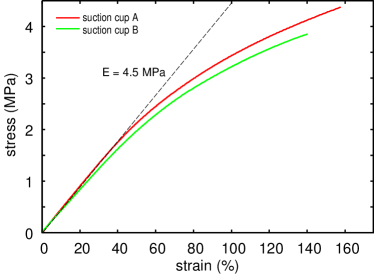
We have also performed strain-sweep and temperature-sweep measurements for both suction cup A and B. The results are presented in Appendix B and shows that the two suction cups are made from soft PVC with nearly the same viscoelastic properties. Furthermore, the stress-strain curve is nearly linear up to about , which is in sharp contrast to rubber materials with filler which exhibit strongly non-linear properties already for the strain due to the break-up of the filler networklubricant .
5.3 Suction cup stiffness force
We have measured the relation between the normal force and the normal displacement of the (rigid) top plate of a suction cup. In the experiments we increase the displacement of the top plate at a constant speed and measure the resulting force. If denote the normal displacement, where correspond to just before contact (undeform suction cup and ), then the height of the deformed suction cup , where is the height of the undeformed suction cup (see Fig. 12).
For the stiffness measurements we have used an instrument produced by SAUTER GmbH (Albstadt, Germany). The displacement can be changed with a resolution of 0.01 mm while the force sensor can measure forces up to 500 N with an accuracy of 0.1 N.
We have measured the relation for 3 different cases were the suction cup was squeezed against (a) a glass plate lubricated by soap water, (b) a dry clean glass plate and (c) a dry clean sandblasted glass plate. For case (a) and (b) we also performed measurements when there was a hole in the in the glass plate (see Fig. 12); this allowed the air to leave the suction cup without any change in the pressure inside the suction cup (i.e. is equal to the atmospheric pressure).
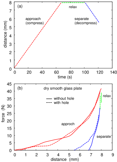
Fig. 13 (b) shows the interaction force (in N) acting on a suction cup as a function of the displacement (in mm). The suction cup is squeezed against a smooth dry glass plate without (solid line) and with (dashed line) a hole in the center through which the air can leave so the air pressure inside the rubber suction cup is the same as outside (atmospheric pressure). The indentation cycle [see Fig. 13(a)] consisting of squeezing (approach speed ), relaxation ( for ) and retraction (separation or pull-off speed ). Note that during separation the suction cup pushed against the glass plate with the hole is able to retract farther than the suction cup pushed against the glass plate without a hole. This is due to the fact that in the latter case (partial) vacuum exist inside the suction cup and the top of the suction cup stop to retract when the spring force equal the vacuum force.
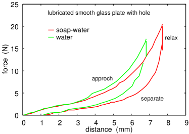
The result in Fig. 13(b) is influenced by the adhesion and friction between the suction cup and the glass plate. This is the reason for why even for the glass plate with a hole the retraction stops for . However, the adhesion and friction can be removed (or strongly reduced) if the glass surface is lubricated. This is illustrated in Fig. 14 which shows the interaction force as a function of the distance for the case of a smooth glass plate (with a hole in the center) lubricated with water (green) and soap-water (red). In these cases during retraction when the distance i.e., the top of the suction cup has nearly returned to its original position. The small displacement remaining (1 mm) may be attributed to viscoelastic relaxation of the suction cup PVC material.
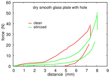
Adhesion and friction can also be reduced by coating the glass surface with an inert monolayer film. This is illustrated in Fig. 15 which shows the curve for clean dry glass (red) and silanized glass (green). Note that for the silanized glass the curve is very similar to the case of the lubricated glass surface.
5.4 Gas and water leakage
We have studied how the failure time of a suction cup depends on the pull-off force (vertical load) and the substrate surface roughness. We have also studied the influence on the failure time of a fluid (water) film at the rubber-substrate interface. For the dry contact the suction cup was always attached to the lower side of a horizontal surface and a mass-load was attached to the suction cup. We varied the mass-load from 0.25 kg to 8 kg. If full vacuum would prevail inside the suction cup, the maximum possible pull-off force would be . Using and we get or about 11 kg mass load. However, the maximum load possible in our experiments for a smooth substrate surface is about 9 kg, indicating that no complete vacuum was obtained. This may, in least in part, be due to problems to fully remove the air inside the suction cup in the initial state. In addition we have found that for mass loads above the pull-off is very sensitive to instabilities in the macroscopic deformations of the suction cup, probably resulting from small deviations away from the vertical direction of the applied loading force.
Below we will compare the experimental results to the theory predictions. In the theory enter a few (mainly geometrical) parameters defined in Sec. 3, which we have determined from simple measurements (see Table 1).
| quantity | cup A | cup B |
|---|---|---|
The dependency of the failure time on the pull-off force
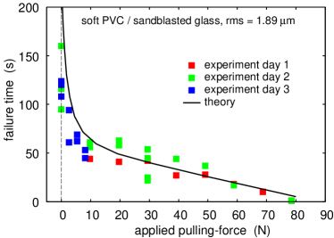
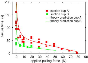
Fig. 17 shows the dependency of the pull-off time (failure time) on the applied pulling force. The results are for the soft PVC suction cup in contact with a sandblasted PMMA surface with the rms-roughness . Before the measurement, both surfaces was cleaned with soap water. The different colors of the square symbols correspond to data obtained at different days. The solid line is the theory predictions, using as input the surface roughness power spectrum of the PMMA surface, and the measured stiffness of the suction cup, the latter corrected for viscoelastic time-relaxation as described in Sec. 3. Note the good agreement between the theory and the experiments in spite of the simple nature of the theory.
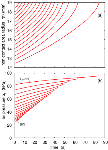
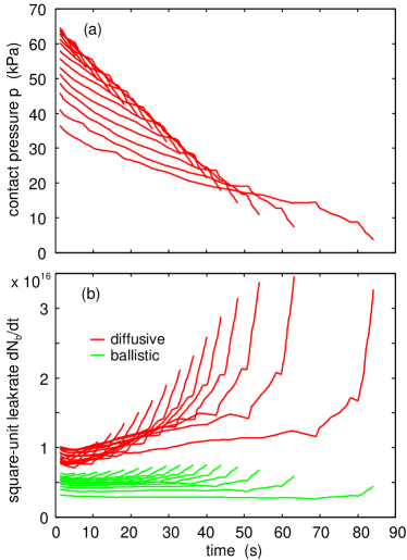
Fig. 18(a) shows the calculated time dependency of the radius of the non-contact region, and (b) the pressure in the suction cup. We show results for several pull-off forces from in steps of to . Fig. 19(a) shows similar results for the contact pressure and (b) for the square-unit gas leakage rate (molecules per unit time). The noise in the curves reflect the noise in the measured stiffness and relaxation modulus curves which was used with linear interpolation, but without smoothing, in the calculations. In the present case the air flow is mainly diffusively but for smoother surfaces the ballistic air flow dominate.
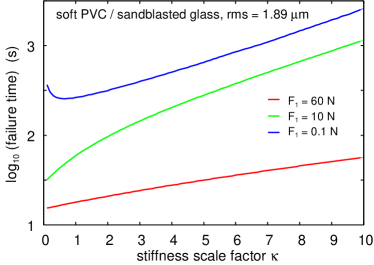
Finally, we study the influence of the suction cup stiffness on the lifetime. Fig. 20 shows the calculated stiffness dependency of the logarithm of the suction cup lifetime. The results are for the same system as in Fig. 17 but we have scaled the stiffness force by a factor . That is, we have replaced with , but all other parameters are the same as in Fig. 17. We show results for the applied pull-off force (blue), (green) and (blue). Note that increasing the magnitude of by a scaling factor result in a monotonic increase in the lifetime of the suction cup with increasing , except for very low applied pulling forces where the lifetime first drop with increasing . The reason for the increase in the lifetime with increasing stiffness is the increase in the contact pressure , and hence reduction in the surface separation at the critical constrictions, with increasing stiffness.
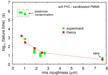
The dependency of the failure time on the surface roughness
Fig. 21 shows the dependency of the pull-off time (failure time) on the substrate surface roughness. The results are for the type A soft PVC suction cups in contact with sandblasted PMMA surfaces with different rms roughness, and a table surface. All surfaces were cleaned with soap water before the experiments and a new suction cup was used for each experiment. Note that for “large” roughness the predicted failure time is in good agreement with the measured data, but for rms roughness below the measured failure times are much larger than the theory prediction. In addition, the dependency of the radius of the non-contact region on time is very different in the two cases: For roughness larger than the radius increases continuously with time as also expected from theory (see Fig. 18(a)). For roughness below the boundary line stopped to move a short time after applying the pull-off force, and remained fixed until the detachment occurred by a rapid increase in (catastrophic event). We attribute this discrepancy between theory and experiments to transfer of plasticizer from the soft PVC to the PVC-PMMA interface; this (high viscosity) fluid will fill-up the critical constrictions and hence stop, or strongly reduce, the flow of air into the suction cup. This proposal is consistent with many studies of soft PVC which shows relative fast migration of the plasticizer to the PVC surface. Thus, if is the diffusivity of a plasticizer molecule and the volume fraction of the plasticizer in the PVC, then we expect that after time a layer of plasticizer of thickness has diffused to the PVC-PMMA interface. The diffusivity depend on the type of plasticizer used, but at room temperature is typically in the rangeplast1 . Assuming and we get . However, the concentrating of plasticizer may be reduced in the surface region and in this case the transfer rate would be reduced. This is consistent with many studiesplast2 of the transfer of plasticizer from soft PVC to various contacting materials. These studies show typical transfer rates (at room temperature) correspond to a thick film of plasticizer after one week waiting time. Additional support for the hypothesis that mobile molecules from the PVC block the critical constrictions is the following observation:
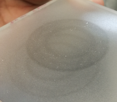
Fig. 22 shows the footprint from a soft PVC suction cup which detached after days of contact with a sandblasted PMMA surface with the rms roughness . In the experiment the suction cup was first squeezed into contact with the PMMA surface. Next a pull-off force (vertical load) was applied, resulting in the radius increasing almost instantaneously (in ) to , which is determined by the condition that the gas pressure force equal the pull-off force plus the spring force. At this point the boundary line stopped to move, and remained fixed (at ) until the detachment occurred by a rapid (within ) increase in from to .
The suction cup and the PMMA surface used in Fig. 22 was originally cleaned with soap water. However, Fig. 22 shows that mobile molecules, probably the PVC plasticizer, have diffused from inside the PVC to the interface where it tend to fill-out the surface roughness cavities, resulting in an effective smoother surface which scatter the light less than the uncovered surface. We also observed that small dust particles tended to accumulate on the contaminated surface area, indicating that the contamination film is more sticky than the clean PMMA surface.
The darkest (i.e. most contaminated) region in Fig. 22 is the annular strip of width where the contact pressure is highest during this waiting time period for . This is due to the high contact pressure in the region , which increases the transfer of the plastisizer to the PMMA surface as compared to the contact region , where the contact pressure is much smaller. This pressure-induced increase in the transfer of fluid (or mobile molecules) from a solid to the surface of a counter material is well known in the context of soft-PVC, and also know for other fluid filled materials, e.g., the cartilage of the human jointsjoint1 ; joint2 ; joint3 .
Fig. 22 shows two suction cup footprints. The weaker one resulted from an experiment performed several weeks earlier. This footprint is weaker than that of the last measurement because of evaporation of the contamination molecules, and due to the cleaning with soap water performed before the second measurement.
Influence of a water film on the failure time
We have performed two experiments involving water. In the first experiment the substrate is covered by a thick water layer (about 1 cm thick), and in the second experiment we just added a few drops of water at the rim of the contact between the suction cup and the substrate, after they had been squeezed together in the dry state. In these experiments the suction cup was squeezed against the horizontal substrate from above, and a pulling force was applied to the suction cup.
When a thick fluid film occur on the surface the suction cup failure time is much longer than in the dry state. Assuming that the water can be treated as an incompressible Newtonian fluid, and assuming laminar flow, the volume of fluid flowing per unit time into the suction cup is given by
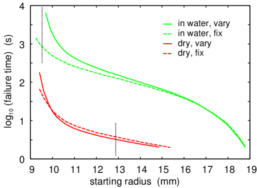
The much higher viscosity of water than of air ( for water as compared to of air), result in a longer failure time in water than in air. We have also found that in water the pull-off force is very sensitive to the applied squeezing force used in preparing the initial state. This is consistent with the theory. Thus, Fig. 23 shows calculated results (for the table surface) for the dependency of the pull-off time (failure time) on the initial non-contact radius (for the pull-off force ), , in the dry state (red) and in water (green). Note that depends on the force with which the suction cup was squeezed into contact with the counter surface (which determines the amount of trapped gas or water in the suction cup in the initial state).
The vertical dotted lines in Fig. 23 indicate typical initial contact radius values for the dry case and in water. Assuming the water can be treated as an incompressible fluid, the initial radius of the contact is smaller in water than in the dry state. However, the low pressure in the trapped water can result in cavitation; this process depends on time and the amount of gas dissolved in the water, which makes the contact in water more complex than in the air. Visual inspection of suction cups squeezed against a smooth glass plate in water always show some trapped gas (and water) inside the suction cup. Nevertheless, the initial radius of the non-contact region is smaller when the contact is formed in water than if it is formed in the dry state.
The suction cup lifetime observed in water depends sensibly on relative small variations in the initial non-contact radius (resulting from fluctuations in the force used in squeezing the suction cup in contact with the table surface). Thus, under nominally identical conditions in water the lifetime varied in the range . (Note: in all the experiments the suction cups were squeezed into contact with the substrate by a human hand, and some variations in the applied force cannot be avoided.) Similar experiments for dry conditions gives much smaller variations in the lifetime, which vary in the range . This is consistent with Fig. 23.
In Fig. 23 the solid lines use the relaxation modulus (evaluated for the time given by the state variable ) when calculating the interfacial separation at the critical constriction. Using the relaxation modulus for calculating the time-dependency of the spring force (via the state variable ) is a valid procedure, but if slip occur at the rubber-substrate interface then the same procedure may not be accurate for the interfacial separation. Thus, the interfacial separation depends on the deformation frequencies the rubber is exposed to during slip between the suction cup and the counter surface. These frequencies depends on the slip velocity and on the wavelength (or wavenumber ) of the relevant surface roughness components: . The most important roughness are the components with wavenumber smaller than the the wavenumber determined by the magnification where the first non-contact percolating flow channel can be observed (see Ref. seal3 ). Using the rubber friction theory developed elsewhereBP , it is possible to take into account the dependency of the interfacial separation on the sliding speed, but for the low slip velocities involved in most of the present applications (typically of order ) the perturbing frequencies are low (of order ), and we expect only small modifications of the results presented above. To illustrate this, the dashed lines in Fig. 23 use the effective modulus () corresponding to contact time (corresponding to the frequency ).
In the second experiment involving water the suction cup was first squeezed against the substrate in the dry state, after which a few water drops was added at the contact rim. In this case we observed very violent flow processes (as in boiling of water), where non-periodic, pulsating flow of water-air mixtures occurred in the open (non-contact) interfacial channels. In Ref. movie we show a movie illustrating how mixtures of water and air is pulled into the suction cup via the (non-contact) leakage channels at the rubber-substrate interface.
5.5 Results for another suction cup
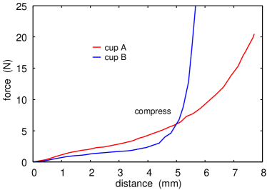
We have performed a few experiments for a second type of suction cup denoted by B (see Fig. 6). The suction cups A and B are both made from soft PVC (see Appendix B) and both have the diameter . However, for suction cup B the angle in contrast to for suction cup A. In addition, the thickness of the PVC film of suction cup A is larger than for cup B. For both cups the thickness decreased nearly linarly with the distance from the center of the suction cup (from at to at for cup A and from at to at for cup B). This difference in the thickness variation influence the suction cup stiffness force as shown in Fig. 24. Note that before the strong increase in the curve which result when the suction cup is squeezed into complete contact with the counter surface (and is due to compression of the suction cup material) the suction cup A has a stiffness nearly twice as high as that of the suction cup B. Note that the fact that the angle is smaller for the cup B than for the cup A is the reason for why a smaller displacement is needed in order to reach the point where the stiffness force abruptly increases (where the suction cup is in complete contact with the substrate), see Fig. 24.
The smaller angle for suction cup B than for cup A imply that if the same amount of gas would leak into the suction cups the gas pressure inside the suction cup will be highest for the suction cup B. This will tend to reduce the lifetime of cup B. Similarly, the smaller stiffness of the cup B result in smaller contact pressure , which will increase the leakage rate and reduce the lifetime (see Fig. 20). Hence both effects will make the lifetime of the suction cup B smaller than that of the cup A.
In Fig. 25 we show the dependency of the pull-off time (failure time) on the applied (pulling) force for suction cup B for the sandblasted PMMA surface with the rms roughness (green squares and line). We also show the results for suction cup A (red) (from Fig. 17). In the calculations we have used the parameters shown in table 1. As expected, the lifetime of the suction cup B is less than that of suction cup A.
6 Discussion
Many animals have developed suction cups to adhere to different surfaces, e.g., the octopusSmith ; Gorb1 ; Gorb2 ; Benne or northern clingfishGorb3 . Studies have shown that these animals can adhere to much rougher surfaces then man-made suction cups. This is due to the very low elastic modulus of the material covering the suction cup surfaces. Thus, while most man-made suction cups are made from rubber-like materials with a Young’s modulus of order a few MPa, the suction cups of the octopus and the northern clingfish are covered by very soft materials with an effective modulus of order .
When a block of a very soft material is squeezed against a counter surface in water it tends to trap islands of water which reduces the contact area and the frictionMug1 ; Mug2 ; Mug3 . For this reason the surfaces of the soft adhesive discs in the octopus and the northern clingfish have channels which allow the water to get removed faster during the approach of the suction cup to the counter surface. However, due to the low elastic modulus of the suction cup material, the channels are “flattened-out” when the suction cup is in adhesive contact with the counter surface, and negligible fluid leakage is expected to result from these surface structures.
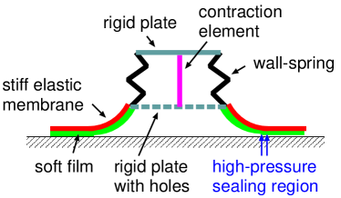
There are two ways to attach a suction cup to a counter surface. Either a squeezing force is applied, or a pump must be used to lower the fluid (gas or liquid) pressure inside the suction cup. The latter is used in some engineering applications. However, it is not always easy for the octopus to apply a large normal force when attaching a suction cup to a counter surface, in particular before any arm is attached, and when the animal cannot wind the arm around the counter surface as may be the case in some accounts with sperm whale. Similarly, the northern clingfish cannot apply a large normal force to squeeze the adhesive disk in contact with a counter surface. So how can they attach the suction cups? We believe it may be due to changes in the suction cup volume involving muscle contraction as illustrated in the octopus inspired suction cup shown in Fig. 26.
The suction cup in Fig. 26 consist of a soft material (green), e.g., double network hydrogelGong , covered by elastically stiff membrane (red) in order to increase the contact stiffness, and hence the contact pressure in the sealing region. Without the contraction filament (pink) the suction cup must be squeezed in contact with the counter surface. With the contraction filament, the suction cup body (black) can be compressed before contact with the substrate. After contact with the substrate the compression filament is relaxed resulting in an elongation of the suction cup body and fluid flow into the cup body via the holes in the bottom plate. This result in a reduction in the water pressure inside the suction cup. As a result, the suction cup will be compressed against the substrate.
For adhesion to very rough surfaces, the part of the suction cup in contact with the substrate must be made from an elastically very soft material. However, using a very soft material everywhere result in a very small suction cup stiffness. We have shown (see Fig. 20) that a long lifetime require a large enough suction cup stiffness. Only in this case will the contact pressure be large enough to reduce the water leakrate to small enough values. For this reason we suggest that the soft material (green) is bound to a stiffer material (red) as indicated in Fig. 26. The thickness of the green layer must be at least of order the longest wavelength of the important surface roughness on the counter surface in order to be able to deform at the interface and make nearly complete contact with the counter surface.
For suction cups used in the air the lowest possible pressure inside the suction cup is , corresponding to perfect vacuum. In reality it is usually much larger, . For suction cups in water the pressure inside the suction cup could be negative where the liquid is under mechanical tension. This state is only metastable, but pressures as low as has been observed for short timesCav . For water in equilibrium with the normal atmosphere one expect cavitation to occur for any pressure below the atmospheric pressure, but the nucleation of cavitives may take long time, and depends strongly on impurities and imperfections. For example, crack-like surface defects in hydrophobic materials may trap small (micrometer or nanometer) air bubbles which could expand to macroscopic size when the pressure is reduced below the atmospheric pressure.
Negative pressures have been observed inside the suction cups of octopus. Thus, in one studySmith1 it was found that most suction cups have pressures above zero, but some suction cups showed pressures as low as .
Trapped air bubbles could influence the water flow into the suction cup by blocking flow channels. For not degassed water, whenever the fluid pressure falls below the atmospheric pressure cavitation can occur, and gas bubbles could form in the flow channels and block the fluid flow due to the Laplace pressure effect. For the suction cups studied above, in the initial state the Laplace pressure is likely to be smaller than the fluid pressure difference between inside and outside the suction cup, in which case the gas bubbles would get removed, but at a later stage in the detachment process this may no longer be true. This is similar to observations in earlier model studies of the water leakage of rubber seals, where strongly reduced leakage rates was observed for hydrophobic surfaces when the water pressure difference between inside and outside the seal become small enoughseal4 .
7 Summary and conclusion
We have studied the leakage of suction cups both experimentally and using a multiscale contact mechanics theory. In order to describe the air leakage through the contact between a suction cup and randomly rough counterface, a theory was developed which describes the air flow in both the diffusive limit () and ballistic limit (), where is the interfacial separation at the critical constriction. In the experiments suction cups (made of soft PVC) was pressed against sandblasted PMMA sheets. We found the failure times of suction cups to be in good agreement with the theory, except for surfaces with rms-roughness below , where diffusion of plasticizer from the PVC to the PMMA counterface resulting in blocking of critical contrictions. The study shows that the the suction cup volume and suction cup stiffness are important design parameters, but most important is the elastic modulus of the suction cup material; a low modulus can drastically help in reducing gas (or liquid) leakage. We have suggested an improved biomimetic design of suction cups, inspired by octopus vulgaris, which could show improved failure time under water and on surfaces with varying degree of surface roughness.
Appendix A: Estimation of the stiffness force
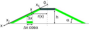
We will estimate the stiffness force assuming there is no-slip at the rubber-substrate interface. The no slip assumption holds approximately for the suction cup in contact with the smooth clean glass plate with a hole. The elastic energy stored in the suction cup when it is pressed against the substrate is assumed to be given by the work nexcessary to compress the suction cup in the radial direction so that each radial segment of length is projected vertically upon the flat substrate surface and result in a segment of length (see Fig. 27). The radial strain in the compressed segment is
The elastic energy
where is Young’s modulus and the volume of deformed material. If we have squeezed the region from to into contact with the substrate the volume
where is the thickness of the suction cup at the radial location . If we assume , where and we get
To calculate the normal force (in response to the normal displacement ) we use that
Since
we get
and
As an example, assume so that and we get
Using that this gives
For small indentation this gives a stiffness force which increase linearly with . Using , and (cup A) and measuring in mm this eqation gives which is in good agreement with the measured stiffness for dry contact (see Fig. 13) for up to a few about (note for ). For above the compression of the rubber will start to contribute to , and will increase more rapidly with then predicted by the theory above.
Appendix B: Viscoelastic modulus of the soft PVC
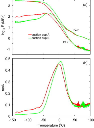
We have measured the viscoelastic modulus of the soft PVC of the suction cups A and B. The measurements where performed in oscillatory tension mode using a Q800 DMA instrument produced by TA Instruments. Fig. 28 shows (a) the temperature dependency of the low strain () modulus , and (b) , for the frequency . Results are shown for the soft PVC of suction cup A (red) and B (green). Note that both materials exhibit very similar viscoelastic modulus. If we define the glass transition temperature as the temperature where is maximal (for the frequency ) then .
We have also performed measurements where the strain is increased slowly from zero to . Fig. 29 shows the dependency of the stress on the strain for the soft PVC used for the suction cup A (red) and B (green). The strain was increased from zero to its final value in about giving a strain rate of about . The low strain modulus is about for both PVC compounds.
References
- (1) B.N.J. Persson, Sliding Friction: Physical Principles and Applications, Springer, Heidelberg (2000).
- (2) E. Gnecco and E. Meyer, Elements of Friction Theory and Nanotribology, Cambridge University Press (2015).
- (3) J.N. Israelachvili, Intermolecular and Surface Forces, (Academic, London), 3rd Ed. (2011).
- (4) J.R. Barber, Contact Mechanics (Solid Mechanics and Its Applications), Springer (2018).
- (5) B.N.J. Persson, Contact mechanics for randomly rough surfaces, Surface Science Reports 61, 201 (2006).
- (6) B.N.J. Persson, O. Albohr, U. Tartaglino, A.I. Volokitin and E. Tosatti, On the nature of surface roughness with application to contact mechanics, sealing, rubber friction and adhesion, J. Phys.: Condens. Matter 17, R1 (2005)
- (7) C. Creton, M. Ciccotti Fracture and adhesion of soft materials: a review Reports on Progress in Physics 79, 046601 (2016).
- (8) R Spolenak, S Gorb, H Gao, E Arzt, Effects of contact shape on the scaling of biological attachments, Proceedings of the Royal Society A: Mathematical, Physical and Engineering Sciences 461, 305 (2005).
- (9) L. Pastewka, M.O. Robbins Contact between rough surfaces and a criterion for macroscopic adhesion, Proceedings of the National Academy of Sciences 111, 3298 (2014).
- (10) Martin H Müser, Wolf B Dapp, Romain Bugnicourt, Philippe Sainsot, Nicolas Lesaffre, Ton A Lubrecht, Bo NJ Persson, Kathryn Harris, Alexander Bennett, Kyle Schulze, Sean Rohde, Peter Ifju, W Gregory Sawyer, Thomas Angelini, Hossein Ashtari Esfahani, Mahmoud Kadkhodaei, Saleh Akbarzadeh, Jiunn-Jong Wu, Georg Vorlaufer, Andras Vernes, Soheil Solhjoo, Antonis I Vakis, Robert L Jackson, Yang Xu, Jeffrey Streator, Amir Rostami, Daniele Dini, Simon Medina, Giuseppe Carbone, Francesco Bottiglione, Luciano Afferrante, Joseph Monti, Lars Pastewka, Mark O Robbins, James A Greenwood, Meeting the contact-mechanics challenge, Tribology Letters 65, 118 (2017).
- (11) AI Vakis, VA Yastrebov, J Scheibert, C Minfray, L Nicola, D Dini, A Almqvist, M Paggi, S Lee, G Limbert, JF Molinari, G Anciaux, R Aghababaei, S Echeverri Restrepo, A Papangelo, A Cammarata, P Nicolini, C Putignano, G Carbone, M Ciavarella, S Stupkiewicz, J Lengiewicz, G Costagliola, F Bosia, R Guarino, NM Pugno, MH Müser, Modeling and simulation in tribology across scales: An overview, Tribology International (TRIBINT-D-17-01694 - Accepted Manuscript).
- (12) A. Tiwari, Adhesion, Friction and Leakage in Contacts with Elastomers, PhD thesis, Publisher: NTNU (2018).
- (13) BNJ Persson Theory of rubber friction and contact mechanics, The Journal of Chemical Physics 115, 3840 (2001)
- (14) B.N.J. Persson, C. Yang, Theory of the leak-rate of seals, J. Phys.: Condens. Matter 20, 315011 (2008)
- (15) B. Lorenz and B. N. J. Persson, Leak rate of seals: Comparison of theory with experiment, EPL(Europhysics Letters),86, 44006 (2009)
- (16) B. Lorenz, B.N.J. Persson, On the dependence of the leak rate of seals on the skewness of the surface height probability distribution Europhysics Letters 90, 38002 (2010).
- (17) B. Lorenz, B.N.J. Persson Leak rate of seals: Effective-medium theory and comparison with experiment The European Physical Journal E 31, 159 (2010).
- (18) A. Tiwari, L. Dorogin, M. Tahir, K.W. Stöckelhuber, G. Heinrich, N. Espallargas, B.N.J. Persson, Rubber contact mechanics: adhesion, friction and leakage of seals, Soft Matter 13, 9103 (2017).
- (19) W.B. Dapp, A. Lücke, B.N.J. Persson, and M.H. Müser Self-Affine Elastic Contacts: Percolation and Leakage Phys. Rev. Lett. 108, 244301 (2012).
- (20) F.Bottiglione, G. Carbone, L. Mangialardi, G. Mantriota, Leakage mechanism in flat seals, Journal of Applied Physics 106, 104902 (2009)
- (21) W. B. Dapp, M. H. Müser, Fluid leakage near the percolation threshold, Scientific Reports,6, 19513 (2016)
- (22) B.D. Wolf and M.H. Müser, Contact mechanics of and Reynolds flow through saddle points, EPL 109, 44001 (2015).
- (23) A. Tiwari and B.N.J. Persson, Physics of suction cups, Subm. to PRL. See also: arXiv:1905.09042v1 [cond-mat.soft] 22 May 2019.
- (24) A.L. Ruina, Slip instability and state variable friction laws, J. Geophys. res. 88, 10359 (1983).
- (25) J.R. Rice and A.L. Ruina, Stability of steady frictional slipping, J. Appl. Mech. 50, 343 (1983).
- (26) See, e.g., Appendix A in: B. Lorenz, N. Rodriguez, P. Mangiagalli, B.N.J. Persson, Role of hydrophobicity on interfacial fluid flow: Theory and some applications, The European Physical Journal E 37, 57 (2014).
- (27) M.H. Nacer, Tangential Momentum Accomodation Coefficient in Microchannels with Different Surface Materials, PhD thesis, Marseille (2012).
- (28) A.E. Beylich, Solving the kinetic equation for all Knudsen numbers, Physics of Fluids 12, 444 (2000)
- (29) M.H. Nacer, I. Graur and P. Perrier, Mass flow measurement through rectangular microchannel from hydrodynamic to near free molecular regimes, La Houille Blanche, 4, 2011, p. 49-54.
- (30) P.R. Nayak, Random Process Model of Rough Surfaces, J. Lubrication Technol. 93, 398 (1971).
- (31) G. Carbone, B. Lorenz, B.N.J. Persson, A. Wohlers Contact mechanics and rubber friction for randomly rough surfaces with anisotropic statistical properties, The European Physical Journal E29, 275 (2009).
- (32) A. Almqvist, C. Campan, N. Prodanov and B.N.J. Persson, Interfacial separation between elastic solids with randomly rough surfaces: Comparison between theory and numerical techniques, Journal of the Mechanics and Physics of Solids 59, 2355 (2011).
- (33) T.V. Tolpekina, W. Pyckhout-Hintzen, B.N.J. Persson, Linear and Nonlinear Viscoelastic Modulus of Rubber, Lubricants 7, 22 (2019).
- (34) C. Yang, B.N.J. Persson, Contact mechanics: contact area and interfacial separation from small contact to full contact, J. Phys.: Condens. Matter 20, 215214 (2008)
- (35) L. Afferrante, F. Bottiglione, C. Putignano, B.N.J. Persson, G. Carbone, Elastic contact mechanics of randomly rough surfaces: an assessment of advanced asperity models and Persson’s theory, Tribology Letters 66, 75 (2018).
- (36) H. Takehisa, E. Naoko, S. Masahiko, T. Katsuhide, O. Moriyuki, S. Keizoh, T. Mutsuko, K. Kenji, N. Shinichiro, O. Toshio, Release behavior of diethylhexyl phthalate from the polyvinyl-chloride tubing used for intravenous administration and the plasticized PVC membrane, International Journal of Pharmaceutics 297, 30 (2005).
- (37) Jung Hwan Kim, Seong Hun Kim, Chang Hyung Lee, Jae-Woon Nah, and Airan Hahn DEHP Migration Behavior from Excessively Plasticized PVC Sheets, Bull. Korean Chem. Soc. 24, 345 (2003).
- (38) P.R. Lewis, C.W. McCutchen, Experimental evidence for weeping lubrication in mammalian joints, Nature 184, 1285 (1959).
- (39) B.N.J. Persson, M. Scaraggi, Some Comments on Hydrogel and Cartilage Contact Mechanics and Friction, Tribology Letters 23, 66 (2018).
- (40) B.N.J. Persson, A. Kovalev, S.N. Gorb, Simple contact mechanics model of the vertebrate cartilage, Soft Matter 13, 6349 (2017).
- (41) A.M. Smith, Negative pressure generated by octopus suckers: a study of the tensile strength of water in nature, J. exp. Biol. 157, 257 (1991).
- (42) F. Tramacere, E. Appel, B. Mazzolai, S.N. Gorb, Hairy suckers: the surface microstructure and its possible functional significance in the Octopus vulgaris sucker Beilstein journal of nanotechnology 5, 561 (2014).
- (43) K.K. Green, A. Kovalev, E.I. Svensson, S.N. Gorb, Male clasping ability, female polymorphism and sexual conflict: fine-scale elytral morphology as a sexually antagonistic adaptation in female diving beetles, Journal of the Royal Society Interface 10, 20130409 (2013).
- (44) V. Tinnemann, L. Hernandez, S.C.L. Fischer, E. Arzt, R. Bennewitz and R. Hensel, Adhesion: In Situ Observation Reveals Local Detachment Mechanisms and Suction Effects in Micropatterned Adhesives Adv. Funct. Mater. 14, 1807713 (2019)
- (45) D.K. Wainwright, T. Kleinteich, A. Kleinteich, S.N. Gorb, A.P. Summers, Stick tight: suction adhesion on irregular surfaces in the northern clingfish, Biology letters 9, 20130234 (2013).
- (46) B.N.J. Persson and F. Mugele, Squeeze-out and wear: fundamental principles and applications, Journal of Physics: Condensed Matter 16, R295 (2004).
- (47) A.D. Roberts, The Physics of Tire Friction: Theory and Experiment, ed D F Hays and A L Browne(New York: Plenum) (1974)
- (48) A.D. Roberts, D. Tabor Proc. R. Soc. A 325, 323 (1971).
- (49) M. A. Haque, T. Kurokawa, J.P. Gong, Super tough double network hydrogels and their application as biomaterials, Polymer 53, 1805 (2012).
- (50) W.M. Kier, A.M. Smith, The structure and adhesive mechanism of octopus suckers, Integr. Comp. Biol. 42, 1146 (2002).
- (51) https://www.youtube.com/watch?v=4mb76lOqRdc
- (52) E. Herbert, S. Balibar, F. Caupin, Cavitation pressure in water, Phys. Rev. E 74, 041603 (2006).