Nonlinear polaritons in monolayer semiconductor coupled to optical bound states in the continuum
Abstract
Optical bound states in the continuum (BICs) provide a way to engineer very narrow resonances in photonic crystals Marinica2008 ; Hsu2016 ; Lee2012 ; Jin2018 . The extended interaction time in such systems is particularly promising for enhancement of nonlinear optical processes Krasikov2018 ; Bulgakov2019 and development of the next generation of active optical devices Walker2015 ; Sich2016 . However, the achievable interaction strength is limited by the purely photonic character of optical BICs. Here, we mix optical BIC in a photonic crystal slab with excitons in atomically thin semiconductor MoSe2 to form nonlinear exciton-polaritons with a Rabi splitting of 27 meV, exhibiting large interaction-induced spectral blueshifts. The asymptotic BIC-like suppression of polariton radiation into far-field towards the BIC wavevector, in combination with effective reduction of excitonic disorder through motional narrowing, results in small polariton linewidths below 3 meV. Together with strongly wavevector-dependent Q-factor, this provides for enhancement and control of polariton–polariton interactions and resulting nonlinear optical effects, paving the way towards tunable BIC-based polaritonic devices for sensing, lasing, and nonlinear optics.
Optical bound states in the continuum (BICs), supported by photonic crystal structures of certain geometries, have received much attention recently as a novel approach to generating extremely spectrally narrow resonant responses Marinica2008 ; Hsu2016 . Since BICs are uncoupled from the radiation continuum through symmetry protection Lee2012 or resonance trapping Kodigala2017 , they can be robust to perturbations of photonic crystal geometric parameters Jin2018 . This enables a broad range of practical applications, including recently demonstrated spectral filtering Foley2014 , chemical and biological sensing Romano2018a ; Romano2018b , and lasing Kodigala2017 .
Providing an efficient light-trapping mechanism, optical BICs are particularly attractive for enhancing nonlinear optical effects, with recent theoretical proposals discussing enhanced bistability Bulgakov2019 and Kerr-type focusing nonlinearity Krasikov2018 . However, for practical realization of these proposals, a significantly stronger material nonlinear susceptibility is needed than generally available in dielectric-based photonic crystals.
An attractive approach to the enhancement of effective nonlinearity is through the use of exciton-polaritons – hybrid quasi-particles that inherit both the coherent properties of photonic modes and interaction strength of excitons Khitrova1999 ; Walker2015 ; Sich2016 . Hybrid nanophotonic systems incorporating atomically thin transition metal dichalcogenides (TMDs) have emerged as a particularly promising platform owing to their ease of fabrication and possibility of room temperature operation Dufferwiel2015 ; Liu2015 ; Lundt2016 . In addition to conventional microcavity-based designs, TMD exciton-polaritons have been observed in plasmonic lattices Dibos2019 , photonic crystal slabs Zhang2018 ; Gogna2019 , and other nanophotonic structures Barachati2018 .
Coupling TMD excitons to optical BICs in photonic crystals thus will not only boost the potentially achievable nonlinearities but also provide control on the resonant BIC properties through the excitonic fraction in the polariton, as has been proposed theoretically Koshelev2018 .
Here we experimentally demonstrate and investigate nonlinear polaritons formed via strong coupling of excitons in monolayer MoSe2 and optical BIC in a 1D photonic crystal slab, with Rabi splitting of meV and BIC-like radiation suppression in the surface-normal direction. Despite the large meV inhomogeneous broadening of the MoSe2 excitonic line, we achieve small polariton linewidth below 3 meV, corresponding to very well resolved splitting-to-linewidth ratio of and Q-factors up to 900. Using the strongly wavevector-dependent Q-factor of the photonic crystal dispersion, we show controllable reduction in polariton linewidth by a factor of 5-10 when approaching the BIC. The narrow polariton lines allow us to accurately measure polariton–polariton interaction strength through power-dependent spectral blueshifts in resonant reflectance experiment, corresponding to exciton–exciton interaction strength of µeVµm2. This polariton nonlinearity is comparable to the values observed in III-V materials Ferrier2011 ; Sich2012 and significantly larger than previously observed in atomically thin semiconductors Barachati2018 , paving the way towards quantum applications of exciton-polaritons in atomically thin semiconductors.
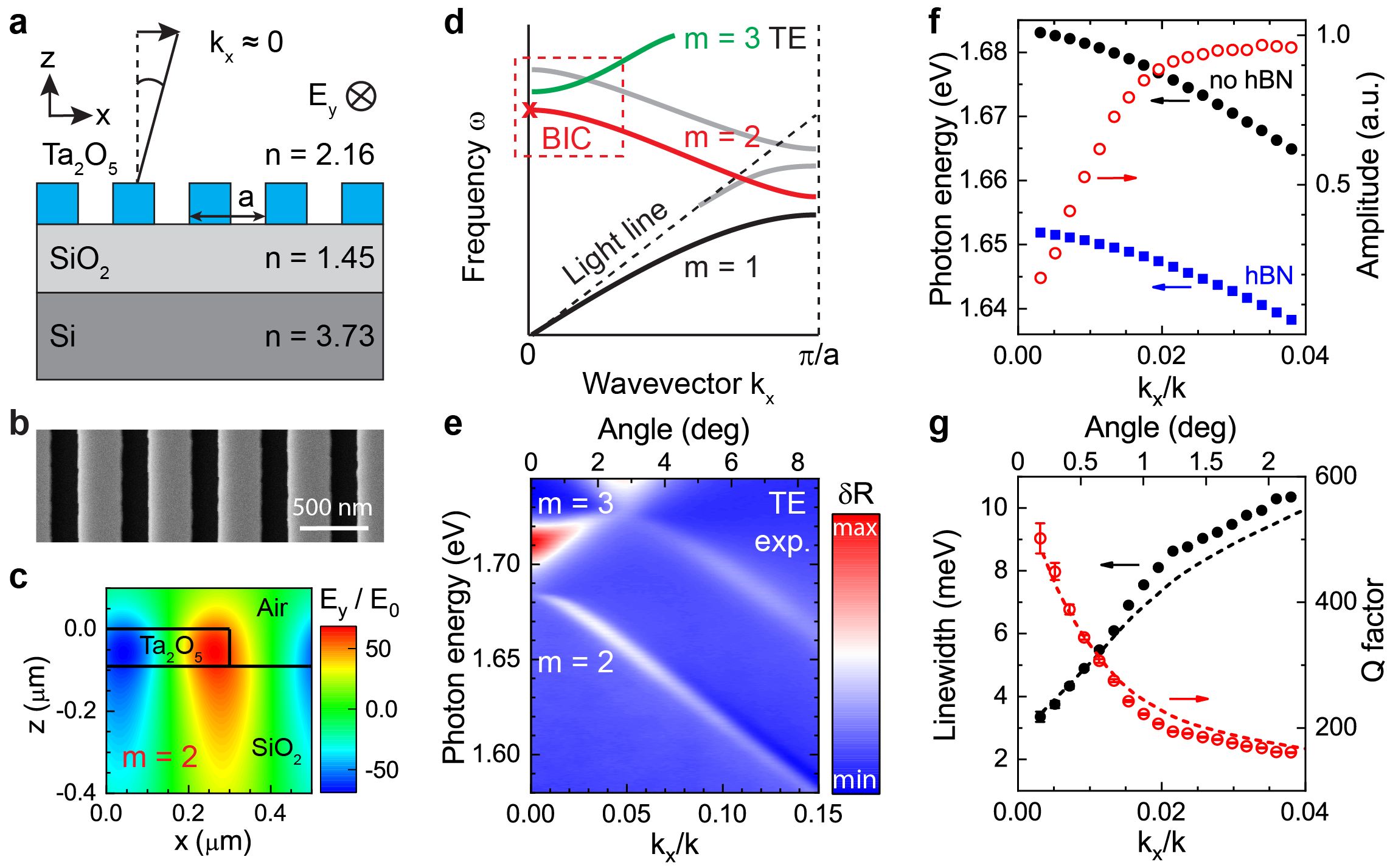
In the experiment, we fabricate a 1D photonic crystal slab (PCS) sample consisting of 90 nm thick Ta2O5 bars on a SiO2/Si (1 µm/500 µm) substrate as schematically shown in Fig. 1a, with a scanning electron microscopy image in (b). The PCS geometry (see Methods) is designed for large refractive index modulation, in order to open a photonic band gap and support an optical BIC close to the exciton resonance in monolayer MoSe2. As illustrated in the photonic band structure shown in Fig. 1d, the BIC is expected to form on the lower-energy TE mode (red) at the point in the crystal momentum () space Koshelev2018 , with characteristic confinement and antisymmetric spatial distribution of the optical field (c).
We measure the PCS band structure via angle-resolved reflectance spectroscopy (see Methods and Supplementary Fig. S1). Fig. 1e shows experimental differential reflectance spectra for varying angle, where the signal from the un-patterned Ta2O5/SiO2/Si substrate is subtracted for clarity: . Three modes, one broad symmetric () and two narrower antisymmetric (), are clearly observed in the figure, in agreement with theory (d, red dashed box). We fit the lower-energy antisymmetric mode peak in reflectance spectra using a Fano-like line shape with resonance frequency , linewidth , and asymmetry parameter , which arises due to interference with the broad symmetric mode and even broader Fabry-Perot response of the layered substrate (see Supplementary Fig. S2).
Extracted Fano fit parameters are plotted in Fig. 1f,g as functions of the in-plane wavevector component . Towards the point (), the reflectivity associated with the mode sharply decreases (f, red), while the spectral line narrows (g, black circles) resulting in sharply increasing Q-factor (g, red open circles), defined as . Such behavior is characteristic of an at- optical BIC Hsu2013 , where interference of optical waves outgoing in opposite directions leads to effective light trapping in the near field and vanishing far-field radiation. This is in contrast to the case studied recently Zhang2018 ; Gogna2019 , where only radiating PCS modes with smaller and largely angle-independent Q-factors were considered for strong coupling to excitons in 2D semiconductors.
The theoretically predicted radiative Q-factor of BIC diverges towards infinity at . In practice, the measured Q-factor is limited predominantly by non-radiative losses Hsu2013 ; Jin2018 . The two major contributions in our case are (i) intrinsic absorption in Ta2O5 and (ii) surface roughness induced symmetry breaking and scattering Sadrieva2017 , limiting Q to . Additional resonance broadening comes from leaky losses in Si due to near-field penetration through SiO2 layer Sadrieva2017 and finite sample size effects Grepstad2013 ; Lee2012 . We perform Fourier modal method (FMM) simulations, taking into account these four loss mechanisms (see Supplementary Note 1 and Fig. S3). As seen in Fig. 1g (dashed lines), good agreement with experiment can be achieved considering scattering losses through an additional imaginary part of Ta2O5 refractive index (Fig. 1g, dashed lines).
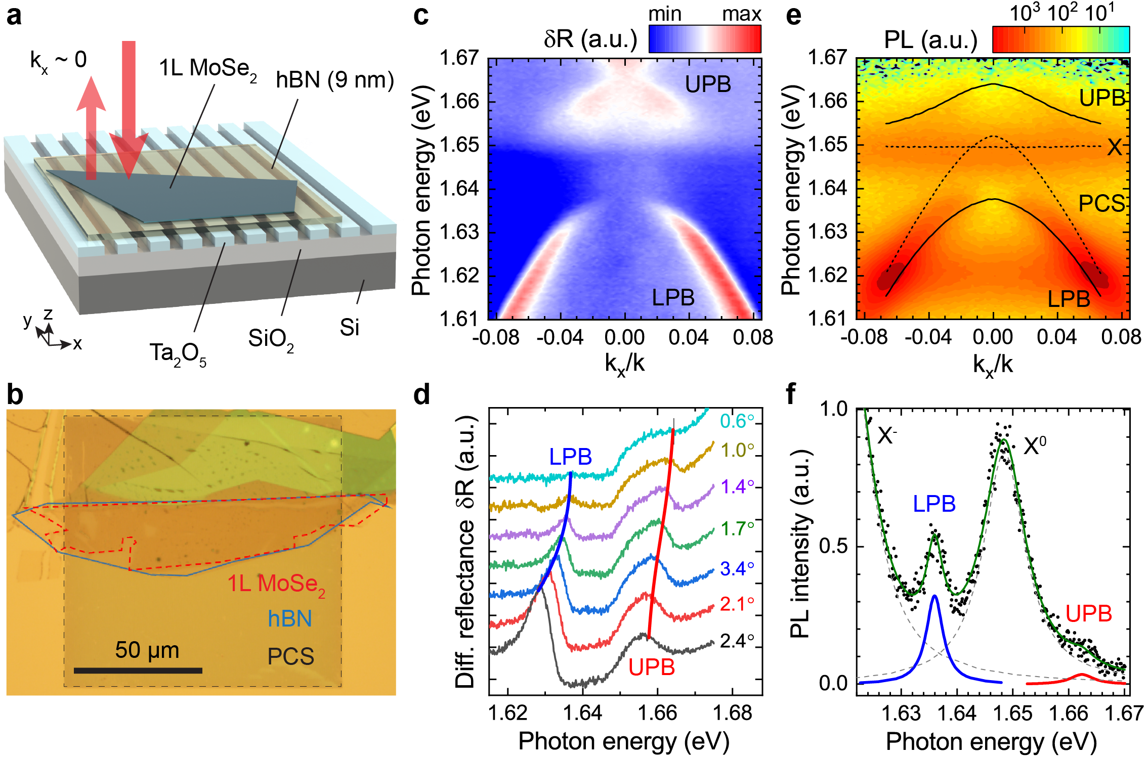
We then create polaritons by coupling the observed BIC to excitons in a vertically stacked 1L MoSe2/hBN/PCS structure illustrated in Fig. 2a. To maximize the Q-factor of resulting polariton modes, we use large-area multilayer hBN and monolayer MoSe2 flakes of µm in size, covering periods of PCS, as demonstrated in an optical microscope image in (b). The hBN spacer plays a three-fold role: it avoids MoSe2 flake “sagging” into PCS grooves, reduces influence of Ta2O5 surface roughness, and provides tunability of the BIC frequency through hBN thickness. In our case, a 9 nm thick hBN spacer shifts the PCS mode and spectral position of BIC by meV to bring it close to resonance with the neutral exciton in 1L MoSe2 at 7 K eV (Fig. 1f, blue squares).
We study polaritons experimentally via angle-resolved reflectivity and PL measurements at 7 K (see Methods), with the results for TE-polarized detection shown in Fig. 2c-f. In comparison to Fig. 1e, the lower-energy antisymmetric PCS mode observed in reflectivity (Fig. 2c,d) is now redshifted by meV due to the presence of hBN/MoSe2 and split into upper and lower polariton branches (UPB, LPB) due to strong coupling with the neutral exciton in 1L MoSe2 centered at eV. Both LPB and UPB retain BIC-like behavior near the point, exhibiting several distinctive properties.
First, at the point both LPB and UPB are “dark” as radiation into the far-field becomes symmetry-forbidden, effectively extending interaction time for potential enhancement of optical nonlinearities. Second, close to the point polaritons possess negative effective mass and associated negative group velocity inherited from the PCS mode, providing a potential platform for studying TMD-based polariton self-focusing and soliton formation. Third, the strong variation of the PCS mode linewidth in the vicinity of the BIC results in wavevector-dependent Q-factor of both LPB and UPB, enabling control of polariton linewidth with angle.
Further details of the optical response are revealed by TE-polarized angle-resolved PL spectra (e), showing emission from both polariton branches and the uncoupled neutral exciton (X0). The latter is increasingly enhanced towards small wavevectors and exhibits a slight redshift of meV, which we attribute to weak coupling to the higher-frequency and broader symmetric mode (see Supplementary Note 2 and Fig. S4). Charged exciton (trion, X-) emission is also observed at meV independent of , implying weak coupling.
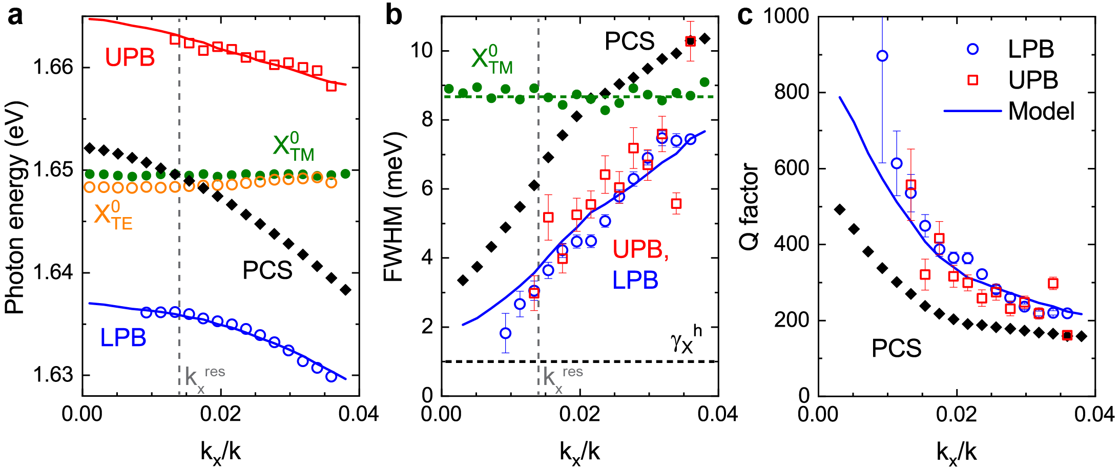
We analyze the wavevector-dependent behavior of LPB, UPB, uncoupled neutral exciton, and trion by fitting the PL spectra for each with 4 Lorentzian functions , as shown Fig. 2f, and extracting the spectral position and linewidth as full width at half maximum (FWHM) for each peak. The extracted parameters are plotted as functions of in-plane wavevector in Fig. 3, with spectral positions (a) for UPB (red symbols), LPB (blue symbols), and uncoupled neutral exciton (orange symbols), corresponding values of FWHM (b), and calculated Q-factors (c). Parameters of uncoupled excitons, extracted from TM-polarized PL, are plotted as green dots.
We then fit the extracted spectral positions of UPB () and LPB () with a coupled oscillator model Hopfield1958 , using spectral position and homogeneous linewidth for the uncoupled neutral exciton and for the PCS/hBN mode :
Here, is Rabi splitting between UPB and LPB, and the two fit parameters are the coupling strength and additional spectral shift of the PCS mode Zhang2018 due to the presence of 1L MoSe2. The fit curves for the spectral position of UPB and LPB are shown in Fig. 3a by red and blue solid lines, respectively. The uncoupled PCS/hBN mode, indicated by black squares, comes into resonance with the uncoupled neutral exciton at , corresponding to an angle of . From the fits in Fig. 3a we extract a coupling strength of meV, which corresponds to a Rabi splitting of meV and splitting-to-linewidth ratio of , exceeding the values recently reported for a WSe2/PCS system Zhang2018 and theoretical estimates for strong coupling to an optical BIC Koshelev2018 . As is larger than the sum of the exciton ( meV) and PCS mode linewidth ( meV), the hybrid MoSe2/hBN/PCS system is unambiguously in the strong coupling regime.
Quantitatively, the polariton linewidth is expected to vary between that of the exciton () and PCS modes () depending on the excitonic fraction in the polariton. However, our experimentally observed values of polariton linewidth (Fig. 3b, open circles) close to resonance are significantly smaller than both (green) and (black). We attribute this to polariton motional narrowing, similar to the effects studied previously for quantum wells in microcavities Whittaker1996 ; Savona1997 ; Kavokin1998 ; Whittaker1998 ; Skolnick1998 .
Here, the large polariton mode size (10’s of µm) together with large Rabi splitting lead to effective averaging over excitonic disorder Rhodes2019 in 1L MoSe2 on a broad (nm–µm) range of length scales. As a result, the excitonic contribution to the polariton FWHM close to resonance is given by only the homogeneous exciton linewidth Houdre1996 , while away from resonance, where the polariton frequency overlaps with the exciton peak, it changes towards the inhomogeneous linewidth due to increasing interaction with disorder and associated scattering with higher-momenta excitonic states as well as absorption Whittaker1998 ; Walker2017 . We use a phenomenological model that accounts for homogeneous and inhomogeneous contributions to the polariton linewidth (see Supplementary Note 3). The model shows good agreement with experimental data (Fig. 3b, blue line) for a homogeneous linewidth of meV (b, black dashed line), which is within the range of recently reported values Ajayi2017 ; Scuri2018 ; Martin2018 ; Fang2019 for the low-temperature radiative decay rate of excitons in monolayer MoSe2.
As a result of excitonic and photonic disorder averaging, the Q-factors achieved for polaritons around the point in our structure are times higher than those for the bare PCS mode (Fig. 3c), reaching . This provides potential for further improvement of polariton linewidth through fabrication of macroscopic photonic crystal samples Lee2012 with improved surface quality and use of large TMD flakes grown by chemical vapor deposition. In addition, the strongly -dependent Q-factor of the PCS mode in the vicinity of the BIC enables precise control of polariton linewidth and corresponding Q-factors via angle or temperature tuning (see Supplementary Note 4 and Figs. S5,S6).
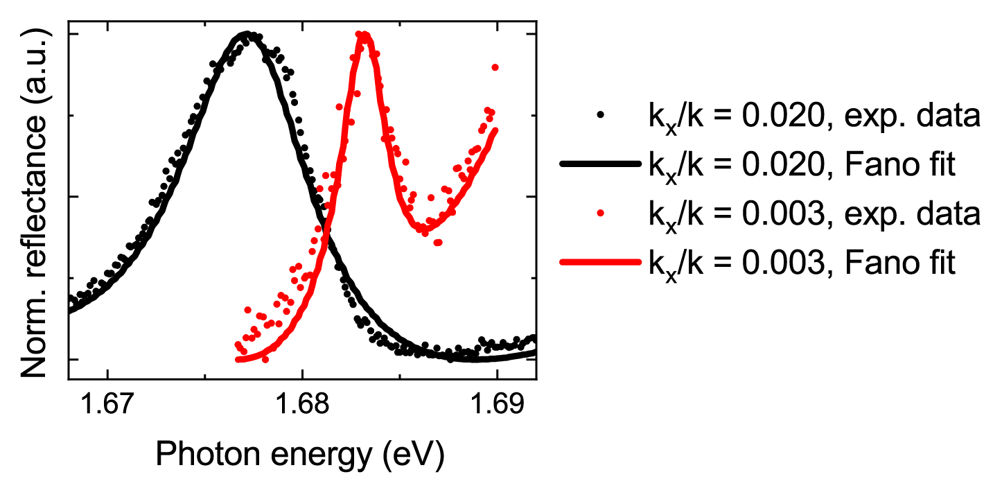
Mixing photonic modes with excitons in our hybrid MoSe2/hBN/PCS structures leads to a dramatic enhancement of the associated optical nonlinearities. We probe the underlying polariton–polariton interaction due to the excitonic contribution by measuring pump-dependent frequency shifts of polariton peaks in the reflectivity spectra. Polariton modes are excited resonantly in both frequency and wavevector domains by fs laser pulses (Fig. 4a, inset), with incident fluence varying from 0.1 µJ/cm2 to 3.0 µJ/cm2 (see Methods).
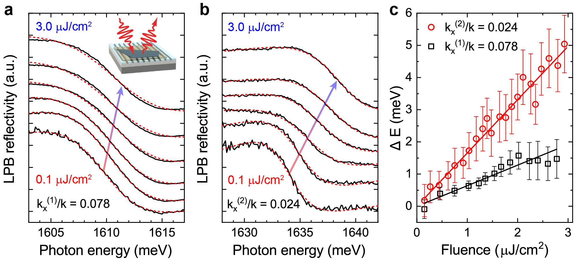
Figs. 4a,b show the measured pump-dependent reflectivity spectra of the LPB resonance (solid black curves) for selected values of incident fluence, increasing from bottom to top, and for two different x-components of wavevector: (a) and (b). Due to exciton–exciton interaction, increasing with the density of created quasiparticles Shahnazaryan2017 , lower-energy polariton resonance in the reflectivity spectra is continuously shifted with fluence towards higher energies. We observe larger blueshifts (b) for wavevectors closer to the anticrossing condition , as expected for the increasing exciton fraction in LPB associated with stronger polariton–polariton interaction.
Fig. 4c shows the blueshift values for (black squares) and (red circles) extracted from Fano lineshape fitting (a-b, red dashed curves) for varying fluence, together with corresponding linear fits (black and red lines). Calculating polariton density for each fluence (see Supplementary Note 5), we obtain the polariton–polariton interaction strength of µeVµm2 and µeVµm2. Further, from the dependence on the Hopfield coefficient , which describes the exciton fraction in the polariton, we estimate the exciton–exciton interaction strength in our measurement as µeVµm2. This is of the same order as the theoretical estimate µeVµm2, as well as the value µeVµm2 we extract from a direct measurement of pump-dependent excitonic blueshifts in TM polarization (see Supplementary Note 6), and is considerably larger than the numbers recently reported for WS2-based polaritons Barachati2018 , where the estimation of exciton–exciton interaction strength was possibly uncertain due to local heating and higher-order interaction effects Note1 .
As exciton densities in our experiment ( cm-2) are far below the Mott transition density ( cm-2), phase space filling effects are not important, and the observed polariton nonlinearity is dominated by exciton–exciton interaction. Additionally, we note that the observed nonlinearities are fast at least on a 100 fs scale, providing future opportunities for developing polariton-based ultrafast modulators and switches.
In summary, we present the first experimental demonstration and investigation of optical BIC-based polaritonic excitations.
The formation of BIC-like polaritons in a hybrid system of a monolayer semiconductor interfaced with a photonic crystal slab, with suppressed radiation into far-field and line narrowing due to effective disorder averaging, extends the polariton–polariton interaction time for an enhancement of the nonlinear optical response.
In future, such “dark” states can be accessed through near fields, using guided modes excited via grating-coupling, or by nonlinear frequency conversion.
With the strength of the underlying exciton–exciton interaction of µeVµm2, our polaritons exhibit strong exciton-fraction-dependent optical nonlinearities that are fast on a 100 fs time scale.
Additionally, the planar geometry of our structure in principle allows straightforward fabrication of electrical contacts for electrostatic control of polaritons and associated interactions, while the use of atomically thin semiconductors allows room temperature operation.
Thus, the formation of BIC-based polaritons can enable not only significantly enhanced but also controllable and fast nonlinear optical responses in photonic crystal systems due to the strong excitonic interaction in monolayer semiconductors and open a new way to develop active and nonlinear all-optical on-chip devices.
Methods
Sample fabrication.
Ta2O5 layers of 90 nm thickness were deposited on commercial SiO2/Si substrates via e-beam assisted ion-beam sputtering.
Photonic crystal slabs were fabricated by patterning the Ta2O5 layers via combination of electron-beam lithography and by plasma etching to yield the following geometric parameters: pitch nm, groove width nm, and depth nm, characterized with scanning electron and atomic force microscopy measurements.
Large-area high quality flakes of multilayer hBN and monolayer MoSe2 were mechanically exfoliated from commercial bulk crystals (HQ Graphene) and stacked vertically onto the photonic crystal sample surface via dry transfer to form a hybrid 1L MoSe2/hBN/PCS structure.
Optical measurements.
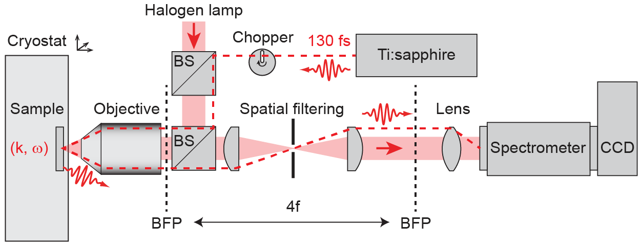
Angle-resolved reflectance spectroscopy was performed in a back focal plane setup with a slit spectrometer coupled to a liquid nitrogen cooled imaging CCD camera (Princeton Instruments SP2500+PyLoN), using white light from a halogen lamp for illumination (see Supplementary Fig. S1).
For pump-dependent reflectivity measurements, the sample was excited by 130 fs pulses from a wavelength-tunable Ti:sapphire oscillator (Spectra-Physics, Tsunami, 80 MHz repetition rate) with wavevector control via laser beam positioning within the back focal plane of the objective.
A single-slit optical chopper with a duty cycle of 0.001 was used in the laser beam to avoid sample heating.
Angle-resolved photoluminescence (PL) measurements were performed in the same setup with off-resonant excitation by monochromatic light from a HeNe laser with wavelength nm.
The sample was mounted in an ultra low vibration closed cycle helium cryostat (Advanced Research Systems) and maintained at controllable temperature in a K range.
The cryostat was mounted on a precise xyz stage for sample positioning.
Spatial filtering in the detection channel was used to selectively measure signals from the 1L MoSe2/hBN/PCS sample area.
Data availability.
The data that support the plots within this paper and other findings of this study are available from the corresponding author upon reasonable request.
Acknowledgements
The authors acknowledge funding from Ministry of Education and Science of the Russian Federation Megagrant No. 14.Y26.31.0015, GosZadanie No. 3.1365.2017/4.6, and GosZadanie No. 3.8891.2017/8.9. A.I.T. and D.N.K. acknowledge UK EPSRC grant EP/P026850/1.
V.K. acknowledges financial support from ITMO Fellowship Program.
This work was carried out using equipment of the SPbU Resource Centers “Nanophotonics” and “Nanotechnology”.
We thank M. Zhukov, A. Bukatin, and A. Chezhegov for assistance with sample characterization and A. Bogdanov for helpful discussion.
Competing interests
The authors declare no competing financial interests.
Additional information
Supplementary Information is available for this paper at
References
- (1) Marinica, D., Borisov, A. & Shabanov, S. Bound states in the continuum in photonics. Phys. Rev. Lett. 100, 183902 (2008).
- (2) Hsu, C. W., Zhen, B., Stone, A. D., Joannopoulos, J. D. & Soljačić, M. Bound states in the continuum. Nat. Rev. Mater. 1, 16048 (2016).
- (3) Lee, J. et al. Observation and differentiation of unique high-Q optical resonances near zero wave vector in macroscopic photonic crystal slabs. Phys. Rev. Lett. 109, 067401 (2012).
- (4) Jin, J. et al. Topologically enabled ultra-high-Q guided resonances robust to out-of-plane scattering. arXiv preprint arXiv:1812.00892 (2018).
- (5) Krasikov, S., Bogdanov, A. & Iorsh, I. Nonlinear bound states in the continuum of a one-dimensional photonic crystal slab. Phys. Rev. B 97, 224309 (2018).
- (6) Bulgakov, E. N. & Maksimov, D. N. Nonlinear response from optical bound states in the continuum. arXiv preprint arXiv:1902.05782 (2019).
- (7) Walker, P. et al. Ultra-low-power hybrid light–matter solitons. Nat. Commun. 6, 8317 (2015).
- (8) Sich, M., Skryabin, D. V. & Krizhanovskii, D. N. Soliton physics with semiconductor exciton–polaritons in confined systems. C. R. Phys. 17, 908–919 (2016).
- (9) Kodigala, A. et al. Lasing action from photonic bound states in continuum. Nature 541, 196 (2017).
- (10) Foley, J. M., Young, S. M. & Phillips, J. D. Symmetry-protected mode coupling near normal incidence for narrow-band transmission filtering in a dielectric grating. Phys. Rev. B 89, 165111 (2014).
- (11) Romano, S. et al. Surface-enhanced Raman and fluorescence spectroscopy with an all-dielectric metasurface. J. Phys. Chem. C 122, 19738–19745 (2018).
- (12) Romano, S. et al. Optical biosensors based on photonic crystals supporting bound states in the continuum. Materials 11, 526 (2018).
- (13) Khitrova, G., Gibbs, H., Jahnke, F., Kira, M. & Koch, S. W. Nonlinear optics of normal-mode-coupling semiconductor microcavities. Rev. Mod. Phys. 71, 1591 (1999).
- (14) Dufferwiel, S. et al. Exciton–polaritons in van der Waals heterostructures embedded in tunable microcavities. Nat. Commun. 6, 8579 (2015).
- (15) Liu, X. et al. Strong light–matter coupling in two-dimensional atomic crystals. Nat. Photonics 9, 30 (2015).
- (16) Lundt, N. et al. Room-temperature Tamm-plasmon exciton-polaritons with a WSe2 monolayer. Nat. Commun. 7, 13328 (2016).
- (17) Dibos, A. M. et al. Electrically tunable exciton–plasmon coupling in a WSe2 monolayer embedded in a plasmonic crystal cavity. Nano Lett. (2019).
- (18) Zhang, L., Gogna, R., Burg, W., Tutuc, E. & Deng, H. Photonic-crystal exciton-polaritons in monolayer semiconductors. Nat. Commun. 9, 713 (2018).
- (19) Gogna, R., Zhang, L., Wang, Z. & Deng, H. Photonic crystals for controlling strong coupling in van der Waals materials. Opt. Express 27, 22700–22707 (2019).
- (20) Barachati, F. et al. Interacting polariton fluids in a monolayer of tungsten disulfide. Nat. Nanotechnol. 13, 906 (2018).
- (21) Koshelev, K., Sychev, S., Sadrieva, Z., Bogdanov, A. & Iorsh, I. Strong coupling between excitons in transition metal dichalcogenides and optical bound states in the continuum. Phys. Rev. B 98, 161113 (2018).
- (22) Ferrier, L. et al. Interactions in confined polariton condensates. Phys. Rev. Lett. 106, 126401 (2011).
- (23) Sich, M. et al. Observation of bright polariton solitons in a semiconductor microcavity. Nat. Photon. 6, 50 (2012).
- (24) Hsu, C. W. et al. Observation of trapped light within the radiation continuum. Nature 499, 188 (2013).
- (25) Sadrieva, Z. F. et al. Transition from optical bound states in the continuum to leaky resonances: role of substrate and roughness. ACS Photonics 4, 723–727 (2017).
- (26) Grepstad, J. O. et al. Finite-size limitations on quality factor of guided resonance modes in 2D photonic crystals. Opt. Express 21, 23640–23654 (2013).
- (27) Hopfield, J. Theory of the contribution of excitons to the complex dielectric constant of crystals. Phys. Rev. 112, 1555 (1958).
- (28) Whittaker, D. et al. Motional narrowing in semiconductor microcavities. Phys. Rev. Lett. 77, 4792 (1996).
- (29) Savona, V., Piermarocchi, C., Quattropani, A., Tassone, F. & Schwendimann, P. Microscopic theory of motional narrowing of microcavity polaritons in a disordered potential. Phys. Rev. Lett. 78, 4470 (1997).
- (30) Kavokin, A. V. Motional narrowing of inhomogeneously broadened excitons in a semiconductor microcavity: Semiclassical treatment. Phys. Rev. B 57, 3757 (1998).
- (31) Whittaker, D. What determines inhomogeneous linewidths in semiconductor microcavities? Phys. Rev. Lett. 80, 4791 (1998).
- (32) Skolnick, M., Fisher, T. & Whittaker, D. Strong coupling phenomena in quantum microcavity structures. Semicond. Sci. Technol. 13, 645 (1998).
- (33) Rhodes, D., Chae, S. H., Ribeiro-Palau, R. & Hone, J. Disorder in van der Waals heterostructures of 2D materials. Nat. Mater. 18, 541 (2019).
- (34) Houdré, R., Stanley, R. & Ilegems, M. Vacuum-field Rabi splitting in the presence of inhomogeneous broadening: Resolution of a homogeneous linewidth in an inhomogeneously broadened system. Phys. Rev. A 53, 2711 (1996).
- (35) Walker, P. et al. Dark solitons in high velocity waveguide polariton fluids. Phys. Rev. Lett. 119, 097403 (2017).
- (36) Ajayi, O. A. et al. Approaching the intrinsic photoluminescence linewidth in transition metal dichalcogenide monolayers. 2D Mater. 4, 031011 (2017).
- (37) Scuri, G. et al. Large excitonic reflectivity of monolayer MoSe2 encapsulated in hexagonal boron nitride. Phys. Rev. Lett. 120, 037402 (2018).
- (38) Martin, E. W. et al. Encapsulation narrows excitonic homogeneous linewidth of exfoliated MoSe2 monolayer. arXiv preprint arXiv:1810.09834 (2018).
- (39) Fang, H. et al. Control of the exciton radiative lifetime in van der Waals heterostructures. arXiv preprint arXiv:1902.00670 (2019).
- (40) Shahnazaryan, V., Iorsh, I., Shelykh, I. & Kyriienko, O. Exciton-exciton interaction in transition-metal dichalcogenide monolayers. Phys. Rev. B 96, 115409 (2017).
- (41) Experiments in Ref. Barachati2018 are performed at 300 K, so that heating effects might play a significant role at high powers, resulting in spectral redshifts reducing the observed blueshifts; in addition, due to the broad polariton lines, the energy shifts of meV require quite high excitation densities, at which higher-order effects (three particle exciton–exciton interactions) become important and may lead to redshifts rather than blueshifts, reducing the overall observed nonlinear response.
Supplementary Information: Nonlinear polaritons in monolayer semiconductor coupled to optical bound states in the continuum
Supplementary Note 1. BIC Q-factor simulations
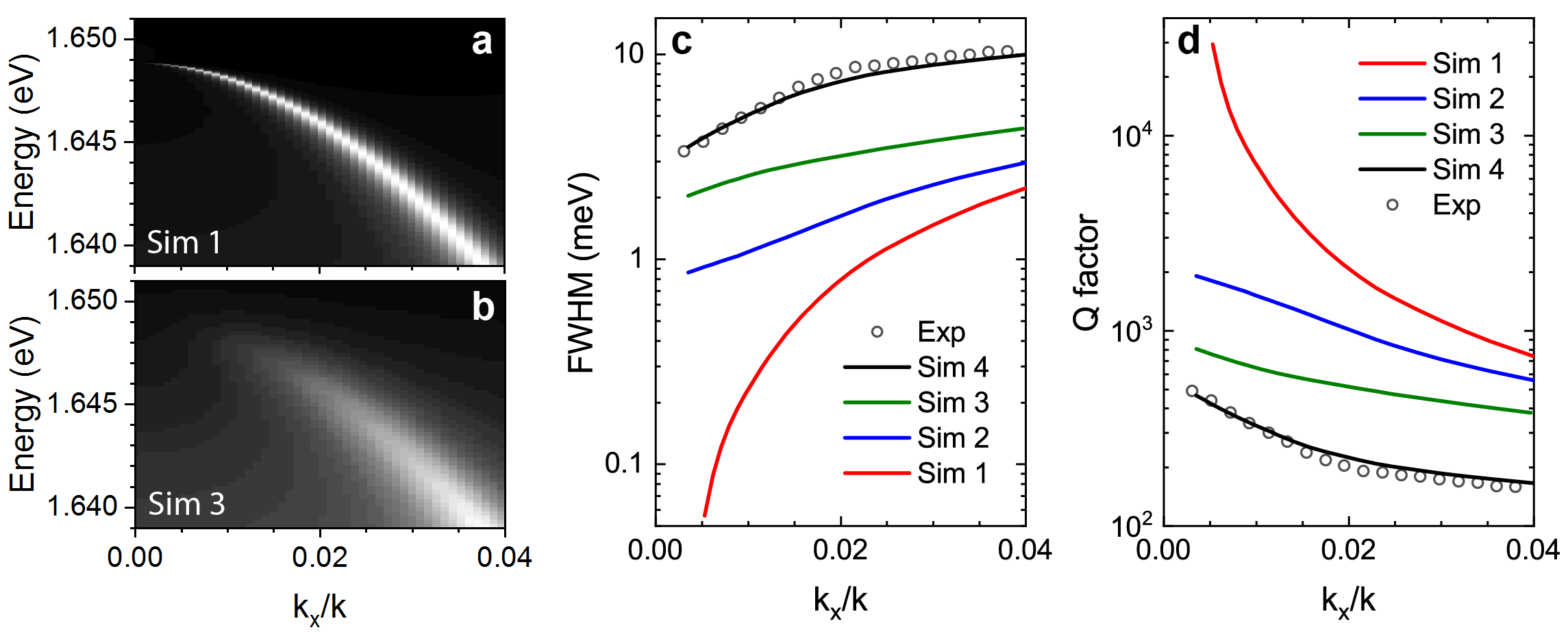
With diverging to infinity radiative Q-factors of optical BICs in photonic crystal slabs (PCSs), their total Q-factors are limited by nonradiative terms, including material absorption, surface roughness induced scattering, leakage through the oxide layer into the Si substrate, and losses due to the finite sample size. To estimate Q-factors achievable in our experimental system, we perform simulations of their optical response using the Fourier modal method (FMM) Li1997 . We first simulate a patterned Ta2O5/SiO2/Si structure with the experimental parameters (Ta2O5 thickness of 90 nm, SiO2 thickness of 1 µm, pitch nm, groove width nm, and depth nm), but ignoring losses in Ta2O5 (setting the imaginary part of its refractive index to zero).
The resulting dispersion of the lower-energy antisymmetric mode is shown as angle-resolved reflectivity spectra in Fig. S3a and labeled as Sim 1. Fitting the reflectivity spectra for different wavevectors with Fano-like shape as discussed in the main text, we obtain the wavevector dependence of the mode linewidth plotted in (c) with a red curve. The corresponding Q-factor of the mode is plotted in (d) as a red curve and reveals a sharp increase towards the point, with Q-factors reaching at and growing further towards .
In contrast, when taking into account the absorption losses in Ta2O5, the Q-factors are limited by , as indicated in (c) and (d) with a blue curve (labeled as Sim 2). To describe our experimental data, we account for additional scattering losses due to surface roughness via an extra imaginary term in the refractive index of Ta2O5, (Sim 3), with linewidth and Q-factor shown in (c) and (d) with green curves, and dispersion shown in (b). Then, a convolution of the resulting lineshape with a Gaussian function that accounts for the finite sample size of µm yields linewidth and corresponding Q-factor as shown with a black curve in (c) and (d). Experimental values (open black circles) are also plotted for reference. Overall, the absorption in Ta2O5 is seen to be the major limiting factor for the BIC linewidth in this case.
Supplementary Note 2. Measurements in TE vs. TM polarization
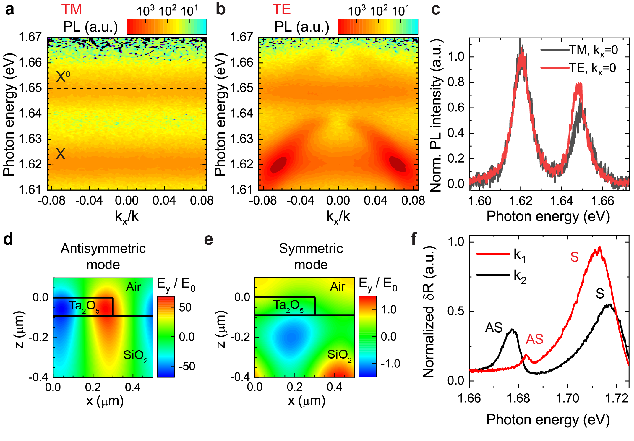
In TM polarization (E-field perpendicular to the grooves), the MoSe2 exciton is far detuned from the photonic crystal mode. As shown in Fig. S4a, PL spectra detected in TM polarization reveal only wavevector-independent uncoupled neutral exciton (X0) and trion (X-) emission. In TE polarization, in addition to the upper and lower polariton branches as well as the trion peak, our experimental PL spectra (b) show emission close to the frequency of the uncoupled neutral exciton in 1L MoSe2 with a slight redshift of meV and enhancement as compared to the spectra measured in TM polarization (c).
This behavior is due to coupling to the symmetric PCS mode lying at higher energies. While the strongly coupled to the exciton antisymmetric mode exhibits a tightly confined and enhanced electric field distribution (d), the symmetric mode is less confined, resulting in a weaker coupling, which, together with a larger detuning from the exciton resonance, leads to only a small “Lamb” redshift and slight enhancement of the exciton emission. The corresponding narrow antisymmetric (AS) and broader symmetric (S) peaks observed in the PCS reflectivity spectra are shown in (f) for two different wavevectors.
Supplementary Note 3. Polariton linewidth model
Since the Rabi splitting well exceeds the inhomogeneous exciton linewidth in our case, the polariton linewidth close to the anticrossing point () will be defined through only the homogeneous contribution to the exciton linewidth Houdre1996suppl . We describe the experimentally obtained polariton linewidth with a phenomenological model taking into account both homogeneous and inhomogeneous exciton linewidth, and . The effect of motional narrowing Whittaker1996suppl results in the dependence of the polariton linewidth on the effective mass Mattuck1974 , which is incorporated in our model as
| (S1) |
where , are effective masses of the polaritons and exciton, respectively, and , are the Hopfield coefficients:
| (S2) |
An agreement between the model and experimental LPB linewidth is reached for meV, which is close to recently reported values Ajayi2017suppl ; Scuri2018suppl ; Fang2019suppl for the low-temperature radiative decay rate of excitons in monolayer MoSe2 of meV, implying that the homogeneous non-radiative contribution to MoSe2 exciton linewidth at 7 K is small. Assuming a Voigt profile of the exciton line at 7 K, we estimate the inhomogeneous linewidth of meV. The total homogeneous linewidth is then used to fit our experimentally measured dispersion with the coupled oscillator model at each temperature.
Supplementary Note 4. Variable temperature measurements
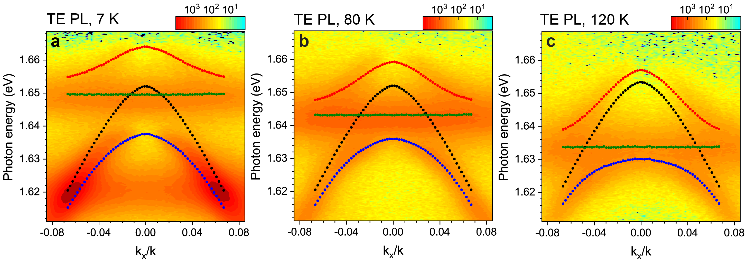
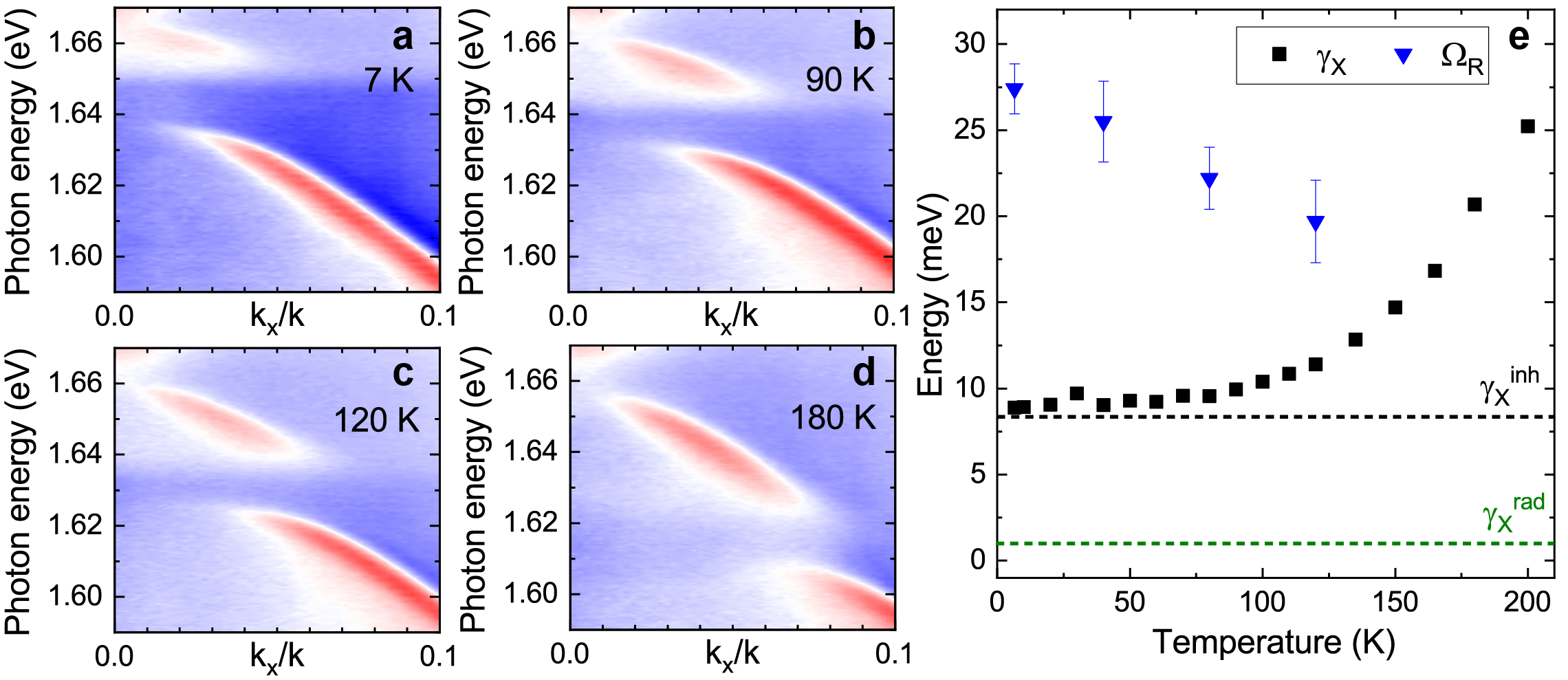
With increasing temperature, the neutral MoSe2 exciton shifts towards lower energies, effectively tuning the polariton dispersion. Fig. S5 shows experimental angle-resolved PL spectra for 3 selected temperatures of 7 K (a), 80 K (b), and 120 K (c), with the uncoupled PCS mode dispersion (black), uncoupled exciton (green), and upper and lower polariton branches (red and blue, respectively), as obtained by fitting the PL data with the coupled oscillator model. The temperature dependence of the polariton dispersion is also observed in reflectivity spectra (Fig. S6a-d). We extract a temperature-dependent coupling constant (e, blue triangles) and compare it with the exciton linewidth (black squares). The clear signatures of strong coupling persist up to at least 150 K where exciton broadening starts to blur the observed anticrossing behavior.
Supplementary Note 5. Polariton nonlinearity
The nonlinear polaritonic shift can be estimated as Barachati2018suppl
| (S3) |
where is the exciton–exciton interaction constant, is the exciton Hopfield coefficient for the corresponding polariton mode, and is the polariton wavefunction. For the pulsed excitation case, is time-dependent; for the nonlinear shift modelling, the wavefunction is evaluated at the moment of time when it acquires the largest value.
For a pulsed pump with spectral width and polaritonic mode with radiative decay rate , the polaritonic wavefunction can be estimated (in the rectangular pulse shape approximation) as
| (S4) |
where is the saturated wavefunction, which corresponds to the case of continuous wave excitation.
The saturated wavefunction can be estimated as
| (S5) |
where is the peak power density, is the polariton frequency, and is the dimensionless field distribution of the eigenmode when it is excited by a plane wave of the unity amplitude and frequency . is calculated numerically using the Fourier modal method (FMM). It should be noted though that the general result of the temporal coupled mode theory Fan2003 states that is proportional to .
The average polariton density is given by
| (S6) |
where is the period of the structure. The upper bound for the polariton density for the maximum fluence of can be estimated as . Thus, we are quite far from the Mott transition densities , and phase space filling effects can be neglected.
Finally, the polariton shift is given by
| (S7) |
The values of and can be calculated for each wavevector. For example, for the two wavevectors corresponding to the data in Fig. 4 in the main text, these values are estimated as for and for . At the maximum fluence this corresponds to polariton densities m-2 for and m-2 for . From the dependence of the polariton shift on the exciton Hopfield coefficient , the exciton–exciton interaction strength can then be evaluated as .
Supplementary Note 6. Exciton nonlinearity
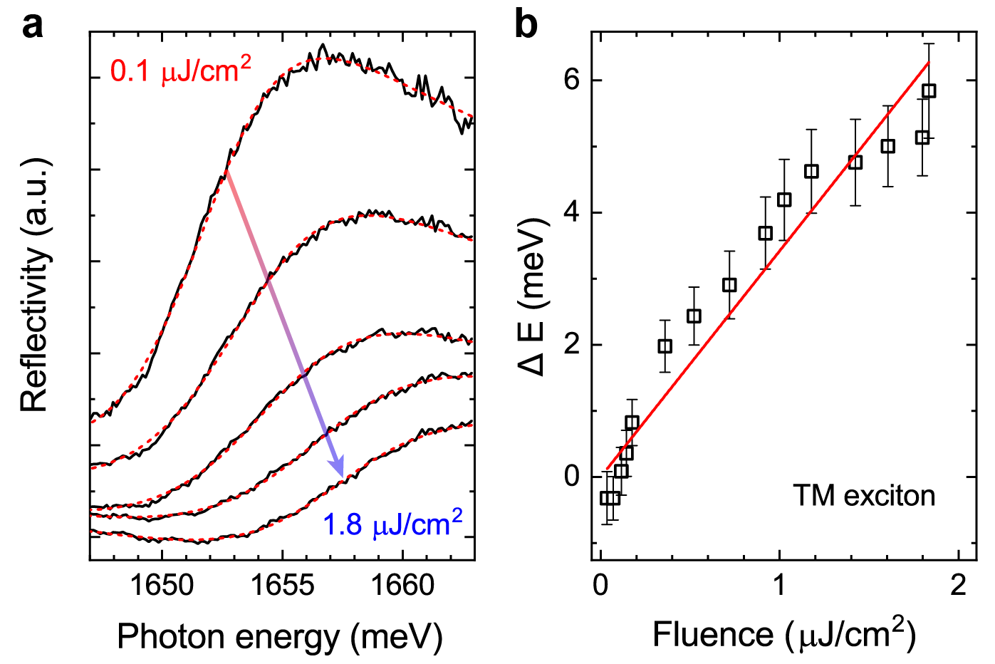
We measure the pump-dependent blueshift of the exciton resonance in reflectance with TM-polarized excitation. The corresponding reflectance spectra are shown in Fig. S7a for selected values of fluence varying from 0.1 µJ/cm2 (top) to 1.8 µJ/cm2 (bottom). We fit the experimentally measured spectra with a Fano-like shape to obtain pump-dependent blueshift shown in Fig. S7b with open squares. The exciton concentration for each fluence can be evaluated in the linear regime (omitting the effects of phase space filling) from the differential equation for the exciton annihilation operator :
| (S8) |
where is the pulse duration, is the reflection coefficient of the substrate, and is the square root of the number of photons passing through the monolayer per unit time per unit area, which is related to the peak incident power density as . We have substituted the bosonic operator with the complex amplitude. This differential equation can be solved explicitly yielding for
| (S9) |
where , , and is at the pulse centre. To account for the inhomogeneous broadening, we should convolve the expression for N with the gaussian distribution of the exciton frequency with the width :
| (S10) |
This integral can not be taken analytically. For meV, fs, and meV, the numerical integration returns a function of time with a maximum at .
In the case of TM polarization the reflection coefficient is almost constant across the pulse bandwidth, and , yielding . can be expressed through fluence as .
Finally, the exciton concentration N for fluence will be
| (S11) |
Then can be evaluated as .
We compare the obtained value with a theoretical estimate Shahnazaryan2017suppl of , where eV is the exciton binding energy in monolayer MoSe2 and nm is the corresponding exciton Bohr radius Li2015 .
References
- (1) Li, L. New formulation of the Fourier modal method for crossed surface-relief gratings. J. Opt. Soc. Am. A 14, 2758–2767 (1997).
- (2) Houdré, R., Stanley, R. & Ilegems, M. Vacuum-field Rabi splitting in the presence of inhomogeneous broadening: Resolution of a homogeneous linewidth in an inhomogeneously broadened system. Phys. Rev. A 53, 2711 (1996).
- (3) Whittaker, D. et al. Motional narrowing in semiconductor microcavities. Phys. Rev. Lett. 77, 4792 (1996).
- (4) Mattuck, R. D. A guide to Feynman diagrams in the many-body problem (Courier Corporation, 1974).
- (5) Ajayi, O. A. et al. Approaching the intrinsic photoluminescence linewidth in transition metal dichalcogenide monolayers. 2D Mater. 4, 031011 (2017).
- (6) Scuri, G. et al. Large excitonic reflectivity of monolayer MoSe2 encapsulated in hexagonal boron nitride. Phys. Rev. Lett. 120, 037402 (2018).
- (7) Fang, H. et al. Control of the exciton radiative lifetime in van der Waals heterostructures. arXiv preprint arXiv:1902.00670 (2019).
- (8) Barachati, F. et al. Interacting polariton fluids in a monolayer of tungsten disulfide. Nat. Nanotechnol. 13, 906 (2018).
- (9) Fan, S., Suh, W. & Joannopoulos, J. D. Temporal coupled-mode theory for the Fano resonance in optical resonators. J. Opt. Soc. Am. A 20, 569–572 (2003).
- (10) Shahnazaryan, V., Iorsh, I., Shelykh, I. & Kyriienko, O. Exciton-exciton interaction in transition-metal dichalcogenide monolayers. Phys. Rev. B 96, 115409 (2017).
- (11) Li, J., Zhong, Y. & Zhang, D. Excitons in monolayer transition metal dichalcogenides. J. Phys. Condens. Matter 27, 315301 (2015).