color=black!20!blue, opacity=1.0, angle=0, anchor=right, scale=0.9, position=2cm, -0.1cm \SetBgContents This is a pre-print. The final version of the article is published as part of the proceedings of the 31st Euromicro Conference on Real-Time Systems (ECRTS 2019) and is available online at https://doi.org/10.4230/LIPIcs.ECRTS.2019.12. Friedrich-Alexander-Universität Erlangen-Nürnberg (FAU), Germanybehnaz.pourmohseni@fau.dehttps://orcid.org/0000-0003-0350-4784 Friedrich-Alexander-Universität Erlangen-Nürnberg (FAU), Germanyfedor.smirnov@fau.de Friedrich-Alexander-Universität Erlangen-Nürnberg (FAU), Germanystefan.wildermann@fau.de Friedrich-Alexander-Universität Erlangen-Nürnberg (FAU), Germanyjuergen.teich@fau.de \CopyrightBehnaz Pourmohseni, Fedor Smirnov, Stefan Wildermann, and Jürgen Teich {CCSXML} <ccs2012> <concept> <concept_id>10010520.10010521.10010528.10010536</concept_id> <concept_desc>Computer systems organization Multicore architectures</concept_desc> <concept_significance>500</concept_significance> </concept> <concept> <concept_id>10010520.10010570</concept_id> <concept_desc>Computer systems organization Real-time systems</concept_desc> <concept_significance>500</concept_significance> </concept> <concept> <concept_id>10010520.10010553</concept_id> <concept_desc>Computer systems organization Embedded and cyber-physical systems</concept_desc> <concept_significance>300</concept_significance> </concept> </ccs2012> \ccsdesc[500]Computer systems organization Real-time systems \ccsdesc[300]Computer systems organization Embedded and cyber-physical systems \ccsdesc[500]Computer systems organization Multicore architectures
Acknowledgements.
This work is funded by the Deutsche Forschungsgemeinschaft (DFG, German Research Foundation) - Project Number 146371743 - TRR 89 Invasive Computing. \EventEditorsSophie Quinton \EventNoEds1 \EventLongTitleThe final article is available in the proc. of the 31st Euromicro Conference on Real-Time Systems (ECRTS 2019) \EventShortTitleECRTS 2019 \EventAcronymECRTS \EventYear2019 \EventDateJuly 9–12, 2019 \EventLocationStuttgart, Germany \EventLogo \SeriesVolume133 \ArticleNo12Isolation-Aware Timing Analysis and Design Space Exploration for Predictable and Composable Many-Core Systems
Abstract
Composable many-core systems enable the independent development and analysis of applications which will be executed on a shared platform where the mix of concurrently executed applications may change dynamically at run time. For each individual application, an off-line Design Space Exploration (DSE) is performed to compute several mapping alternatives on the platform, offering Pareto-optimal trade-offs in terms of real-time guarantees, resource usage, etc. At run time, one mapping is then chosen to launch the application on demand. In this context, to enable an independent analysis of each individual application at design time, so-called inter-application isolation schemes are applied which specify temporal/spatial isolation policies between applications. State-of-the-art composable many-core systems are developed based on a fixed isolation scheme that is exclusively applied to every resource in every mapping of every application and use a timing analysis tailored to that isolation scheme to derive timing guarantees for each mapping. A fixed isolation scheme, however, heavily restricts the explored space of solutions and can, therefore, lead to suboptimality. Lifting this restriction necessitates a timing analysis that is applicable to mappings with an arbitrary mix of isolation schemes on different resources. To address this issue, in this paper, we (a) present an isolation-aware timing analysis that—unlike existing analyses—can handle multiple isolation schemes in combination within one mapping and delivers safe yet tight timing bounds by identifying and excluding interference scenarios that can never happen under the given combination of isolation schemes. Based on the timing analysis, we (b) present a DSE which explores the choices of isolation scheme per resource within each mapping and uses the proposed timing analysis for timing verification. Experimental results demonstrate that, for a variety of real-time applications and many-core platforms, the proposed approach achieves an improvement of up to 67% in the quality of delivered mappings compared to approaches based on a fixed isolation scheme.
keywords:
Many-core systems, timing analysis, design space exploration (DSE), isolation scheme, predictability, composability.1 Introduction
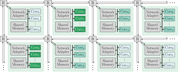
The ever-growing number of applications hosted in modern embedded systems introduces a high compute power demand which has given rise to the recent shift towards many-core architectures, e.g., Tilera TILE-Gx [4], Kalray MPPA-256 [9], and Intel SCC [23]. For scalability, a many-core architecture is often organized as a set of compute tiles interconnected via a Network-on-Chip (NoC), see Figure 1. Each compute tile comprises a Network Adapter (NA), a set of processing cores and peripherals such as memories which are interconnected via a set of buses. From a designer’s perspective, the large number and diversity of applications and their non-functional requirements, e.g., real-time constraints, in modern embedded systems introduces an immense system design complexity. This renders the integrated system design approach, in which the whole system is designed at once, impractical. Over the past decade, composable systems, e.g. [21], have emerged to address this issue. In a composable system, applications are temporally and/or spatially isolated from each other, enabling an incremental system design approach where each application is first developed and analyzed individually and then added to the system on demand [1].
Composability is particularly crucial for the development of dynamic many-core systems with variable workloads and hard real-time requirements. In such systems, several independent applications are executed simultaneously, each being launched and terminated on demand and independently from others, resulting in a dynamic mix of active applications and, thus, a dynamic availability of platform resources. Each running application may be exposed to a variable workload which corresponds to a dynamic compute power demand to, e.g., meet real-time constraints. Moreover, unforeseeable conditions, e.g., thermal hot spots and hardware faults, affect the execution of applications that are currently running on the affected regions of the platform. Reserving resources according to the worst-possible workload scenario often leads to an immense underutilization of system resources which is typically not acceptable due to cost concerns. To cope with such dynamics in both resource availability of the system and resource demand of applications, Hybrid Application Mapping (HAM) strategies have emerged recently [45, 50]. In HAM, each application is developed and analyzed individually using an off-line DSE which computes several deployment options, so-called mappings, of the application on the platform. The computed mappings are ensured to offer diverse resource demand and performance guarantees to address various run-time resource-availability and workload scenarios, respectively. The mappings computed for each application are then provided to a so-called run-time platform manager which launches each application on demand using a precomputed mapping that satisfies the on-line performance requirements of the application and the resource constraints of the platform. Moreover, if the mapping in use by a running application fails, e.g., due to thermal hot spots, resource faults, or a drastic workload change, the run-time manager switches the application to another precomputed mapping which conforms to the new conditions [37].
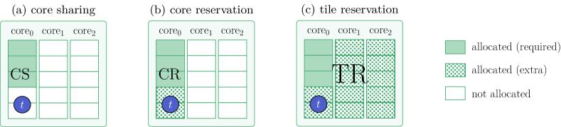
The off-line DSE used in HAM strategies employs compute-intensive optimization and verification techniques to find high-quality mappings that offer Pareto-optimal trade-offs w.r.t. multiple—oftentimes non-linear and conflicting—design objectives, e.g., resource usage, latency, energy, etc. To achieve predictability, the worst-case timing properties of each mapping are bounded based on the choice of allocated resources by deriving the worst-case timing interferences that may be imposed by other (concurrent) applications which share resources with the mapping under analysis [48]. During the DSE, however, an application is developed individually, and the characteristics of the potential concurrent applications are not available to be considered in the timing analysis. In order to regulate the maximum degree of timing interferences that may be imposed by other applications, temporal and spatial isolation techniques are employed which apply certain restrictions on the accessibility of resources used by the mapping under analysis to other applications that run concurrently. These restrictions are referred to as so-called inter-application isolation schemes. Figure 2 illustrates three major isolation schemes that are predominantly used in many-core systems to establish composability. In all three cases, an exemplary task is mapped to core0 of a 3-core tile. For the sake of brevity, only cores are depicted in the illustration of the tile. The compute power of each core is divided into 5 budgets of equal size. For a timely completion, requires a budget of 3 on core0. In the following, each isolation scheme is explained.
-
•
Core Sharing (CS). In the isolation scheme referred to as core sharing, illustrated in Figure 2a, only the 3 core budgets required for are allocated for the mapping. Hence, concurrent applications are temporally isolated from the current mapping on core0 and can use the 2 not-allocated budgets of core0, the whole budget of core1 and core2, and any other on-tile resource, e.g., memories and the NA. Core sharing is the least restrictive isolation scheme which merely depends on temporal isolation on all resources.
-
•
Core Reservation (CR). In the isolation scheme referred to as core reservation, illustrated in Figure 2b, core0 is allocated as a whole, regardless of the budget demand of . This realizes a spatial isolation from other applications on core0, eliminating interferences from them on core0 and resulting in an alleviated worst-case latency compared to core sharing. Note that interferences may still arise on other on-tile resources, e.g., memory buses used by , as applications are temporally isolated from each other on those resources.
-
•
Tile Reservation (TR). In the isolation scheme referred to as tile reservation, illustrated in Figure 2c, the compute tile is allocated as a whole, eliminating any interference from concurrent applications on any on-tile resource. This is the most restrictive isolation scheme which realizes a spatial isolation from concurrent applications at tile level and enables the largest reduction in the worst-case timing interferences imposed on .
| (a) Worst-Case Response Time assumed for – | |||
|---|---|---|---|
| isolation | WCRT() | WCRT() | WCRT() |
| scheme | |||
| TR | |||
| CR | |||
| CS | |||
| (b) Worst-Case Traversal Time assumed for | ||
|---|---|---|
| source | destination | WCTT() |
| isolation scheme | isolation scheme | |
| TR | TR | |
| TR | CR/CS | |
| CR/CS | TR | |
| CR/CS | CR/CS | |
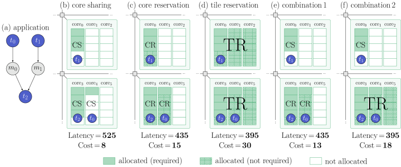
Noteworthy, sharing the NoC which interconnects the tiles can hardly be avoided [34]. Hence, applications are always temporally isolated from each other on the NoC. State-of-the-art composable many-core systems are designed based on a fixed isolation scheme that is uniformly applied to every core/tile of every mapping of every application in the system and is coupled with a timing analysis tailored to that specific isolation scheme to derive tight timing guarantees. The choice of isolation scheme highly impacts the resource usage and worst-case timing characteristics of the mappings. As an example, consider the application shown in Figure 3a and a mapping of it on two adjacent 3-core tiles illustrated in Figure 3b–f. For the sake of this motivational example, assume that the timing analysis of the tasks yields the qualitative Worst-Case Response Time (WCRT) values given in Table 1a under different isolation schemes. Likewise, the qualitative Worst-Case Traversal Time (WCTT) of message (communicated between the two tiles, from to ) is given in Table 1b for various combinations of isolation scheme on ’s source and destination cores/tiles. Message is implicitly communicated between and via the tile’s shared memories. In this example, applying core sharing exclusively, as illustrated in Figure 3b, offers the minimum allocation cost, i.e., 8 core budgets, at the expense of considerably high worst-case interferences on cores and other on-tile resources, resulting in an end-to-end application latency of 525 time units in the worst case. Applying core reservation exclusively, as depicted in Figure 3c, results in an elevated allocation cost of 15 budgets. It, however, eliminates core interferences which alleviates the worst-case application latency to 435 time units. Applying tile reservation exclusively, as depicted in Figure 3d, minimizes the worst-case application latency to 395 time units at the expense of a maximized allocation cost of 30 budgets.
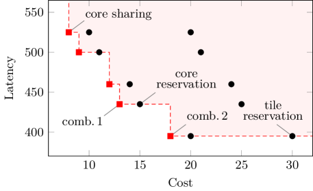
Motivation. A fixed isolation scheme that is always applied exclusively—which is the common practice in state-of-the-art composable many-core systems—heavily restricts the space of explored mappings and excludes numerous promising solutions where multiple isolation schemes are applied in combination. For instance, in the example above, considering arbitrary combinations of isolation schemes within one mapping enables 12 additional isolation scenarios, two of which are depicted in Figure 3e–f. In combination 1, core sharing is applied on core0 and core reservation is applied on core3 and core4, offering the same latency as the exclusive core-reservation scenario from Figure 3c, but at a lower cost. Likewise, combination 2 applies core sharing on core0 and tile reservation on the lower tile, outperforming the exclusive tile-reservation scenario from Figure 3d by offering the same latency at a considerably lower cost. Having evaluated all possible combinations of isolation scenarios, Figure 4 illustrates the obtained cost-latency trade-offs where Pareto-optimal trade-offs are designated by red squares, dominating the highlighted space above the red dashed line. The trade-offs corresponding to the scenarios in Figure 3 are labeled accordingly in Figure 4. As shown, nearly always, Pareto-optimal trade-offs are obtained only when multiple isolation schemes are applied in combination within one mapping. In Section 6, we experimentally verify this observation for realistic use cases as well.
Contribution. The example above demonstrates that using multiple isolation schemes in combination yields mappings of a better quality trade-off. Deriving safe bounds on the worst-case timing characteristics of such mappings, however, requires an isolation-aware timing analysis that can capture the impact of the isolation scheme of each core/tile on the worst-case timing behavior of tasks/messages affected by it and, hence, on the worst-case timing behavior of the application. On the one hand, existing timing analyses applicable to composable many-core systems are tailored to one fixed isolation scheme and cannot handle multiple isolation schemes in combination within one mapping. On the other hand, from an architectural point of view, many-core platforms are undergoing a transition from single-core tiles, e.g., in [4], to multi-core tiles, e.g., in [9]. This transition introduces new sources of timing interference within each tile, e.g., on shared memory buses, which must be accounted for to obtain safe timing guarantees. In the context of composable systems, there exist no timing analysis known to us which accounts for all sources of timing interference that may arise in a many-core platform with multi-core tiles (without applying restrictive spatial isolation schemes that eliminate on-tile inter-application interferences altogether). Provided with an isolation-aware timing analysis, the off-line DSE in HAM strategies can be extended to also explore the choices of isolation scheme for each core/tile within each investigated mapping to obtain solutions with a better quality trade-off. In this line, the paper at hand makes the following contributions in the context of composable many-core systems:
-
1.
We present an isolation-aware timing analysis which can handle arbitrary combinations of isolation schemes within one mapping and accounts for all timing interferences that may arise within a shared multi-core tile and on the NoC interconnecting tiles. It derives tight timing bounds by identifying and excluding interference scenarios that can never happen under the current combination of isolation schemes.
-
2.
We present an isolation-aware DSE which explores the choices of isolation scheme for each core/tile in each investigated mapping of the application under analysis and uses the proposed timing analysis for the scheduling and timing verification of the mappings.
For a variety of hard real-time applications and many-core platforms, we experimentally verify the advantage of the proposed isolation-aware exploration and timing analysis approach over existing fixed-isolation-scheme approaches in terms of the quality of obtained mappings.
Organization. The remainder of this paper is organized as follows. In Section 2, related work on timing analysis and DSE of multi-/many-core systems is reviewed. Section 3 presents the preliminaries and the system model for this work. The proposed isolation-aware DSE and timing analysis are presented in Sections 4 and 5, respectively. Experimental results are discussed in Section 6 before the paper is concluded in Section 7.
2 Related Work
Worst-case timing analysis of applications in multi-/many-core systems has long been conducted in two steps: First, a context-independent analysis is applied to bound the Worst-Case Execution Time (WCET) of each task in isolation, i.e., in absence of interferences. An overview of tools and methods for context-independent WCET analysis is provided in [51]. Following the context-independent analysis, an interference analysis is performed to bound the additional latencies that may be imposed on shared resources due to external interferences.
Multi-/many-core timing analyses predominantly focus on worst-case interference analysis based on the context-independent characteristics of each task and message. For instance, the analyses presented in [2, 6, 8, 15, 17, 40, 41, 46] bound the WCRT of tasks in a multi-core setup where several cores are connected to one or more memories over shared buses. In [2, 8], a framework for multi-core response time analysis is presented for a preemptive Fixed-Priority (FP) core scheduling policy coupled with multiple memory bus arbitration policies, e.g., Time-Division Multiplexing (TDM), Round-Robin (RR), and FP. Targeting mixed-criticality systems, [15, 17] analyze WCRT under a non-preemptive FP core scheduling policy and a RR memory bus arbitration. The authors of [40, 46] present response time analyses for non-preemptive FP core scheduling policy and a multi-level bus arbitration scheme which combines RR and FP policies. In [41], memory bus interference is bounded using an ILP-based timing analysis under a RR bus arbitration policy. The framework presented in [6], analyzes memory bus interference under a variety of arbitration policies, e.g., TDM and FP. Concerning the NoC, in [43] and [54] NoC transfer delays are analyzed under FP and RR link arbitration policies, respectively.
The works listed above consider—to some extent—non-preemptive and/or contention-oriented arbitration/scheduling policies, e.g., priority-based schemes, for which safe timing guarantees can be derived only if the whole set of applications accessing shared resources is known at the time of analysis. In a composable system, however, the mix of concurrently running applications that share some resources may not be known at design time. Hence, contention-oriented policies can be applied in a composable system only if each and every resource with such an arbitration scheme is exclusively used by one application. To realize this on state-of-the-art many-core platforms, each mapping computed for each application must (a) have a tile-reservation isolation scheme only, (b) be restricted within one tile only, and (c) not rely on inter-tile communications, e.g., I/O transfers. In practice, however, the small number of cores comprised within one tile [4, 23], on the one hand, and the high compute power demand of each application, on the other hand, necessitate the deployment of some applications over several compute tiles to meet their real-time requirements. For such applications, NoC links could—in theory—be exclusively reserved per application to enable the timing analysis of multi-tile mappings using NoC delay analyses, e.g. [54, 43]. In practice, however, sharing NoC links among applications can hardly be avoided [34].
Contention-free arbitration policies based on time slicing, e.g., TDM and Weighted Round-Robin (WRR), offer a practical approach for predictable inter-application resource sharing without violating composability. For instance, the authors of [48, 49] consider a NoC [22] with WRR link arbitration policy and analyze worst-case NoC delays based on the reserved link budget for each communication, independent of the other communication flows that may share the same links. For WCRT analysis, [48] considers a preemptive RR core scheduling policy which, however, restricts its scope of coverage to core interferences originating from within the application under analysis only. In [49], on the other hand, a WRR core scheduling policy is considered, and based on that, a response time analysis is presented which accounts also for core interferences that may be imposed by other (currently unknown) applications. Both [48, 49], however, consider single-core tiles and, hence, cannot capture NA and memory bus interferences that may arise in a multi-core tile, e.g., in [9, 23]. Contrarily, we present a timing analysis that captures also the NA and memory bus interferences in multi-core tiles.
From an isolation scheme point of view, existing multi-/many-core timing analyses are tailored to a fixed isolation scheme. For instance, the analyzes in [2, 6, 8, 15, 17, 40, 41, 46] are applicable only under tile-reservation isolation scheme. The analysis presented in [48] is applicable to systems with single-core tiles only and assumes tile-reservation isolation scheme. Authors in [49] consider single-core tiles and core-sharing isolation scheme. The timing analysis presented in this paper is the first timing analysis known to us which can handle arbitrary mixes of isolation schemes in combination within one mapping.
Application mapping in multi-/many-core systems is typically viewed as a multi-objective optimization problem and is known to be NP-hard [14]. Due to its immensely large space of possible mapping solutions, using exact optimization approaches, e.g., enumeration or (integer-)linear programming, to solve this NP-hard problem demands an extremely high computational effort and is prohibitively time-consuming, except for very small/simple problems. In this context, meta-heuristic optimization approaches, e.g., evolutionary/genetic algorithms [7, 13, 12], simulated annealing [27], and particle swarm optimization [25], enable a scalable optimization approach that can deliver high-quality solutions at a reasonable time- and computational effort. As a result, they have become the de facto standard approach for multi-objective application mapping optimization in multi-/many-core systems. For instance, in [33, 36, 48, 49], evolutionary/genetic algorithms are used for mapping optimization. In [16, 17], mapping optimization is realized using simulated annealing algorithms, while [42] adopts particle swarm optimization. The majority of existing works on mapping optimization in HAM methodologies employ population-based meta-heuristics, e.g., particle swarm optimization or evolutionary/genetic algorithms, to collect a so-called population of best mappings. During the Design Space Exploration (DSE), the optimizer follows the course of several iterations to generate new mappings and evaluate them w.r.t. the given set of design objectives, e.g., resource cost, timing, or energy. It collects a population of explored mappings which is updated per iteration to retain the best solutions found so far and is used for the generation of mappings in the next iteration. Like [33, 36, 48, 49], we employ a multi-objective evolutionary algorithm for mapping optimization.
To the best of our knowledge, existing DSE proposals on mapping optimization in the context of HAM strategies, e.g., [26, 33, 36, 47, 44, 48, 49, 53], consider a fixed isolation scheme that is applied exclusively to every resource (core or tile) of every explored mapping of every application. For instance, the DSE approaches in [36, 33, 53] assume a core-reservation isolation scheme. In [26, 44, 48], a tile-reservation isolation scheme is assumed. In [49], a core-sharing isolation scheme is assumed. The DSE proposed in this paper does not assume a globally-fixed isolation scheme. Instead, it explores the choices of isolation scheme per allocated resource within each explored mapping. This provides a fine-grained control over the degree of admitted inter-application interferences (which we analyze using the proposed timing analysis) and renders many mappings with promising quality trade-offs reachable to the DSE which are not reachable under a fixed isolation scheme.
3 Preliminaries
3.1 Mapping Optimization Problem Specification
Similar to any other optimization problem, the multi-/many-core mapping optimization problem requires a problem model which describes the space of possible solutions and the conditions that must be satisfied by a mapping to be regarded a valid solution. In this paper, we use the graph-based system model from [3]. This model represents the mapping optimization problem by a so-called specification which describes the entire design space and is used to generate different mapping solutions. The specification and each mapping generated based on that consist of an application graph, an architecture graph, and mapping edges connecting them, which will be introduced in Sections 3.1.2, 3.1.1 and 3.1.3.
3.1.1 Application Model
We consider periodic hard real-time applications. Each application is specified by an application graph where denotes the set of (processing) tasks, denotes the set of messages exchanged between tasks, and edges define data dependencies among tasks and messages, e.g., see Figure 5a. For each task , the execution period , the context-independent worst-case execution time on each mappable core , and the memory demand (maximum number of memory accesses) per execution iteration are known. For each message , the transfer period and the maximum payload size together with its corresponding memory demand (number of memory accesses for reading/writing from/to memory) are given.
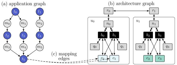
3.1.2 Architecture Model
We consider heterogeneous tiled many-core architectures composed of multi-core tiles interconnected by a NoC. The platform architecture is specified by an architecture graph , e.g., see Figure 5b. Here, denotes a NoC router, a NA, a memory bus, a processing core, and a shared memory (or memory bank) with an own memory bus, respectively. Edges represent bidirectional connections between these resources. Each represents a compute tile which comprises a set of cores and memories and a NA, thus, . Each memory (or memory bank) is accessible to cores and the NA on the same tile via a shared bus. Each NA consists of separate Transmitter (TX) and Receiver (RX) units with own ports to each memory bus. We assume many-core architectures without timing anomalies [39]. This enables a compositional analysis of execution, communication, and memory latency contributions which can be combined to derive globally safe timing guarantees.
Memory Model. We consider a No Remote Memory Access (NORMA) scheme which is commonly practiced in many-core systems to achieve scalability [32]. Under a NORMA scheme, the memories located on one tile are not accessible to resources located on other tiles, thus, data exchanges among different tiles are realized exclusively by means of explicit message passing between them. To achieve storage composability, (a) the on-tile memory space is partitioned, such that each core is given a dedicated storage space. Likewise, (b) shared caches are partitioned or disabled. In the same line, (c) the dedicated storage space of each core is dynamically partitioned among the tasks hosted by it. Finally, (d) each message is provided with a dedicated memory space in each tile where it is produced and/or consumed. To perform a memory access, the requestor must first attain the ownership of the shared bus associated with the target memory. We assume blocking and indivisible memory accesses, so that the processing progress on the requestor side is stalled during the memory operation. Each memory access is a single-word operation with a known maximum service time, eliminating burst/block operations. A requestor may perform several consecutive but non-overlapping single-word memory operations during its bus ownership interval.
NoC Model. We consider wormhole-switched NoCs with a credit-based virtual-channel flow control, for instance [22], to allow per-link bandwidth reservation and, thereby, to enable link sharing without violating composability. Under a wormhole-switched flow control, data packets are decomposed into control flow digits (flits) of fixed size which are then routed over the NoC independent from each other in a pipeline fashion [35]. The virtual-channel flow control [5] provides multiple buffers per physical link to enable transmission preemption and composable link sharing. The transmission progress of flits in each buffer of a router is controlled using so-called credits which reflect the availability of buffer space at the next router. This realizes a backpressure mechanism inherently.
Communication Model. Intra-tile communications, i.e., data exchanges within one tile, are realized through a dedicated space in the tile’s shared memories. Inter-tile communications, i.e., data exchanges between tiles, are realized by explicit message passing over the NoC. For the latter, after the data is written by the sender into the dedicated memory space, the TX reads the data, decomposes it into flits, and injects the flits into the NoC. The flits are then routed over the NoC toward the destination tile where the RX reconstructs the data from the flits and writes it into a dedicated memory space to be read by the receiver thereafter.
Resource Arbitration. Any hardware resource, e.g., cores, memory buses or the NoC, that can be shared among multiple applications is assumed to have an arbitration policy that is both predictable and composable. While (a) predictability enables formal worst-case timing analysis of each application, (b) composability ensures that worst-case timing bounds can be derived for each application merely based on the resource budgets reserved for it, without any knowledge about other applications that may run concurrently to it and share resources with it. This definition necessitates a contention-free arbitration policy for each and every resource that may be shared among applications. Time-Division Multiplexing (TDM) and Weighted Round-Robin (WRR) are well-established predictable and composable arbitration policies which serve as primary candidates for composable many-core systems [19, 21, 22]. Both TDM and WRR establish temporal isolation using time-triggered preemption, dividing the access to a resource into time slots of equal length that are periodically assigned to requestors which have reserved one or more slots on that resource. TDM is not work-conserving111In a work-conserving arbitration policy, time slots are assigned only to requestors with pending requests while idle slots, i.e., those without an access request, are skipped. This scheme results in a varying arbitration period and varying position of assigned slots for each requestor within one arbitration period. which leads to a poor average-case performance, making it an unattractive candidate for, e.g., systems hosting both real-time and best-effort applications [24]. Contrarily, WRR provides predictability and composability in a work-conserving fashion by skipping over idle slots. This enables a notable average-case performance improvement in favor of best-effort applications while allowing worst-case timing guarantees to be derived for real-time applications. We assume each shared resource has a preemptive time-triggered arbitration policy that follows similar principles as TDM and WRR.
3.1.3 Mapping Edges
In the specification of the mapping optimization problem, the application graph and the architecture graph are connected by mapping edges , e.g., see Figure 5c. Each mapping edge indicates that task can be executed on core .
3.2 Arbitration Tuple
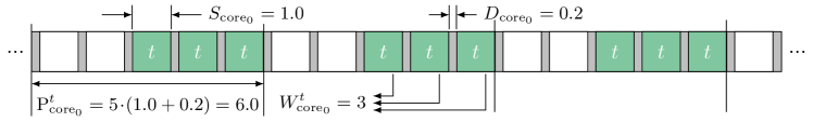
In this work, all parameters relevant for the worst-case timing analysis of a requestor on a resource, i.e., the budget reserved for it and the worst-case interference that can be imposed by other requestors, are compactly reflected by a so-called arbitration tuple: For each requestor of resource , the arbitration tuple is represented as where denotes the length of one arbitration slot of , denotes the number of periodic arbitration slots (weight) reserved for on , and denotes the worst-case arbitration period perceived by on . Given the arbitration tuple, one can deduce that has a periodic reserved time budget of on and, thus, experiences a worst-case wait time of per arbitration period . We exemplify the calculation of the arbitration tuple for task in Figure 2a under an arbitration policy with a slot length of , an arbitration delay of between consecutive slots222The arbitration delay denotes the latency of the arbiter for switching between consecutive arbitration slots. For instance, on a core, it corresponds to the context-switch overhead of the operating system., and an arbitration capacity of slots per period. Under such an arbitration policy, task with 3 reserved periodic slots perceives an arbitration weight of and a worst-case arbitration period of based on which the arbitration tuple is created as . This calculation is also illustrated in Figure 6. Note that, the arbiter delay is reflected in the calculation of arbitration period, rendering the arbitration tuple expressive of realistic resource arbiters in practice.
It may happen that the isolation scheme of a resource leads to one or more arbitration slots to be allocated by the mapping under analysis but not utilized. Given a work-conserving arbitration policy, e.g. WRR, in such cases we reduce the arbitration capacity of that resource to exclude those slots that are never utilized and, hence, are always skipped by the arbiter. For instance, in Figure 2b, core0 is allocated exclusively where only 3 slots are utilized by while the remaining 2 slots are never utilized. Thus, given a work-conserving arbitration policy, the arbitration period is guaranteed not to exceed , resulting in an adapted arbitration tuple of for on core0.
The proposed timing analysis presented in Section 5 takes the arbitration tuples as input and derives safe bounds on the worst-case timing characteristics of each task and message under the combination of applied isolation schemes. For the calculation of the arbitration tuples, the arbitration policy of each resource and its parameters, namely, arbitration slot length , arbitration delay , and arbitration capacity , are provided by the architecture, while both the isolation scheme of each resource and the number of slots reserved for each analyzed requestor are decided by the mapping optimizer during the DSE. We calculate arbitration tuples for the following requestors:
-
•
For each task , the arbitration tuple on core executing is calculated and denoted as .
-
•
For each inter-tile message , the arbitration tuple (a) on the TX tx injecting into the NoC, (b) on the NoC route (sequence of links) over which is routed, and (c) on the RX rx receiving from the NoC are calculated and denoted as , , and , respectively.
-
•
For each core that has at least one task mapped to it, the arbitration tuple on each on-tile memory bus is calculated and denoted as .
-
•
For each TX tx that routes at least one outbound message out of the tile, the arbitration tuple on each on-tile memory bus is calculated and denoted as .
-
•
For each RX rx that routes at least one incoming message into the tile, the arbitration tuple on each on-tile memory bus is calculated and denoted as .
4 Isolation-Aware Design Space Exploration (DSE)
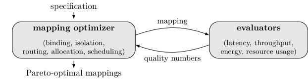
This section presents our isolation-aware DSE approach, illustrated in Figure 7. The DSE takes as input the specification of the mapping optimization problem comprising the application graph, the architecture graph, and mapping edges, and delivers a set of mappings that offer Pareto-optimal trade-offs w.r.t. a given set of design objectives, e.g., latency, throughput, energy, and resource usage. The DSE employs a mapping optimizer to explore the space of possible mappings of the application on the target architecture. The optimizer creates each mapping by conducting a series of binding, isolation, routing, allocation, and scheduling design decisions, elaborated later in Section 4.1. Once a mapping is generated, it is provided to a set of evaluators to assess the quality of the mapping w.r.t. the given design objectives. The proposed isolation-aware timing analysis, which will be presented in Section 5, is used here as an evaluator to derive safe bounds for timing-related design objectives, namely, latency and throughput. The optimizer uses an evolutionary algorithm which conducts several iterations to generate new mappings and collect a set of Pareto-optimal mappings.
The Pareto-optimal mappings will be used at run time to launch the application on demand by selecting a mapping that complies with the current real-time constraints of the application and resource availability of the system (restricted due to, e.g., other running applications). Since our timing analysis accounts for the worst-case interferences that may be imposed by any mix of (statically unknown) concurrent applications, the worst-case timing characteristics it provides for each mapping are guaranteed to hold regardless of the mix and deployment of other applications at run time. This allows the DSE to be performed for each application individually without any knowledge about the other applications in the system.
4.1 Mapping Creation
The creation of each mapping starts by making the binding and the isolation design decisions:
- •
- •
The creation of the mapping is completed by deriving the implications of binding and isolation decisions on message routing, resource allocation, and scheduling of tasks and message:
-
•
Routing. In this step, for each inter-tile message (i.e., a message communicated between two tasks which, according to the binding decisions, are bound to different tiles), a NoC route (sequence of links) is determined over which the message is transferred between the two tiles. Without loss of generality, we use the XY-routing algorithm [35].
-
•
Allocation. In this step, the processor budget required for the mapping is allocated according to the previously made binding and isolation decisions: If a task is bound onto any core of a reserved tile, the whole tile is allocated completely and, thus, none of the resources on that tile can be used by other applications (tile reservation). If a task is bound to a reserved core on a shared tile, that particular core is allocated completely while other resources on the tile can be used by other applications (core reservation). Finally, if a task is bound to a shared core on a shared tile, only the minimum budget required by that task will be allocated on that core while the remaining core budget can be used by other applications (core sharing). Any core and tile that does not correspond to one of the cases above is not allocated and, therefore, can be used by other applications. We also allocate the minimum budget required for each inter-tile message on NoC links that are part of the message’s route specified in the routing step.
-
•
Scheduling. We elaborate on the scheduling step in Section 4.2.
4.2 Isolation-Aware Scheduling
In the scheduling step, the arbitration tuples listed in Section 3.2 which are required for the timing analysis of the mapping are calculated. In what follows, we first calculate in Section 4.2.1 the resource budgets (arbitration weight) required for tasks and messages. Based on these weights, the arbitration tuples are then calculated in Section 4.2.2.
4.2.1 Resource Budget Calculation
To calculate the arbitration weight of each task/message on each respective resource , first the worst-case arbitration period for on is calculated (as presented in Section 3.2) based on ’s arbitration capacity and arbitration slot length which are provided by the architecture. Then, for each task bound to core , we start with an arbitration weight of and iteratively (I) construct the arbitration tuple and (II) use Equations 1, 2, 3 and 4 from Section 5 to determine ’s WCRT for the current arbitration weight . If the WCRT of exceeds its deadline given by the application, i.e., , we (III) increment by one and go back to step (I). Otherwise, the iterations are terminated and the current arbitration weight is considered for . Likewise, for each inter-tile message routed via TX unit tx, RX unit rx, and NoC route , we use Equations 5, 6, 7 and 8 from Section 5 to calculate the minimum arbitration weight such that ’s WCTT does not exceed its production period, i.e., .
After the weights are derived, we evaluate the overall weight demanded on each resource. If the weight demanded by all tasks mapped to a core exceed the core’s arbitration capacity, the mapping is considered as infeasible and is discarded. Likewise, if the weight demanded on a NoC link, a TX or a RX by messages routed over it exceeds its arbitration capacity, the mapping is considered as infeasible and discarded.
4.2.2 Arbitration Tuple Calculation
Given the arbitration weights of tasks and messages on their respective resources, calculated in Section 4.2.1, and the isolation scheme of each core/tile, the arbitration tuples for tasks and messages are calculated as follows. For each exclusively allocated core , first the arbitration capacity is reduced as to discard scheduling slots that are not utilized by the tasks mapped to it, and the arbitration period of each task mapped to it is refined accordingly as presented in Section 3.2. Then, the arbitration tuple is created for each task mapped to where the scheduling slot length is provided by the architecture. Likewise, for each exclusively allocated tile, first the arbitration capacity of the TX unit tx is reduced as to reflect only the arbitration slots reserved for the outbound messages of that tile within the current mapping. Then, the arbitration period of each outbound message on tx is refined, and the arbitration tuple is constructed. A similar procedure is followed for the incoming messages of the tile. Since the NoC is assumed to be shared, no reduction will be applied to the capacity of NoC links, and thus, no refinement is required for the calculation of the arbitration tuple of an inter-tile message on the links of its NoC route .
For each core , the arbitration tuple on each memory bus connected to it is calculated as follows. The bus arbitration slot length , the bus arbitration capacity , and the core arbitration weight on the bus are provided by the architecture. The arbitration period perceived by on bus is calculated according to the decided isolation scheme: If a tile-reservation isolation scheme is selected, the bus arbitration capacity is reduced to exclude the arbitration slots corresponding to idle cores (cores that do not host any tasks). Accordingly, the refined arbitration period is calculated as presented in Section 3.2. For each TX and RX, the arbitration tuples and on each memory bus connected to them is calculated similarly. Note that all arbitration capacity reductions discussed above are applied only in case of a work-conserving arbitration policy, e.g., WRR. Otherwise, the arbitration capacities remain unaffected.
5 Isolation-Aware Timing Analysis
This section presents the proposed timing analysis which formally bounds the WCRT of each task and the WCTT of each inter-tile message using the arbitration tuples calculated in the scheduling step. The timing analysis is performed compositionally [20], so that the worst-case timing behavior of each task/message is decomposed into several timing contributions on different resources which are analyzed separately and, then, are combined to obtain globally safe timing guarantees. The obtained task/message latency bounds are then used to bound the worst-case latency (makespan) and throughput of the mapping.
5.1 Worst-Case Response Time
The WCRT of a task denotes the worst-case time interval between its start time and completion time, subject to the worst-case timing interferences that may arise on shared resources due to the presence of interfering requests. In each iteration of its execution, a task reads its required data and input messages from the memory, performs its processing, and writes its output messages into the memory. In general, two sources of interference may occur here: (a) bus interferences when accessing memory and (b) preemption delays on the cores. Therefore, the WCRT of each task can be bounded as:
| (1) |
where denotes the worst-case execution time of on core in isolation, assuming a zero delay for bus and memory. denotes the memory demand (number of single-word memory accesses) of , and denotes the service time of memory over bus , i.e., the turnaround delay of a single-word memory access in absence of bus interferences. denotes the worst-case delay introduced due to interferences on bus over which memory is accessed. denotes the worst-case preemption delay imposed on ’s execution on . Here, and are provided by the application, is provided by the architecture, and and are derived as follows.
5.1.1 Memory Bus Interference
Given that task executed on core accesses memory over bus , we bound the worst-case memory bus interference based on the memory demand of , the service time of memory accessed over bus , and the arbitration tuple for core on bus . To this end, we first derive the maximum number of dedicated bus arbitration slots, denoted by , that may require for performing memory operations: On the one hand, can never exceed , since each bus arbitration slot is necessarily long enough to allow performing at least one single-word memory access, i.e., . On the other hand, can never exceed the maximum number of bus arbitration slots that may pass during ’s execution when performing its memory accesses in absence of bus interferences. Thus, can be bounded as:
| (2) |
In the worst case, the memory accesses of are distributed such that each of the required bus slots falls into a separate bus arbitration period. In each bus arbitration period, a worst-case wait time of may be imposed on ’s execution before acquires the bus ownership. Therefore, the overall bus interference can be bounded as:
| (3) |
In some cases, a memory access may be initiated so late that it cannot be completed before the end of the respective bus arbitration slot. To compensate for this misalignment, the arbitration delay of each bus is extended by the service time of its memory . This practice (a) allows late memory accesses to be completed before the next bus arbitration slot is assigned and, thereby, (b) eliminates memory interferences due to overlapping memory accesses from different bus masters in consecutive bus slots. Note that, if accesses multiple memories, the analysis above must be applied for each memory bus over which performs accesses to memory with a service time of .
5.1.2 Core Preemption Delay
We bound the worst-case preemption delay of task on core based on its arbitration tuple on , i.e., , and the arbitration tuple of on the bus over which accesses memory , i.e., . In each iteration of its execution, requires an overall dedicated processor time of on core to complete its processing and perform its memory accesses over the shared bus. In each scheduling period of , an overall processor time of is dedicated to and, hence, a worst-case periodic wait time of is imposed on ’s execution due to preemption. Thus, the overall preemption delay imposed on ’s execution can be bounded as:
| (4) |
where the first factor derives the maximum number of scheduling periods over which the execution of may span, and the second factor reflects the worst-case wait time imposed per scheduling period. Note that, also here, a memory access may be initiated so late that it cannot be completed before the end of the scheduling slot. To compensate for this misalignment, the context-switch latency of each core is extended by the maximum service time among all memories accessible to to allow an initiated memory access to be completed before the following context switch on .
5.2 Worst-Case Traversal Time
The WCTT of an inter-tile message denotes its worst-case transfer latency from the memory in which is stored on the source tile to the respective target memory on ’s destination tile. This transfer is realized in three steps: (I) the TX tx on the source tile reads from memory over bus , decomposes it into flits, and injects the flits into the NoC. (II) the flits are routed over ’s NoC route to the destination tile. Once arrived at the destination tile, (III) the RX rx reconstructs and writes it into ’s dedicated space in memory over bus . Therefore, the WCTT of message can be bounded as:
| (5) |
where , , and respectively denote the worst-case latency of the transfer steps (I)–(III) above which we analyze in the following.
5.2.1 TX/RX Latency
Reading message from memory over bus for injection into the NoC is subject to two sources of interference: (a) TX interference (as multiple outbound messages may be transmitted concurrently from the tile) and (b) bus interference (when TX accesses memory for reading ). We assume that, in each bus arbitration period, bus slots dedicated to TX tx are used for reading one message only, resulting in an equivalent tx slot length of one bus period, i.e., . To bound the TX latency , we first derive the maximum number of bus slots, denoted as , that can be required in the worst case for reading from memory : In each bus arbitration slot, a total of consecutive memory accesses can be initiated and completed. Hence, given ’s memory demand (number of memory accesses required for reading ), is calculated as:
| (6) |
Given , we use Equation 7 to bound the TX latency based on the arbitration tuple of tx on bus , i.e., , and the arbitration tuple of on tx, i.e., where as discussed above. The first summand in Equation 7 bounds the overall memory service time for the memory accesses required for reading from memory in absence of bus and TX interferences. The second summand calculates the worst-case bus interference imposed when reading : Here, the first factor gives the number of bus arbitration periods that may pass before acquiring all bus slots required for reading , and the second factor gives the worst-case wait time imposed per bus period. Finally, the third summand in Equation 7 calculates the worst-case TX interference: Here, the first factor calculates the number of tx arbitration periods involved in the transfer of , and the second factor gives the worst-case wait time per tx period. We use the same analysis to bound the RX latency, i.e., in Equation 5.
| (7) | ||||
5.2.2 NoC Latency
We bound the worst-case NoC routing latency of message over route based on the arbitration tuple of on the links in , i.e., , using Equation 8 adopted from [48]. Here, denotes the number of ’s flits which is calculated based on its payload size , gives the length of route in number of hops, denotes the length of one NoC clock cycle which also gives the length of one link arbitration slot (), and gives the latency of a NoC router in clock cycles. The first summand in Equation 8 derives the transfer latency of flits in absence of interferences on . The second summand bounds the worst-case interferences on : Here, the first factor gives the maximum number of link arbitration periods in which ’s flits may be stalled due to interfering flows, and the second factor gives the worst-case wait time per link arbitration period, see [48].
| (8) |
5.3 Worst-Case Throughput and Latency
Given the WCRT of each task , in short, , and the WCTT of each inter-tile message , in short, , the worst-case throughput of the mapping is calculated using Equation 9. Likewise, the worst-case application latency (makespan) is calculated using Equation 10 where denotes the set of all end-to-end paths in the application graph.
| (9) | |||
| (10) |
6 Experimental Results
This section presents the results of a series of experiments for a variety of applications and architectures to compare the performance of the proposed isolation-aware approach with existing fixed-isolation-scheme approaches w.r.t. the quality of delivered mappings.
6.1 Experiment Setup
Applications and Architectures. We use four real-time applications from the domains of networking (7 tasks, 9 messages), consumer (11 tasks, 12 messages), telecommunication (14 tasks, 20 messages), and automotive (18 tasks, 21 messages), provided by the Embedded System Synthesis Benchmarks Suite (E3S) [11]. For target platform, we use three heterogeneous many-core architectures with , , and tiles, respectively. Each architecture is composed of three tile types. Each tile comprises four homogeneous cores, a shared memory, a NA with separate TX and RX units, and a shared memory bus. Every shared resource has a WRR arbitration policy configured as follows: For each core, an arbitration capacity of , a slot length of us, and a context switch overhead of us is considered. On each bus, each bus master (TX, RX, and four cores) has an arbitration weight of , resulting in a bus arbitration capacity of . The length of each bus slot is set equal to the memory service time of 7 clock cycles. For NoC links, we consider an arbitration capacity of and a slot length ns. For each TX/RX, an arbitration capacity of and a slot length equal to the bus arbitration period is considered, cf. Section 5.2.1.
Design Objectives. We use three design objectives which are commonly considered in the DSE of predictable and composable many-core systems: (I) worst-case latency derived using the proposed timing analysis, (II) resource usage calculated (in number of cores) as the sum of time slots reserved on each core divided by core arbitration capacity , and (III) energy consumption, calculated based on the processor power parameters provided by [11] for each investigated benchmark application and the NoC/bus energy model from [52], assuming a link length of mm and a bus length of mm.
Design Space Exploration. To perform the DSE, we use the OpenDSE framework [38] and the NSGA-II [10] multi-objective evolutionary algorithm provided by the optimization framework Opt4J [30]. Each run of the DSE features 4,000 iterations with 25 mappings generated per iteration and a population size of 100 mappings. The results reported in this section are an average over 20 runs of the DSE for each application on each architecture.
Investigated Approaches. We compare the proposed isolation-aware DSE approach with the three major fixed-isolation-scheme DSE approaches, namely, core sharing, core reservation, and tile reservation. For each approach, the DSE delivers a set of mappings with Pareto-optimal trade-offs in the space of the three design objectives above. We compare the DSE approaches in terms of the quality of mappings they deliver.
Quality Metric. To compare the quality of mappings obtained by the investigated DSE approaches, we use the well-established metric [28] from the domain of multi-objective optimization, defined as follows: Let represent a set of Pareto-optimal mappings obtained by an optimization approach in the space of design objectives to be minimized. Let represent a reference set containing the true Pareto-optimal mappings for the optimization problem in question. To assess the quality of mappings in w.r.t. , provides a unary indicator calculated as:
| (11) |
where and denote the quality of mappings and , respectively, w.r.t. design objective . A smaller value for indicates a smaller distance between the mappings in and those in the reference set w.r.t. the design objectives which, in turn, denotes a higher quality of mappings in . For our following experiments, the reference set is constructed by collecting the mappings obtained by the four approaches under analysis in one set.
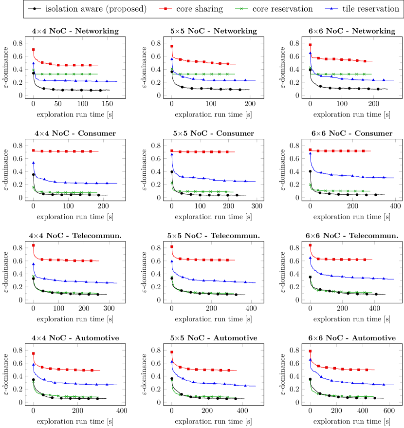
6.2 Result Discussion
Figure 8 illustrates, for each benchmark application on each many-core architecture, the indicator for the proposed approach and the three fixed-isolation-scheme approaches across their exploration run time. The plots in each row correspond to the same application, and the plots in each column correspond to the same architecture. In general, the quality of mappings collected by each approach improves as the exploration progresses, resulting in a decrease in the indicator of each approach throughout the course of its optimization iterations. Also, the exploration time of each approaches grows with the application size (compare the plots in one column) and architecture size (compare the plots in one row). The results illustrated in Figure 8 uniformly verify that (a) the proposed approach always outperforms the approaches with a fixed isolation scheme, irrespective of the choice of application and architecture, which is indicated by its lower indicator at the end of its exploration. Moreover, (b) the proposed approach exhibits an exploration run time within the same range as the other approaches and, hence, does not impact the scalability of the optimization approach adversely. Among the other approaches, core reservation generally performs better than core sharing and tile reservation for most of cases. Core sharing exhibits the worst quality of solutions for all applications and architectures. Considering all 12 combinations of applications and architectures, the proposed isolation-aware approach achieves an improvement of up to (compared with the core-sharing approach) with an average improvement of over the three fixed-isolation-scheme approaches.
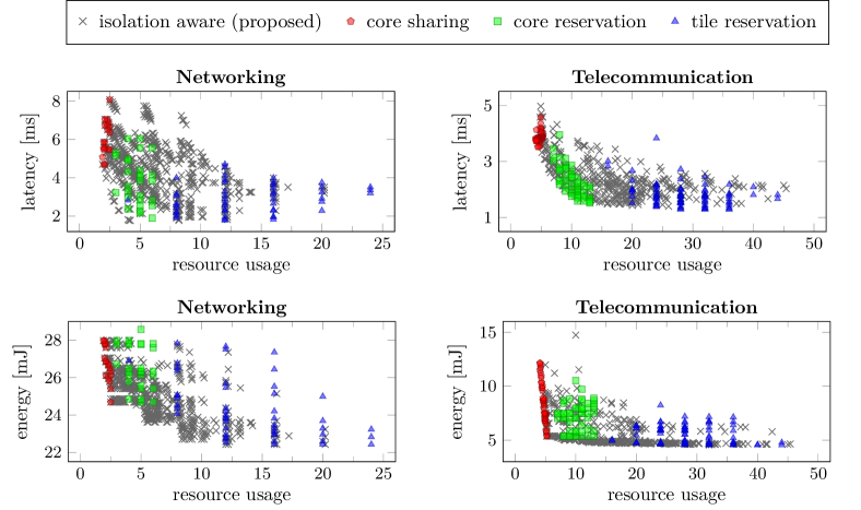
To reason about these quality differences, we investigate the distribution of the mappings delivered by each DSE approach in the 3D objective space. Figure 9 illustrates this using two 2D projections of the objective space for two exemplary applications on the architecture. Similar distributions are obtained for other applications and architectures. For each application (column), the x-axes in both projections denote resource usage while the y-axes denote worst-case latency (top) and energy consumption (bottom). As illustrated, solutions delivered by the core-sharing approach exhibit low resource usage, as this approach allocates a minimal resource budget, just enough to meet the deadlines of tasks/messages. This, however, implies a high worst-case inter-application interference and, thus, considerably high worst-case latency and energy consumption. The tile-reservation approach, on the other hand, allocates compute tiles exclusively (thus, higher resource usage) which eliminates all on-tile inter-application interferences (thus, lower latency and energy). When considering all objectives together, both of these approaches need a large scaling factor to compensate for their inferior objective values, explaining their poor (high) indices in Figure 8. A compromise between these approaches is achieved by core reservation which restricts the exclusive allocation of resources to cores, leading to a moderate trade-off between resource usage, latency, and energy consumption and, thus, a better (lower) index.
The fixed isolation scheme of the approaches above excludes large parts of the actual solution space and, thus, restricts their coverage of the objective space to a considerably smaller sub-region. Contrary to them, the proposed approach covers and extends beyond the solution space of these approaches as it explores the isolation schemes in combination within each mapping, also reflected by the wide spread of its solutions in Figure 9. As a result, it can find solutions of higher quality and, thus, outperforms the other approaches as confirmed by its lower index in Figure 8 for all investigated applications and architectures.
7 Conclusion
Applications in composable many-core systems are typically developed with the assumption of a fixed inter-application isolation scheme which restricts the resource allocation policy of the applications and, therefore, their quality trade-off w.r.t. resource usage and worst-case timing. To lift this restriction, we have proposed (a) an isolation-aware DSE which explores the isolation schemes per allocated core/tile within each mapping and (b) an isolation-aware timing analysis to formally bound the worst-case timing properties of each explored mapping. For a variety of hard real-time applications and many-core architectures, we have experimentally demonstrated the advantage of the proposed approach over existing fixed-isolation-scheme approaches w.r.t. the quality of the delivered solutions in terms of resource usage, worst-case latency, and energy consumption.
References
- [1] Benny Akesson, Anca Molnos, Andreas Hansson, Jude Ambrose Angelo, and Kees Goossens. Composability and predictability for independent application development, verification, and execution. In Multiprocessor System-on-Chip, pages 25–56. Springer, 2011.
- [2] Sebastian Altmeyer, Robert I Davis, Leandro Indrusiak, Claire Maiza, Vincent Nelis, and Jan Reineke. A generic and compositional framework for multicore response time analysis. In Proceedings of the Conference on Real Time Networks and Systems (RTNS), pages 129–138. ACM, 2015.
- [3] Tobias Blickle, Jürgen Teich, and Lothar Thiele. System-level synthesis using evolutionary algorithms. Design Automation for Embedded Systems, 3(1):23–58, 1998.
- [4] Tilera Corporation. Tile processor architecture overview for the TILE-Gx series, 2012.
- [5] William J Dally. Virtual-channel flow control. IEEE Transactions on Parallel and Distributed systems, 3(2):194–205, 1992.
- [6] Dakshina Dasari, Vincent Nelis, and Benny Akesson. A framework for memory contention analysis in multi-core platforms. Real-Time Systems, 52(3):272–322, 2016.
- [7] Lawrence Davis. Handbook of genetic algorithms. VNR computer library. Van Nostrand Reinhold, 1991.
- [8] Robert I Davis, Sebastian Altmeyer, Leandro S Indrusiak, Claire Maiza, Vincent Nelis, and Jan Reineke. An extensible framework for multicore response time analysis. Real-Time Systems, pages 1–55, 2017.
- [9] Benoît Dupont de Dinechin, Renaud Ayrignac, Pierre-Edouard Beaucamps, Patrice Couvert, Benoit Ganne, Pierre Guironnet de Massas, François Jacquet, Samuel Jones, Nicolas Morey Chaisemartin, Frédéric Riss, et al. A clustered manycore processor architecture for embedded and accelerated applications. In Proceedings of High Performance Extreme Computing Conference (HPEC), pages 1–6. IEEE, 2013.
- [10] Kalyanmoy Deb, Amrit Pratap, Sameer Agarwal, and T Meyarivan. A fast and elitist multiobjective genetic algorithm: NSGA-II. IEEE Transactions on Evolutionary Computation, 6(2):182–197, 2002.
- [11] Robert Dick. Embedded system synthesis benchmarks suite (E3S), 2010. URL: http://ziyang.eecs.umich.edu/~dickrp/e3sdd/.
- [12] Carlos M. Fonseca and Peter J. Fleming. Genetic algorithms for multiobjective optimization: Formulation, discussion and generalization. In Proceedings of the International Conference on Genetic Algorithms, pages 416–423. Morgan Kaufmann Publishers Inc., 1993.
- [13] Carlos M Fonseca and Peter J Fleming. An overview of evolutionary algorithms in multiobjective optimization. Evolutionary computation, 3(1):1–16, 1995.
- [14] Michael R Garey and David S Johnson. A guide to the theory of NP-completeness. Computers and Intractability, pages 37–79, 1990.
- [15] Georgia Giannopoulou, Kai Lampka, Nikolay Stoimenov, and Lothar Thiele. Timed model checking with abstractions: Towards worst-case response time analysis in resource-sharing manycore systems. In Proceedings of the International Conference on Embedded Software, pages 63–72. ACM, 2012.
- [16] Georgia Giannopoulou, Nikolay Stoimenov, Pengcheng Huang, and Lothar Thiele. Scheduling of mixed-criticality applications on resource-sharing multicore systems. In Proceedings of the International Conference on Embedded Software, page 17. ACM, 2013.
- [17] Georgia Giannopoulou, Nikolay Stoimenov, Pengcheng Huang, Lothar Thiele, and Benoît Dupont de Dinechin. Mixed-criticality scheduling on cluster-based manycores with shared communication and storage resources. Real-Time Systems, 52(4):399–449, 2016.
- [18] Michael Glaß, Jürgen Teich, Martin Lukasiewycz, and Felix Reimann. Hybrid optimization techniques for system-level design space exploration. In Handbook of Hardware/Software Codesign, volume 1, pages 217–246. Springer, 2017.
- [19] Kees Goossens, Arnaldo Azevedo, Karthik Chandrasekar, Manil Dev Gomony, Sven Goossens, Martijn Koedam, Yonghui Li, Davit Mirzoyan, Anca Molnos, Ashkan Beyranvand Nejad, et al. Virtual execution platforms for mixed-time-criticality systems: the CompSOC architecture and design flow. ACM SIGBED Review, 10(3):23–34, 2013.
- [20] Sebastian Hahn, Jan Reineke, and Reinhard Wilhelm. Towards compositionality in execution time analysis: definition and challenges. ACM SIGBED Review, 12(1):28–36, 2015.
- [21] Andreas Hansson, Kees Goossens, Marco Bekooij, and Jos Huisken. CoMPSoC: A template for composable and predictable multi-processor system on chips. ACM Transactions on Design Automation of Electronic Systems (TODAES), 14(1):2, 2009.
- [22] Jan Heisswolf, Ralf König, Martin Kupper, and Jürgen Becker. Providing multiple hard latency and throughput guarantees for packet switching networks on chip. Computers & Electrical Engineering, 39(8):2603–2622, 2013.
- [23] Jason Howard, Saurabh Dighe, Yatin Hoskote, Sriram Vangal, David Finan, Gregory Ruhl, David Jenkins, Howard Wilson, Nitin Borkar, Gerhard Schrom, et al. A 48-core IA-32 message-passing processor with DVFS in 45nm CMOS. In International Solid-State Circuits Conference Digest of Technical Papers (ISSCC), pages 108–109. IEEE, 2010.
- [24] Timon Kelter, Tim Harde, Peter Marwedel, and Heiko Falk. Evaluation of resource arbitration methods for multi-core real-time systems. In Proceedings of the workshop on Worst-Case Execution Time Analysis (WCET). Schloss Dagstuhl-Leibniz-Zentrum für Informatik, 2013.
- [25] James Kennedy. Particle swarm optimization. Encyclopedia of Machine Learning, pages 760–766, 2010.
- [26] Pham Nam Khanh, Amit Kumar Singh, Akash Kumar, and Khin Mi Mi Aung. Incorporating energy and throughput awareness in design space exploration and run-time mapping for heterogeneous MPSoCs. In Proceedings of the Euromicro Conference on Digital System Design (DSD), pages 513–521. IEEE, 2013.
- [27] Scott Kirkpatrick, C Daniel Gelatt, and Mario P Vecchi. Optimization by simulated annealing. science, 220(4598):671–680, 1983.
- [28] Marco Laumanns, Lothar Thiele, Kalyanmoy Deb, and Eckart Zitzler. Combining convergence and diversity in evolutionary multiobjective optimization. Evolutionary Computation, 10(3):263–282, 2002.
- [29] Martin Lukasiewycz, Michael Glaß, Christian Haubelt, and Jürgen Teich. SAT-decoding in evolutionary algorithms for discrete constrained optimization problems. In Proceedings of the IEEE Congress onEvolutionary Computation, pages 935–942. IEEE, 2007.
- [30] Martin Lukasiewycz, Michael Glaß, Felix Reimann, and Jürgen Teich. Opt4J: a modular framework for meta-heuristic optimization. In Proceedings of the Conference on Genetic and Evolutionary Computation (GECCO), pages 1723–1730. ACM, 2011.
- [31] Martin Lukasiewycz, Shanker Shreejith, and Suhaib A Fahmy. System simulation and optimization using reconfigurable hardware. In International Symposium on Integrated Circuits (ISIC), pages 468–471, 2014.
- [32] Guilherme Madalozzo, Liana Duenha, Rodolfo Azevedo, and Fernando G Moraes. Scalability evaluation in many-core systems due to the memory organization. In Proceedings of the International Conference on Electronics, Circuits and Systems (ICECS), pages 396–399. IEEE, 2016.
- [33] Giovanni Mariani, Prabhat Avasare, Geert Vanmeerbeeck, Chantal Ykman-Couvreur, Gianluca Palermo, Cristina Silvano, and Vittorio Zaccaria. An industrial design space exploration framework for supporting run-time resource management on multi-core systems. In Proceedings of the Design, Automation and Test in Europe Conference and Exhibition (DATE), pages 196–201, 2010.
- [34] Tulika Mitra, Jürgen Teich, and Lothar Thiele. Time-critical systems design: A survey. IEEE Design & Test, 35(2):8–26, 2018.
- [35] Lionel M Ni and Philip K McKinley. A survey of wormhole routing techniques in direct networks. Computer, 26(2):62–76, 1993.
- [36] Roberta Piscitelli and Andy D Pimentel. Design space pruning through hybrid analysis in system-level design space exploration. In Proceedings of the Conference on Design, Automation and Test in Europe Conference and Exhibition (DATE), pages 781–786. IEEE, 2012.
- [37] Behnaz Pourmohseni, Stefan Wildermann, Michael Glaß, and Jürgen Teich. Hard real-time application mapping reconfiguration for NoC-based many-core systems. Real-Time Systems, pages 1–37, 2019.
- [38] Felix Reimann, Martin Lukasiewycz, Michael Glaß, and Fedor Smirnov. OpenDSE – open design space exploration framework, 2018. URL: http://opendse.sourceforge.net/.
- [39] Jan Reineke, Björn Wachter, Stefan Thesing, Reinhard Wilhelm, Ilia Polian, Jochen Eisinger, and Bernd Becker. A definition and classification of timing anomalies. In Proceedings of the International Workshop on Worst-Case Execution Time Analysis (WCET). Schloss Dagstuhl-Leibniz-Zentrum für Informatik, 2006.
- [40] Hamza Rihani, Matthieu Moy, Claire Maiza, Robert I Davis, and Sebastian Altmeyer. Response time analysis of synchronous data flow programs on a many-core processor. In Proceedings of the conference on Real-Time Networks and Systems (RTNS), pages 67–76. ACM, 2016.
- [41] Benjamin Rouxel, Steven Derrien, and Isabelle Puaut. Tightening contention delays while scheduling parallel applications on multi-core architectures. ACM Transactions on Embedded Computing Systems (TECS), 16(5s):164, 2017.
- [42] Pradip Kumar Sahu, Tapan Shah, Kanchan Manna, and Santanu Chattopadhyay. Application mapping onto mesh-based network-on-chip using discrete particle swarm optimization. IEEE Transactions on Very Large Scale Integration (VLSI) Systems, 22(2):300–312, 2014.
- [43] Z. Shi and A. Burns. Real-time communication analysis for on-chip networks with wormhole switching. In International Symposium on Networks-on-Chip (NOCS), pages 161–170, 2008.
- [44] Amit Kumar Singh, Akash Kumar, and Thambipillai Srikanthan. Accelerating throughput-aware runtime mapping for heterogeneous mpsocs. ACM Transaction on Design Automation of Electronic Systems (TODAES), 18(1):9:1–9:29, 2013.
- [45] Amit Kumar Singh, Muhammad Shafique, Akash Kumar, and Jörg Henkel. Mapping on multi/many-core systems: survey of current and emerging trends. In Proceedings of the Design Automation Conference (DAC), pages 1–10, 2013.
- [46] Stefanos Skalistis and Alena Simalatsar. Worst-case execution time analysis for many-core architectures with NoC. In International Conference on Formal Modeling and Analysis of Timed Systems, pages 211–227. Springer, 2016.
- [47] Stefanos Skalistis and Alena Simalatsar. Near-optimal deployment of dataflow applications on many-core platforms with real-time guarantees. In Proceedings of the Design, Automation and Test in Europe Conference and Exhibition (DATE), pages 752–757. IEEE, 2017.
- [48] Andreas Weichslgartner, Deepak Gangadharan, Stefan Wildermann, Michael Glaß, and Jürgen Teich. DAARM: Design-time application analysis and run-time mapping for predictable execution in many-core systems. In Proceedings of the International Conference on Hardware/Software Codesign and System Synthesis (CODES+ISSS), pages 1–10, 2014.
- [49] Andreas Weichslgartner, Stefan Wildermann, Deepak Gangadharan, Michael Glaß, and Jürgen Teich. A design-time/run-time application mapping methodology for predictable execution time in MPSoCs. ACM Transactions on Embedded Computing Systems (TECS), 2018.
- [50] Andreas Weichslgartner, Stefan Wildermann, Michael Glaß, and Jürgen Teich. Invasive Computing for mapping parallel programs to many-core architectures. Springer, 2018.
- [51] Reinhard Wilhelm, Jakob Engblom, Andreas Ermedahl, Niklas Holsti, Stephan Thesing, David Whalley, Guillem Bernat, Christian Ferdinand, Reinhold Heckmann, Tulika Mitra, et al. The worst-case execution-time problem-overview of methods and survey of tools. ACM Transactions on Embedded Computing Systems (TECS), 7(3):36, 2008.
- [52] Pascal T Wolkotte, Gerard JM Smit, Nikolay Kavaldjiev, Jens E Becker, and Jürgen Becker. Energy model of networks-on-chip and a bus. In Proceedings of the International Symposium on System-on-Chip (SoC), pages 82–85, 2005.
- [53] Chantal Ykman-Couvreur, Prabhat Avasare, Giovanni Mariani, Gianluca Palermo, Cristina Silvano, and Vittorio Zaccaria. Linking run-time resource management of embedded multi-core platforms with automated design-time exploration. IET Computers and Digital Techniques, 5(2):123–135, 2011.
- [54] Jia Zhan, Nikolay Stoimenov, Jin Ouyang, Lothar Thiele, Vijaykrishnan Narayanan, and Yuan Xie. Designing energy-efficient NoC for real-time embedded systems through slack optimization. In Proceedings of the Design Automation Conference (DAC), pages 1–6. IEEE, 2013.