Design of the Magnet System of the Neutron Decay Facility PERC
Abstract
The PERC (Proton and Electron Radiation Channel) facility is currently under construction at the research reactor FRM II, Garching. It will serve as an intense and clean source of electrons and protons from neutron beta decay for precision studies. It aims to contribute to the determination of the Cabibbo-Kobayashi-Maskawa quark-mixing element from neutron decay data and to search for new physics via new effective couplings.
PERC’s central component is a long superconducting magnet system. It hosts an long decay region in a uniform field. An additional high-field region selects the phase space of electrons and protons which can reach the detectors and largely improves systematic uncertainties. We discuss the design of the magnet system and the resulting properties of the magnetic field.
1 Introduction
Free neutron -decay provides a clean platform for precision searches for physics beyond the standard model Dub11 ; Gon19 . This is enabled by the absence of nuclear structure effects and small and well-known radiative corrections111We note that the common radiative corrections changed recently Sen18 .. Within the standard model, free neutron decay is completely described by only three parameters which have to be determined experimentally. These are the ratio of axial- and vector- coupling constants , the element of the Cabibbo-Kobayashi-Maskawa quark mixing matrix, and the Fermi coupling constant . The latter is known with very high precision from muon decay Web11 . is most precisely determined from a measurement of the parity-violating beta asymmetry Mun13 ; Bro18 ; Mae18 . In combination with a measurement of the neutron lifetime , the matrix element can be determined. The precision reached is competitive with single measurements entering the most precise determination from superallowed nuclear decays and the results are in agreement Mae18 ; Dub19 . Within the framework of effective field theories Bha12 ; Cir13 ; Gon19 , neutron beta decay experiments test for deviations from the theory of the standard model, i.e. hypothetical scalar and tensor interactions, as well as right handed currents. A comparison of the experimentally determined to lattice QCD results limits right handed couplings Cha18 .
Observables in neutron decay are the lifetime , (angular) correlation coefficients (see Jac57 ; Dub11 ), and the energy spectra of the decay protons and electrons. There are currently strong world-wide efforts to measure the beta asymmetry Dub08 ; Bro18 ; Mae18 , the neutrino asymmetry Dub08 ; Bro17 , the proton asymmetry Roi18b ; Dub08 , the electron-neutrino correlation Dar17 ; Bae13 ; Kon09 , the Fierz interference term Hic17 ; Sau18 ; Bae13 ; Bro17 ; Dub08 and several coefficients related to the transverse electron polarisation Bod16 . A non-zero Fierz interference term would be of special interest as it would directly imply novel scalar or tensor interactions. More experiments are proposed at the upcoming European Spallation Source (ESS) using a new intense beam line for particle physics Sol18 .
In this manuscript we discuss the facility PERC (Proton and Electron Radiation Channel) Dub08 ; Kon12 , which is currently under construction at the new MEPHISTO beam site MEPHISTO at the research reactor FRM II, Garching, Germany. The aim of PERC is to provide a clean, bright and versatile source of neutron decay products (electrons and protons) to enable measurements which improve on the results of Perkeo II Mun13 by at least an order of magnitude using specialised secondary spectrometers.
The concept of PERC, as well as a study of systematic effects is described in detail in Dub08 . Its main features are a large active volume of inside a neutron guide to observe the decay of free cold neutrons and a magnetic filter which limits the phase space of electrons and protons and strongly improves systematics. Together this enables distortion-free measurements on the level of Dub08 .
Developments by the collaboration that are important for PERC include non-depolarising supermirror neutron guides Reb14 , precision neutron polarimetry Zimmer99 ; Klauser12 ; Klauser13 , electron and proton detection systems based on existing techniques Raf16 ; Roi18b and novel concepts Wang13 ; Kon15 , calibration sources for proton spectroscopy Vir17 and calibration techniques for electron detection Roi18a , refined data analysis and understanding of the detector response Roi18b ; Sau18 ; Mae18 ; Roi19 , and the transport of particles in the magnetic field Dub14 .
In this paper we focus on the design of PERC’s magnet system and give insight on its optimisation. An in depth discussion of the design decisions can be found in Wang13dis ; Zie15 and the design was briefly introduced in Kon12 . The field optimisation was partially performed using the commercial package CST Studio CST , the RADIA Chu98 add-on to Wolfram Mathematica, as well as the magfield3 code developed by F. GlÃck Glu11 .
2 The PERC magnet system
The main component of PERC is a long superconducting magnet system. The strong magnetic field defines a quantisation axis and guides the neutron spin in case of measurements with a polarised beam. Electrons and protons are guided by the field towards detector systems at the rear end and are separated from the cold neutron beam in a curved magnetic field section.
PERC will be installed at the new MEPHISTO beamline for cold neutrons currently under construction at the FRM II. The beamline will provide several optional features such as a wavelength selector, chopper, polariser and spin flipper to allow for different measurement modes. The projected neutron capture flux density is .
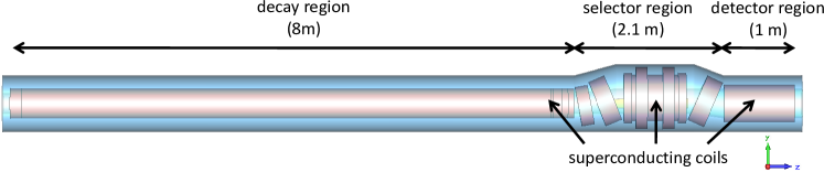
The PERC magnet consists of three different sections as illustrated in Fig. 1: the decay region, the selector region which contains the magnetic filter and separates charged decay products from the neutron beam, and the detector section which contains detector systems or serves to transport the electrons and protons to specialised spectrometers downstream.
The decay region consists of an long superconducting solenoid that features a homogeneous magnetic field of up to . A non-depolarising supermirror neutron guide is located inside the warm bore of the solenoid and contains the actual decay volume. In order not to alter measurements of the beta and proton asymmetry significantly, this guide must preserve the neutron polarisation at the level per bounce and will hence be based on copper and titanium Reb14 . While only a small fraction of the neutrons decay within the guide, the majority is absorbed by the neutron beamstop, which is located in the subsequent selector region. The charged decay products follow the magnetic field lines towards both ends of the solenoid.
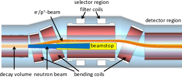
In the selector region, three tilted coils create a curved magnetic field of maximum strength . This decouples the -beam from the neutron beam as illustrated in Fig. 2. Behind the neutron beamstop, the are guided back to the central axis. This is different to the original design described in Dub08 . It enables varying the field over a wide range without drastically affecting the particle trajectories and to implement an efficient “two pinhole” shielding scheme to suppress background created by the internal guide or neutron beam components upstream of PERC. Since the -beam in the detector region is on-axis with the magnet system, it can be coupled to additional magnet systems downstream.
The field in the selector region acts as a magnetic mirror. This allows to filter electrons and protons according to their angle of emission relative to the magnetic field direction, with the critical angle in the adiabatic limit only being dependent on the magnetic field:
| (1) |
where is the magnetic field at the location of the decay. Hence for and .
After the selector region, the field strength decreases to . For a typical value of , the maximum pitch angle of electrons and protons hence decreases to
| (2) |
This reduces backscatter effects from the detector by a factor of compared to Perkeo.
Different detector systems specialised on measurements of certain observables will be attached here in order to detect electrons or protons, or both simultaneously. An example of such a spectrometer is the momentum spectrometer NoMoS currently under development Wang13 ; Kon15 .
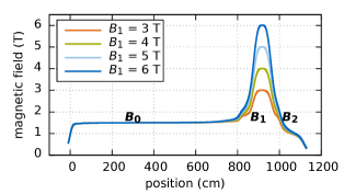
Fig. 3 shows the magnetic field strength along the central field line. The effect of the magnetic filter can be varied by adjusting both and such that to either optimise for a specific measurement or to test the corresponding systematic effect. This extends the range envisaged in Dub08 .
Beta asymmetry
An important quantity to be measured with PERC is the beta asymmetry parameter in neutron decay. This parity violating observable describes an asymmetry in the direction of the momentum of the decay electron with respect to the neutron spin:
| (3) |
where is the neutron polarisation and is the electron energy. With PERC, an experimental asymmetry will be determined from electron count rates for the two opposite directions of the neutron beam polarisation:
| (4) |
where refers to the average neutron polarisation pointing to the detector and pointing away. This method has been successfully applied in previous measurements of the beta asymmetry, including the currently most precise determination of Mae18 . However, in these measurements no magnetic filter has been applied. Taking into account the new PERC feature of phase space filtering, the relation between the experimental asymmetry and the beta asymmetry can be written as:
| (5) |
where we have neglected theoretical corrections. Note that the phase space filtering increases the measured asymmetry, while lowering the rate of detected events.
3 Magnets and Field Properties
The magnet system of PERC consists of different superconducting solenoids, not counting correction windings. The most complex magnet assembly is the selector which alone consists of solenoids, see Fig. 2. Four individual power supplies allow to tune the fields in the long solenoid , the selector region and the detector region separately. The selector region is driven by two power supplies: one creates the base field and the other drives the split pair configuration (filter coils) to increase the field up to , see Fig. 2.222The technical reason for the fourth power supply is the use of different types of superconducting wire in the decay and selector regions.
3.1 Decay region
The long solenoid generates the magnetic field in the decay volume. Additional windings or small gaps in the winding package at both ends of the solenoid improve the magnetic field uniformity.
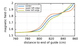
The magnetic field of PERC must not have local minima where charged particles may be trapped temporarily. Within the decay volume the resulting unpredictable losses and delays would hamper any high precision measurement. But even outside the neutron beam such traps could be filled by rest gas interaction leading to undesired background. Fig. 4 shows the field strength along field lines originating in the center and at the edges of the neutron guide (with a cross section of ) for the critical configuration, i.e. with the minimum field change between the decay and selector regions. Field minima are absent.
In order to avoid decay particles staying within the decay region for extended periods of time, the field in the decay region is not completely uniform, but slightly increases towards the downstream end, see Fig. 3. This inhomogeneity of within the decay volume influences the emission angle selection for the . Thus the measured asymmetry changes according to Eq. (5). This effect is shown in Fig. 5. We note that the field uniformity perpendicular to the beam is much better, so only the direction along the beam axis counts.
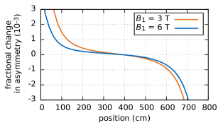
For measurements with a continuous beam, this correction to the asymmetry would have to be integrated over the decay volume taking the neutron density into account. This would also include the strong contributions (and related uncertainties) at the ends of the long solenoid. A pulsed neutron beam can be used to minimise and control this effect as shown in Refs. Mae09 ; Mae18 leading to a effect only.
3.2 Selector region
The purpose of the selector region is two-fold: it separates the -beam from the neutron beam and provides the high field region for the phase space selection. The filter coils allow to change the magnetic field strength from to in order to vary the filter effect. This split-pair design ensures a very good field uniformity over the entire field range. A pair of correction coils at both ends of the selector improves the uniformity of and eliminates minima between the selector and bending coils.
The -beam is decoupled from the neutron beam using two tilted bending coils and guided to the selector coil assembly, as shown in Fig. 2. The region from the end of the neutron guide to the point where the -beam is separated from the neutrons is situated in an increasing magnetic field. This leads to large corrections with sizable uncertainties to an asymmetry measurement with a continuous beam. Thus the decoupling distance is designed to be as short as reasonably possible, while any local field minima must be avoided. Assuming an neutron supermirror inside PERC, the neutron beam will have a divergence of at a mean wavelength of . The resulting decoupling distance then is .
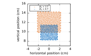
In order to accommodate the neutron beamstop with its radiation shielding in the selector, the separation distance between the -beam and the neutron beam centers is required to be larger than . As a consequence of the asymmetry in the magnet layout and as a compromise to the complexity of the set-up, this beam separation is allowed to vary with a change in the field strength. Fig. 6 shows the simulated -beam distribution in the center plane of the selector for and . The -beam shifts by as much as . We note that this requires the -diaphragm, which is located there to limit edge effects, to be adjustable in size and position, see Dub08 for details.
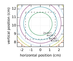
In order to guarantee the required field uniformity in the center plane on the level, the magnet design has to match this shift with in the -beam trajectory. The point of the field minimum in this plane must shift accordingly using the additional filter coils. Fig. 7 shows the relative deviation of the field over the -beam cross-section. The maximum effect is for and for .
The -transport has to fulfill the adiabatic condition , with the field gradient over one helical pitch. Within the decay volume is negligibly small. Only in a small region at the end of the filter region reaches a still tolerable value of . At the rear end of PERC increases due to the drop of the magnetic field. We note that detector systems are either placed inside the detector region or the adiabatic transport must be ensured by additional connecting magnet systems.
4 Technical Aspects
A number of technical aspects influence the magnet design. For the production of PERC copper strands enclosing the superconducting wire with a rectangular cross section are used (wire-in-channel). Due to the helical winding scheme, the effective length of a solenoid is about one turn shorter than the coil former. Also the coils require enough space between them for the necessary mechanical supports. In the following we discuss some selected technical aspects.
4.1 Quench safety
We use a superconducting wire based on Niobium Titanium alloy (NbTi). It consists of a bunch of twisted filaments with diameters of or embedded in a copper matrix. This round wire is soldered in a rectangular copper strand TDR .
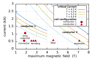
The quenching of a superconductor wire is a function of the temperature , the local magnetic field , the current density , and other factors like mechanical disturbances. Empirical formulae for the critical current density can for example be found in Lub83 ; Mai85 ; Bot00 . The highest magnetic field at the wire of the magnet is and occurs at the inner surface of the selector coil. Fig. 8 shows the critical current as a function of and , and the configuration of the different PERC solenoids. We note that the actual measured critical current of the wires exceed the nominal specification by to EAS15 .
4.2 Magnetic shielding
In order to contain its high magnetic field, PERC will be equipped with a magnetic field return made of iron and steel. Four long iron bars are mounted alongside the magnet. At the high-field region, the field return is enforced by steel plates. As a result, the magnetic field strength decreases to the cardiac pacemaker limit of within from the central magnet axis.
The non-linear material of the shielding also influences the magnetic field inside PERC. The maximal change of the field is 3.7% at the ends of PERC. The field in the center of PERC changes by less than 0.5%. These changes do not induce local field minima. The homogeneity in the -beam cross-section in the selector coil is not influenced significantly Wang13dis .
5 Conclusion, Outlook
With the design discussed in this paper the magnet system of PERC fulfils all criteria outlined in the instrument proposal which also includes an analysis of systematics Dub08 . In addition, the range of possible field configurations , , has been extended considerably, albeit at a lower nominal field due to superconductor constraints.
The improved separator design allows for excellent shielding of the main detectors downstream from beam-related background. It also ensures stable particle trajectories and the possibility to couple secondary spectrometers to PERC. The drawback of this scheme is that it is more difficult to monitor the neutron polarisation behind PERC since detector systems and beamstop have to be removed first. Using polarised 3He target cells, neutron polarisation can be measured at the level required for PERC Klauser13 ; Klauser16 .
It is foreseen that PERC will be equipped with an active particle dump at the upstream end to detect particles reflected by the magnet filter or backscattered from the downstream detector Zie15 . In addition, this enables a time-of-flight technique for detector calibration Roi18a .
The technical design of the PERC magnet system is described in TDR . The magnet system is currently in production and the delivery is expected in spring 2020.
The authors gratefully acknowledge the excellent support by the FRM II and the engineers and workshops at the various institutions. We thank in particular K. Lehmann (FRM), M. Horvath (ATI), and B. Windelband and his team (HD). We thank F. GlÃck for providing his magnetic field codes. This work is supported by the Priority Programme SPP 1491 of German Research Foundation (DFG), contracts No. MA4944/1-1, MA4944/1-2, AB128/5-2 HE2308/9-1, SCH2708/1-1, SO1058/1-1, SO1058/2-1 and ZI816/1-1, the Austrian Science Fund (FWF), contracts No. I 528-N20, I 534-N20 and P 26636-N20, the University of Heidelberg, the FRM II, and the DFG cluster of excellence Origin and Structure of the Universe.
References
- (1) D. Dubbers, M.G. Schmidt, Rev. Mod. Phys. 83, 1111 (2011)
- (2) M. González-Alonso, O. Naviliat-Cuncic, N. Severijns, Progr. Part. Nucl. Phys. 104, 165 (2019)
- (3) C.Y. Seng, M. Gorchtein, H.H. Patel, M.J. Ramsey-Musolf, Phys. Rev. Lett. 121, 241804 (2018)
- (4) D.M. Webber, V. Tishchenko, Q. Peng, S. Battu, R.M. Carey, D.B. Chitwood, J. Crnkovic, P.T. Debevec, S. Dhamija, W. Earle et al. (MuLan Collaboration), Phys. Rev. Lett. 106, 041803 (2011)
- (5) D. Mund, B. MÃrkisch, M. Deissenroth, J. Krempel, M. Schumann, H. Abele, A. Petoukhov, T. Soldner, Phys. Rev. Lett. 110, 172502 (2013)
- (6) M.A.P. Brown, E.B. Dees, E. Adamek, B. Allgeier, M. Blatnik, T.J. Bowles, L.J. Broussard, R. Carr, S. Clayton, C. Cude-Woods et al. (UCNA Collaboration), Phys. Rev. C 97, 035505 (2018)
- (7) B. MÃrkisch, H. Mest, H. Saul, W. X., H. Abele, D. Dubbers, M. Klopf, A. Petoukhov, C. Roick, T. Soldner et al., Phys. Rev. Lett. (2019), accepted, 1812.04666
- (8) D. Dubbers, H. Saul, B. MÃrkisch, T. Soldner, H. Abele, Phys. Lett. B791, 6 (2019), 1812.00626
- (9) T. Bhattacharya, V. Cirigliano, S.D. Cohen, A. Filipuzzi, M. González-Alonso, M.L. Graesser, R. Gupta, H.W. Lin, Phys. Rev. D 85, 054512 (2012)
- (10) V. Cirigliano, S. Gardner, B.R. Holstein, Progr. Part. Nucl. Phys. 71, 93 (2013)
- (11) C.C. Chang, A.N. Nicholson, E. Rinaldi, E. Berkowitz, N. Garron, D.A. Brantley, H. Monge-Camacho, C.J. Monahan, C. Bouchard, M.A. Clark et al., Nature 558, 91 (2018)
- (12) J.D. Jackson, S.B. Treiman, H.W. Wyld, Phys. Rev. 106, 517 (1957)
- (13) D. Dubbers, H. Abele, S. Baeßler, B. Märkisch, M. Schumann, T. Soldner, O. Zimmer, Nucl. Instr. Meth. A 596, 238 (2008)
- (14) L. Broussard, B. Zeck, E. Adamek, S. BaeÃler, N. Birge, M. Blatnik, J. Bowman, A. Brandt, M. Brown, J. Burkhart et al., Nucl. Instr. Meth. A 849, 83 (2017)
- (15) C. Roick, Ph.D. thesis, Technische UniversitÃt MÃnchen (2018)
- (16) G. Darius, W.A. Byron, C.R. DeAngelis, M.T. Hassan, F.E. Wietfeldt, B. Collett, G.L. Jones, M.S. Dewey, M.P. Mendenhall, J.S. Nico et al., Phys. Rev. Lett. 119, 042502 (2017)
- (17) S. BaeÃler, R. Alarcon, L.P. Alonzi, S. Balascuta, L. BarrÃn-Palos, J.D. Bowman, M.A. Bychkov, J. Byrne, J.R. Calarco, T. Chupp et al., AIP Conf. Proc. 1560, 114 (2013)
- (18) G. Konrad, F. Ayala Guardia, S. BaeÃler, M. Borg, F. GlÃck, W. Heil, I. Konorov, K. Leung, R. MuÃoz Horta, M. Simson et al., Nucl. Phys. A 827, 529c (2009)
- (19) K.P. Hickerson, X. Sun, Y. Bagdasarova, D. Bravo-BerguÃo, L.J. Broussard, M.A.P. Brown, R. Carr, S. Currie, X. Ding, B.W. Filippone et al. (UCNA Collaboration), Phys. Rev. C 96, 042501 (2017)
- (20) H. Saul, Ph.D. thesis, Technische UniversitÃt Wien, Technische UniversitÃt MÃnchen (2018)
- (21) K. Bodek, Acta Phys. Polon. B47, 349 (2016)
- (22) T. Soldner, H. Abele, G. Konrad, B. MÃrkisch, F.M. Piegsa, U. Schmidt, C. Theroine, P. Torres Sánchez, ANNI - A pulsed cold neutron beam facility for particle physics at the ESS, in International Workshop on Particle Physics at Neutron Sources 2018 (PPNS 2018) Grenoble, France, May 24-26, 2018 (2018), 1811.11692
- (23) G. Konrad, H. Abele, M. Beck, C. Drescher, D. Dubbers, J. Erhart, H. Fillunger, C. GÃsselsberger, W. Heil, M. Horvath et al., J. Phys: Conf. Ser. 340, 012048 (2012)
- (24) FRM II, Garching, MEPHISTO, Facility for particle physics with cold neutrons, DOI: 10.17815/jlsrf-1-48
- (25) N. Rebrova, Ph.D. thesis, UniversitÃt Heidelberg (2014), DOI: 10.11588/heidok.00017029
- (26) O. Zimmer, T.M. MÃller, W. Heil, H. Humblot, P. Hautle, Phys. Lett. B 455, 62 (1999)
- (27) C. Klauser, J. Chastagnier, D. Jullien, A. Petoukhov, T. Soldner, J. Phys: Conf. Ser. 340, 012011 (2012)
- (28) C. Klauser, T. Bigault, N. Rebrova, T. Soldner, Phys. Proc. 42, 99 (2013), 9th International Conference on Polarised Neutrons in Condensed Matter Investigations
- (29) L. Raffelt, Ph.D. thesis, UniversitÃt Heidelberg (2016), DOI: 10.11588/heidok.00022095
- (30) X. Wang, G. Konrad, H. Abele, Nucl. Instr. Meth. A 701, 254 (2013)
- (31) G. Konrad, PoS EPS-HEP2015, 592 (2015)
- (32) R. Virot, Ph.D. thesis, Università Grenoble Alpes (2017), https://tel.archives-ouvertes.fr/tel-01731369
- (33) C. Roick, D. Dubbers, B. Märkisch, H. Saul, U. Schmidt, Phys. Rev. C 97, 035502 (2018)
- (34) C. Roick, H. Saul, H. Abele, B. Märkisch, Undetected Electron Backscattering in Perkeo III, in International Workshop on Particle Physics at Neutron Sources 2018 (PPNS 2018) Grenoble, France, May 24-26, 2018 (2019)
- (35) D. Dubbers, L. Raffelt, B. MÃrkisch, F. Friedl, H. Abele, Nucl. Instr. Meth. A 763, 112 (2014)
- (36) X. Wang, Ph.D. thesis, Technical University of Munich (2013), http://mediatum.ub.tum.de?id=112129
- (37) C. Ziener, Ph.D. thesis, UniversitÃt Heidelberg (2015), DOI: 10.11588/heidok.00017949
- (38) CST Computer Simulation Technology AG
- (39) O. Chubar, P. Elleaume, J. Chavanne, J. Synchrotron Rad. 5, 481 (1998)
- (40) F. Glück, Prog. Electromagn. Res. B 32, 351 (2011)
- (41) B. MÃrkisch, H. Abele, D. Dubbers, F. Friedl, A. Kaplan, H. Mest, M. Schumann, T. Soldner, D. Wilkin, Nucl. Instr. Meth. A 611, 216 (2009)
- (42) Babcock-Noell GmbH, Tech. Rep. S911051-ED–BNG-00004 (2017)
- (43) M. Lubell, IEEE. T. Magn. 19, 754 (1983)
- (44) R. Maix, D. SalathÃ, Practical Scaling Formulas for the Determination of the Critical currents in NbTi Superconductors, in Proceedings at the 9th International Conference on Magnet Technology (ZÃrich, Switzerland, 1985)
- (45) L. Bottura, IEEE Trans. Appl. Supercond. 10, 1054 (2000)
- (46) Bruker EAS GmbH, Tech. rep. (2015)
- (47) C. Klauser, T. Bigault, P. BÃni, P. Courtois, A. Devishvili, N. Rebrova, M. Schneider, T. Soldner, Nucl. Inst. & Meth. A 840, 181 (2016)