Interface-engineered hole doping in Sr2IrO4/LaNiO3 heterostructure
Abstract
The relativistic Mott insulator Sr2IrO4 driven by large spin-orbit interaction is known for the = 1/2 antiferromagnetic state which closely resembles the electronic structure of parent compounds of superconducting cuprates. Here, we report the realization of hole-doped Sr2IrO4 by means of interfacial charge transfer in Sr2IrO4/LaNiO3 heterostructures. X-ray photoelectron spectroscopy on Ir 4f edge along with the X-ray absorption spectroscopy at Ni edge confirmed that 5 electrons from Ir sites are transferred onto Ni sites, leading to markedly electronic reconstruction at the interface. Although the Sr2IrO4/LaNiO3 heterostructure remains non-metallic, we reveal that the transport behavior is no longer described by the Mott variable range hopping mode, but by the Efros-Shklovskii model. These findings highlight a powerful utility of interfaces to realize emerging electronic states of the Ruddlesden-Popper phases of Ir-based oxides.
Keywords: complex oxide heterostructure, X-ray absorption spectroscopy, layered-Iridates,
1 Introduction
Transition metal oxides (TMOs) with a partially filled d-shell often host strongly correlated carriers and exhibit unique physical properties due to the intertwined lattice, charge, orbital and spin degrees of freedom.[1] In 3 TMOs, since the crystal field (CF) splitting is approximately an order of magnitude larger than the intrinsic spin-orbit coupling (SOC) , the effect of SOC is usually neglected in the determination of the ground state. However, in 4 and 5 TMOs, the enhanced strength of becomes comparable to . As the outcome of the competing interactions dominated by SOC, a large number of unusual quantum states including topological insulators[2], quantum spin liquids [3], Weyl semimetals [4], and Kitaev materials[5] have been recently predicted. In this category, Sr2IrO4 is one of the prototypical examples of materials known as the relativistic Mott insulators. Naively, due to the spatially extended orbitals and the decreased on-site Coulomb repulsion, a metallic ground state is naturally expected in this compound. Contrary to the expectation, Sr2IrO4 is antiferromagnetic insulator. [6] To explain the discrepancy, the proposed physical picture suggests that the degeneracy of the Ir 5 levels is first lifted by the CF splitting while the strong SOC further splits the t2g bands into fully occupied J = 3/2 subbands and a half-filled J = 1/2 subband. Additionally, the on-site Coulomb interaction further splits the J = 1/2 band into an upper Hubbard band (UHB) and a lower Hubbard band (LHB), realizing the spin-orbit assisted Mott ground state. [7, 8]
Based on this picture, a strong similarity between Sr2IrO4 and the parent componds of high Tc cuprates has been highlighted in various experiments. Specifically, Sr2IrO4 crystallizes in the K2NiF4-type structure and is an antiferromagnetic insulator with the magnetic transition temperature Tc 240 K. [8, 9] Resonant inelastic x-ray scattering experiments reveales that the magnetic excitations of Sr2IrO4 on the square lattice can be well described within an antiferromagnetic Heisenberg model[10] akin to the parent compounds of cuprates. Furthermore, it has been proposed that upon hole and electron doping, this material can potentially host a high Tc superconducting state.[11, 12, 13]
Recent measurements have provided many evidences for the possible superconducting hidden phase in Sr2IrO4. [14, 15, 16, 17, 18] Despite the early encouraging progress, to date, there is no report on superconducting behavior in doped Sr2IrO4.[19, 20, 21, 22] Naturally, one of the possible reasons could be that the degree of doping has not reached the critical value for the superconducting state to emerge. However, there has been chemical doping reaching the level of the theory prediction (around or more), but the superconducting phase is yet to be found.[13, 15, 16, 21, 22] Considering that the high chemical doping level might, on the other hand, also affect many crytallographic properties of the system, searching for alternative ways to realize such a high doping in Sr2IrO4 without atoms replacement might be vital to identify the hidden superconducting phase with iridates.
In this letter, we report on creating high hole doping of Sr2IrO4 by virtue of engineering a heteroepitaxial interface composed of Sr2IrO4 and LaNiO3 ultra-thin layers. Scanning transmission electron microscopy (STEM) and X-ray reflectivity (XRR) results confirm high quality, good crystallinity, well-formed interfaces and expected periodicity of the heterostructures. Photoelectron spectroscopy data (XPS) and X-ray absorption spectra (XAS) reveal distinct charge modulations at the interface, leading to electron transfer from Ir to Ni sites across the interfaces. X-ray linear dichroism studies have revealed that the charge redistribution lifts the orbital degeneration in Ni2+, and therefore created the Ni2+ ( = 1) and Ir5+ ( = 0) electronic configurations at the interface. Although the heterostructure remains insulating, we found that the transport behavior is no longer described by the Mott variable range hopping model, but by the Efros-Shklovskii model.
2 EXPERIMENTAL SECTION
High-quality Sr2IrO4/LaNiO3 superlattices were epitaxially synthesized on (001) oriented SrTiO3 substrate by pulsed laser deposition (KrF excimer laser, =248 nm) with substrate temperature of 690 ∘C and oxygen pressure of 10 mTorr. Targets were ablated at the laser frequency of 2Hz and fluency of 1 - 4 J/cm2. The layer-by-layer growth was monitored by in-situ high-pressure reflection high-energy election diffraction (RHEED).
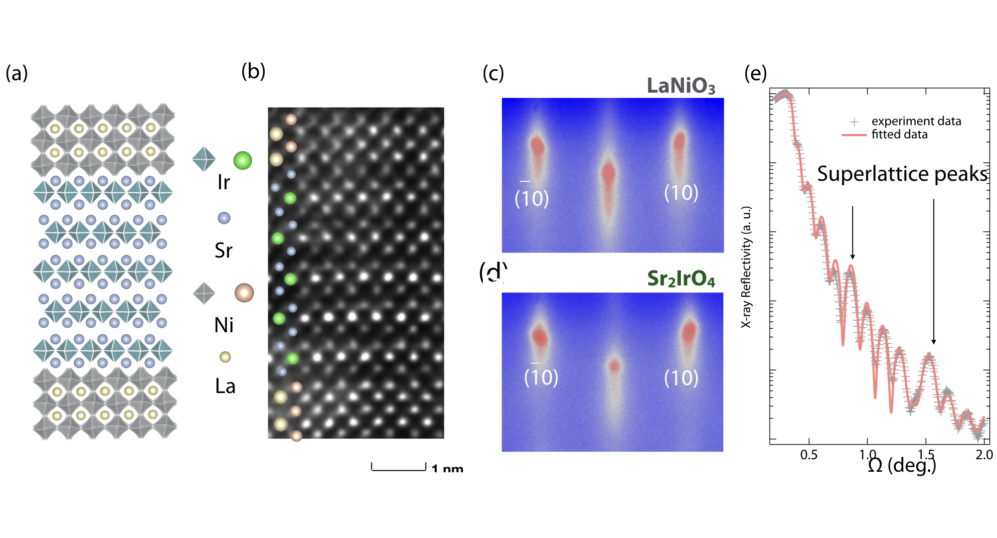
The crystallinity and epitaxy of the sample has been verified by several methods. First, the samples have been investigated by STEM (see Fig. 1 (b)). As seen, within the LaNiO3 layers, the La distribution shows a typical perovskite structure. In the Sr2IrO4, two atomic planes of SrO are observed between each layer of IrO2 in according with the expected layered-perovskite structure. Sharp interfaces between Sr2IrO4 and LaNiO3 resulting from the layer-by-layer structure of the heterostructure are also evident from the STEM images. The STEM result is in a good agreement with the in-situ RHEED measurements for both Sr2IrO4 and LaNiO3 layers (see Fig. 1(c) and (d)). Furthermore, the XRR measurement confirms the superlattice structure and allow to estimate the total film thickness, as shown in Fig. 1 (e). The total thickness obtained from the fitting result is 30.768 ( 0.13) nm while the thickness of each individual layer is 6.221 (0.014) nm.
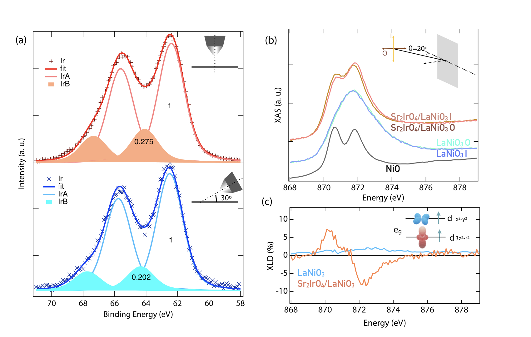
Next, to understand the electronic structure associated with the Ir charge state at the Sr2IrO4/LaNiO3 interfaces, we carried out a set of XPS measurements with different detection angle. Figure 2 (a) shows the Ir 4 core level spectrum of the superlattice. From the direct fitting of the spectral shape, one can see that the Ir 4f envelope contains two doublet contributions. Specifically, the main doublet appearing at binding energy 62.3 eV and 65.6 eV represents the Ir4+ states which are expected for the stoichiometric undoped system (IrA). There is also another doublet contribution (IrB) with binding energy close to 64 eV and 67.3 eV, which can result from the formation of Ir5+, or accompanied satellite peaks of Ir4+[23, 24, 25, 26]. In order to prove the existence of Ir5+, angle-resolved XPS was conducted with two different detection angles. By changing the detection geometry, the XPS can show signals with different probing depth. If the IrB doublet is purely the satellite peaks, the relative intensity to the main doublet IrA should be a fixed value at different detection angle. However, there is a clear variation of IrB relative intensity as the detector is changed from normal to grazing position. This observation confirms the presence of Ir5+ in Sr2IrO4 layers at the interfacial region.
Next, we turn to investigate the charge distribution on Ni in the vicinity of the interface by XAS at the Ni L2 edge. As seen in a typical scan depicted in Fig. 2 (b) there is a clear double peak structure at the L2 edge in the superlattice with either horizontal- or vertical-polarized X-rays (orange curve). This observation is in sharp contrast to the reference LaNiO3 sample with pure Ni3+, confirming the presence of Ni2+ due to the charge transfer. By fitting the XAS result of the superlattices with respect to the pure Ni3+ and Ni2+ reference samples, the contribution of Ni2+ is 70%, which indicates a large amount charge transfer happening at the interfaces.
Soft x-ray absorption with linearly polarized light or X-ray linear dichroism (XLD) allows for further insight in to the orbital occupation of the Ni2+. Experimentally, the XLD is defined as the difference between absorption spectra measured with horizontally polarized light (O) where the polarization points out of the plane, and in-plane polarized light (I) with polarization in the plane, or IO-II. As shown in Fig. 2 (c), in the undoped LaNiO3 layer (before charge transfer) Ni3+ is in 3d7 state with the band fully occupied and band occupied with one electron. After electron transfer nickel ions shift the Ni valence state down towards Ni2+ with two electrons occupying the eg orbitals. In our experimental setup, out-of-plane polarized X-rays probe the empty out-of-plane orbitals () while in-plane polarized light senses primarily orbital character. The observed XLD signal can be attributed to the difference in orbital occupation of vs. orbitals. From the XAS data shown in Fig. 2 (b) and the XLD data shown in Fig. 2 (c), one can see that the absorption of photons with horizontal polarization (O) is shifted lower in energy relative to photons with vertical polarization (I) shifted to a higher energy. This result implies that the interface imposes a sub-band splitting of 0.1 eV which lowers the Ni and lifts the orbital states (see Fig. 2 (c) inset). Further, the integrated XLD area is close to zero suggesting that both orbitals are equally occupied.[27, 28, 29] In short, the XAS/XLD measurements confirms the electrons transferred from Ir to Ni sites. This leads to (i) formation of Ni2+ with high spin =1 configuration at the interface, and (ii) split of the Ni band into two sub-bands with predominant orbital and orbital character.
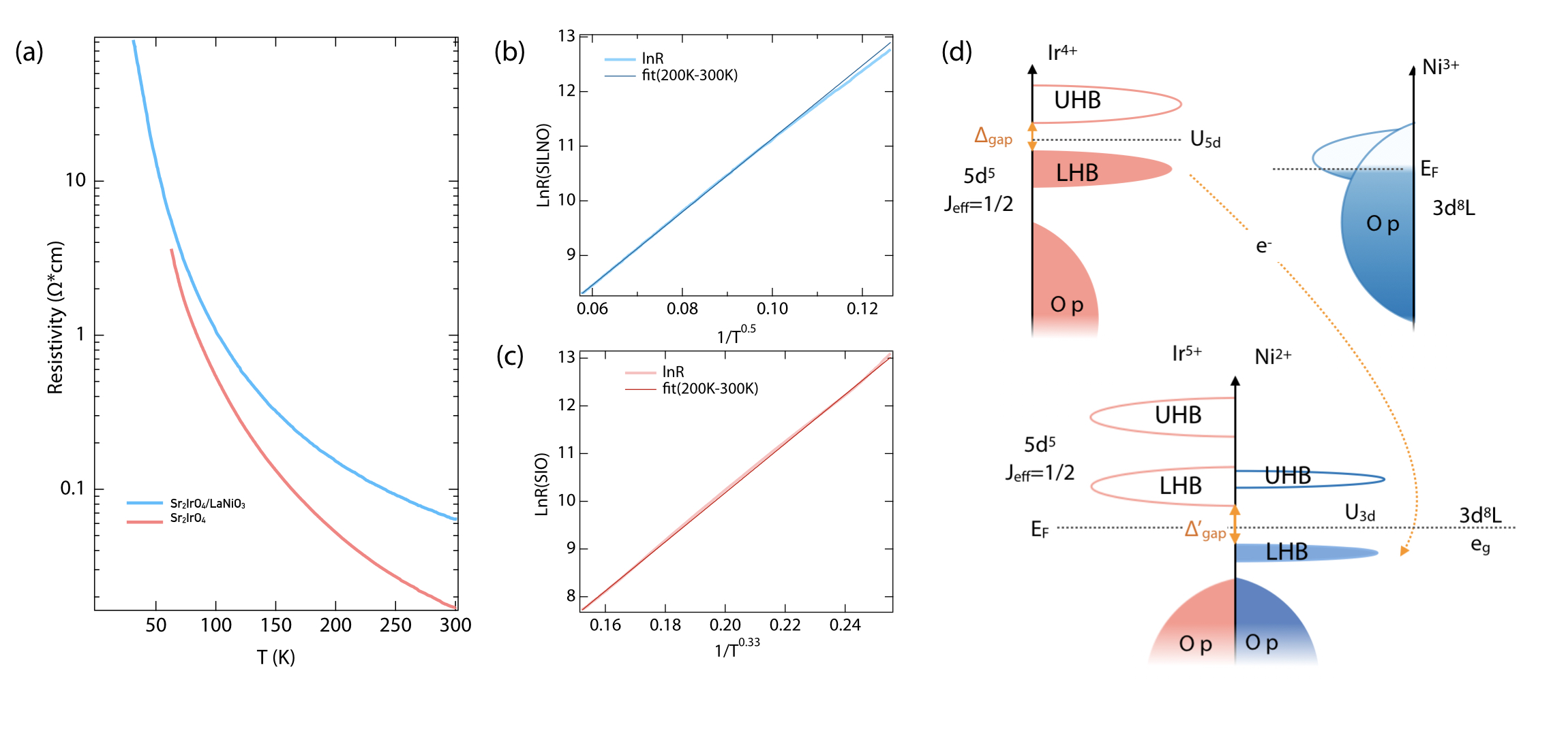
After establishing the orbital reconstructions at the interfaces, a critical question yet remains: Has the hole doping of Sr2IrO4 lead to the formation of a metallic phase? To investigate this issue, the temperature dependence of resistivity on both the superlattice and undoped Sr2IrO4 thin film were carried out from 300 K down to 2 K. As shown in Fig. 3(a), an overall insulating behavior still persists in the superlattice, with the magnitude of resistivity exceeding the measurable limit at 30 K. By fitting the transport result with different variable range hopping (VRH) models: under all different selection () with the same temperature range, we found out that the best fitting model for the doped and undoped system are different. In undoped Sr2IrO4, it fits well with , indicating a conventional 2D Mott variable range hopping(VRH) model (Fig. 3 (c)). This has also been observed in the undoped Sr2IrO4 from other groups, assuming that the band gap in the system is smaller than thermal activation ().[22, 30, 31] On the other hand, for doped Sr2IrO4, the best fitting result comes from the case, which is the Efros-Shklovskii VRH model (Fig. 3 (b)). In this case, a Coulomb gap larger than the thermal activation () is opened, and the electrons becomes more localized after hole doping.[32] In the following, we propose a possible scenario to interpret the electronic reconstruction at Sr2IrO4/LaNiO3 interface.
As seen in Fig. 3 (d), bulk LaNiO3 is a negative charge-transfer metal, whose Fermi surface lies in hybridized O 2 and Ni 3 state[33, 34]. Due to the strong O-Ni hybridization, the electronic structure of bulk LaNiO3 is best represented as a mixture of 3d7 , 3d8L and 3d9 LL (L is a hole on oxygen 2p orbital). [35] For Sr2IrO4, the Fermi surface is between the LHB and UHB of the J=1/2 band. Driven by the chemical potential difference across the Sr2IrO4/LaNiO3 interfaces, electrons are transferred from the Ir to the Ni site. Ir4+ becomes Ir5+ with the fully occupied J = 3/2 band still below the Fermi level.The electron then can fill the hole on oxygens, and reduce the degree of hybridization by lowering the oxygen p orbitals and split the Ni 3d band due to the on-site Coulomb repulsion, U. Since on Ni U is rather large ( 4 eV), splitting of the Ni eg band will likely push the Ni up Hubbard band (UHB) away from the Fermi level and above the Ir J = 1/2 low Hubbard band (LHB) bands. As the result, the band gap at the interface is determined by the energy interval between the top of Ni eg LHB and the bottom of Ir J = 1/2 LHB.
3 CONCLUSION
In conclusion, by growing a Sr2IrO4/LaNiO3 superlattice, we have achieved hole doping of Sr2IrO4 without detrimental effects of chemical disorder. XPS and XAS measurements confirm a charge transfer from Ir4+ to Ni3+, resulting in a markedly fraction of Ir5+ and Ni2+. The latter is accompanied by a lifting of degeneracy in the Ni orbitals, with the d orbital 0.1 eV lower than d, as evidenced by XLD measurements. Hole doping via the interface enhanced the on-site Coulomb interaction and enlarged the magnitude of the band gap in the Sr2IrO4/LaNiO3 heterostructure compared to a Sr2IrO4 single layer. These results explore the phase diagram of Sr2IrO4 on the hole-doping side, and pave an alternative way towards the modification of carrier concentration in the relativistic Mott insulator Sr2IrO4.
4 Acknowledgements
F. W., X. L. and J. C. acknowledged the support by the Gordon and Betty Moore Foundation EPiQS Initiative through Grant No. GBMF4534. M. K. and B. P. were supported by the Department of Energy Grant No. DE-SC0012375. Q. Z. and L. G. were supported by the Strategic Priority Research Program of Chinese Academy of Sciences (Grant No. XDB07030200) and National Natural Science Foundation of China (51522212, 51421002, and 51672307). This research used resources of the Advanced Light Source, which is a DOE Office of Science User Facility under contract no. DE-AC02-05CH11231.
References
- [1] Imada M, Fujimori A, Tokura Y, Rev. Mod. Phys. 70, 1039 (1998).
- [2] Uchida M and Kawasaki M, J. Phys. D: Appl. Phys. 14, 51 (2018).
- [3] Balents L, Nature 464, 199208 (2010).
- [4] Rau J G, Lee E K H, Kee H Y, Annu. Rev. Condens. Matter Phys 7, 195221 (2016).
- [5] Witczak-Krempa W, Chen G, Kim Y B, Balents L, Annu. Rev. Condens. Matter Phys. 5, 5782 (2014).
- [6] Chikara S, Korneta O, Crummett W P, DeLong L E, Schlottmann P, Cao G, Phys. Rev. B 80, 140407 (2009).
- [7] Kim B, Jin H, Moon S, Kim J-Y, Park B-G, Leem C, Yu J, Noh T, Kim C, Oh S-J, Park J-H, Durairaj V, Cao G, Rotenberg E, Phys. rev. lett. 101, 076402 (2008).
- [8] Kim B, Ohsumi H, Komesu T, Sakai S, Morita T, Takagi H, Arima T H, Science 323, 13291332 (2009).
- [9] Cao G, Bolivar J, McCall S, Crow J, Guertin R, Phys. Rev. B 57, R11039 (1998).
- [10] Kim J, Casa D, Upton M, Gog T, Kim Y-J, Mitchell J, Van Veenendaal M, Daghofer M, van Den Brink J, Khaliullin G, Kim B J, Phys. Rev. Lett. 108, 177003 (2012).
- [11] Wang F, Senthil T, Phys. Rev. Lett. 106, 136402 (2011).
- [12] Meng Z Y, Kim Y B, Kee H-Y, Phys. Rev. Lett. 113, 177003 (2014).
- [13] Watanabe H, Shirakawa T, Yunoki S, Phys. Rev. Lett. 110, 027002 (2013).
- [14] Yan Y, Ren M, Xu H, Xie B, Tao R, Choi H, Lee N, Choi Y, Zhang T, Feng D, Phys. Rev. X 5, 041018 (2015).
- [15] Cao Y, Wang Q, Waugh J A, Reber T J, Li H, Zhou X, Parham S, Park S R, Plumb N C, Rotenberg E, Bostwick A, Nat. Commun. 7, 11367 (2016).
- [16] Zhao L, Torchinsky D H, Chu H, Ivanov V, Lifshitz R, Flint R, Qi T, Cao G and Hsieh D, Nat. Phys. 12, 32-36 (2016).
- [17] de la Torre A, McKeown Walker S, Bruno F Y, Riccó S, Wang Z, Gutierrez Lezama I, Scheerer G, Giriat G, Jaccard D, Berthod C, Kim T K, Hoesch M, Hunter E C, Perry R S, Tamai A, Baumberger F, Phys. Rev. Lett. 115, 176402 (2015).
- [18] Kim Y K, Sung N H, Denlinger J D and Kim B J, Nat. Phys. 12, 37 (2016).
- [19] Chen X, Schmehr J L, Islam Z, Porter Z, Zoghlin E, Finkelstein K, Ruff J P, Wilson S D, Nat. Commun. 9, 103 (2018).
- [20] Korneta O, Qi T, Chikara S, Parkin S, De Long L, Schlottmann P, Cao G, Phys. Rev. B 82, 115117 (2010).
- [21] Ravichandran J, Serrao C R, Efetov D K, Yi D, Oh Y S, Cheong S-W, Ramesh R, Kim P, J. Phys.: Condens. Matter 28 505304 (2016).
- [22] Li M, Liu Z, Yang H, Zhao J, Yao Q, Fan C, Liu J, Gao B, Shen D, Xie X, Chin. Phys. Lett 32, 5 057402 (2015).
- [23] Banerjee A, Sannigrahi J, Giri S, Majumdar S, Phys. Rev. B 96, 224426 (2017).
- [24] Kumar H, Dhaka R, Pramanik A, Phys. Rev. B 95, 054415 (2017).
- [25] Zhu W K, Wang M, Seradjeh B, Yang F, Zhang S, Phys. Rev. B 90, 054419 (2014).
- [26] Liu X, Cao Y, Pal B, Middey S, Kareev M, Choi Y, Shafer P, Haskel D, Arenholz E, and Chakhalian J, Phys. Rev. M 1, 075004 (2017).
- [27] Cui B, Song C, Li F, Wang G, Mao H, Peng J, Zeng F, Pan F, Sci. Rep. 4, 4206 (2014).
- [28] Pesquera D, Herranz G, Barla A, Pellegrin E, Bondino F, Magnano E, Sánchez F, Fontcuberta J, Nat. Commun. 3, 1189 (2012).
- [29] Chakhalian J, Rondinelli J M, Liu J, Gray B A, Kareev M, Moon E J, Prasai N, Cohn J L, Varela M, Tung I C, Bedzyk M J, Phys. Rev. Lett 107, 116805 (2011).
- [30] Lu C, Quindeau A, Deniz H, Preziosi D, Hesse D, and Alexe M, Appl. Phys. Lett. 105, 082407 (2014).
- [31] Mott N F, Philos. Mag. 19 160: 835-852 (1969).
- [32] Efros A L and Shklovskii B I, J. Phys. C: Solid State Physics 8 4 (1975).
- [33] Dobin A Y, Nikolaev K, Krivorotov I, Wentzcovitch R, Dahlberg E D, Goldman A, Phys. Rev. B 68, 113408 (2003).
- [34] Guo H, Li Z, Zhao L, Hu Z, Chang C, Kuo C-Y, Schmidt W, Piovano A, Pi T, Sobolev O, Khomskii D I, Tjeng L H, Komarek A C, Nat. Commun. 9, 2206 (2018).
- [35] Golalikhani M, Lei Q, Chandrasena R U, Kasaei L, Park H, Bai J, Orgiani P, Ciston J, Sterbinsky G E, Arena D A, Shafer P, Nat. Commun. 9, 2206 (2018).