LTE Standard-Compliant D2D Communication: Software-defined Radio Implementation and Evaluation
Abstract
In this paper, we describe the design and implementation of Device-to-Device (D2D) communication functionality for Long Term Evolution (LTE). To our knowledge, this is the first such implementation that is compliant with the LTE Release 12 standard. We implement our system on a software-defined radio Software-Defined Radio (SDR) testbed, augmenting the open-source LTE eNodeB and User Equipment (UE) implementation provided by the srsLTE software suite. Our measurements demonstrate the cell extension capabilities of D2D and quantify the Signal-to-Noise Ratio (SNR) and throughput obtained by a subscriber when directly served by the eNodeB and when provided connectivity through the relay UE. Our implementation of sidelink, relaying, and mode selection functionality enables experimentation and prototyping of D2D communication that can assist in standardization, research, and development.
Index Terms:
LTE, standard, D2D, SDR, sidelink.I Introduction
4G mobile network standards are being extended to support D2D communications, functionality that is also expected to be present in 5G [1]. Standardization efforts from the Third Generation Partnership Project (3GPP) are ongoing to provide LTE with D2D and relaying capabilities, aiming to achieve coverage extension and improved transmission reliability [2]. D2D communication can also support proximity services and public safety use of LTE networks.
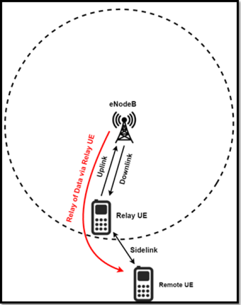
The Physical (PHY) communication link between two UEs is referred to as a sidelink, standardized in LTE Release 12 [2], involving user discovery, synchronization, and data transmission. In some locations (e.g. in the edge of cells) where coverage from the LTE base station cannot be guaranteed because of low SNR, it is possible to use a UE as a relay from the eNodeB to a more remote UE, as illustrated in Fig. 1. As the user may exhibit mobility and channel conditions change from time to time, dynamic mode selection functionality between infrastructure mode (eNodeB-to-UE) and D2D mode (UE-to-UE) is needed.
In this paper we develop the first SDR PHY layer sidelink implementation compliant with the 3GPP LTE standard (Release 12). We also implement functionality to relay data received from an eNodeB (in the downlink) to the remote UE (through the sidelink), as well as mode selection functionality to allow the remote UE to switch between sidelink mode and downlink mode according to network conditions. We extend an open source SDR platform, srsLTE [3], with our implementation of the sidelink. This allows us to dynamically control the radio parameters, e.g. frequency, gain, and Modulation and Coding Scheme (MCS) index. We also develop controllers with Graphical User Interfaces (GUIs) that allow experimenters to change radio parameter settings on the fly. Our testbed employs the Universal Software Radio Peripheral (USRP) platform [4]. We report measurement results of SNR, throughput and Block Error Rate (BLER) and discuss how these can be used as the criteria for mode selection between direct downlink and relaying through the sidelink. Our implementation of the sidelink, relaying, and mode selection in open source LTE software enables experimentation and prototyping that can assist in standardization, research and development.
D2D communication has been a topic of much recent research, as discussed in the survey [5]. However, only a few research works have developed testbed implementations for testing the performance of systems that rely on D2D communications. For instance, the authors of [6] present the measurement results of power consumption and received signal strength indicator (RSSI) for their D2D communication in a testbed of sensor nodes following the IEEE 802.15.4 standard. The authors of [7] integrate D2D communication and Software Defined Networks (SDN) by adding Medium Access Control (MAC) layer functionality (TDMA, SCMA, etc.) to the basic Orthogonal Frequency Division Multiplexing (OFDM)-based PHY layer transmission; the SDN controller is then implemented on top of the MAC layer protocol. The authors of [8] investigate cross-link interference management in a proposed multi-user D2D network scenario. The experiment in the paper was carried out by using basic OFDM physical transmission. However, none of the works mentioned above has produced sidelink implementations that conform to the current 3GPP LTE standardization of D2D communication. To the best of our knowledge, ours is the first PHY layer implementation of D2D communication that is compliant with LTE Release 12 specifications.
For implementing the sidelink communication and relay functionality, and to make it compliant with the LTE standard, we have used the srsLTE library [3], an open source PHY layer platform for software-defined radio implementation of the Frequency Division Duplex (FDD) mode of LTE [9]. The library follows a modular approach, which helps in combining different PHY layer Digital Signal Processing (DSP) components together without the need to change every element. We have extended the code, implementing the sidelink and relay functionalities while also making use of existing components in srsLTE, namely the uplink and downlink modules, which are compliant to 3GPP LTE Release 8.
This work is conducted in the context of the Horizon 2020 (H2020) Elastic Wireless Network Experimentation (eWINE) project, which focuses on experimental research towards flexible, on-demand end-to-end wireless connectivity. This elastic network connectivity requires the dynamic reallocation of network resources. Our work in this paper implements D2D capabilities in the LTE network which can then be used to dynamically establish a sidelink or a link directly with the eNodeB, depending on current network conditions.
II Design and Implementation
As described in the previous section, our design and implementation focuses on the LTE sidelink and relay functionality. In this section, we outline the major technical challenges in implementing this functionality. The first challenge is to develop the sidelink PHY layer data transmission channels, which adopt a Single Carrier Frequency Division Multiple Access (SC-FDMA) waveform, according to the LTE standard. The second challenge is to build the relay functionality for the UE. The third challenge is to design the mode selection functionality in the remote UE to establish either a sidelink (with the relay UE) or a downlink connection (with the eNodeB).
II-A Implementation of Physical Sidelink Shared Channel (PSSCH) with SC-FDMA
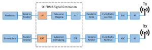
The PSSCH is the PHY channel for data transmission on the sidelink. According to the 3GPP LTE standard Release 12, the PSSCH must use SC-FDMA for data transmission. The main difference in implementation between SC-FDMA and OFDM (which is used in the downlink) is that an additional Discrete Fourier Transform (DFT) is needed in the transmitter and an additional Inverse Discrete Fourier Transform (IDFT) is needed in the receiver, as shown in Fig. 2. We implement the PSSCH by inserting the DFT and IDFT modules, available at the FFTW3 and srsLTE software library, into the OFDM radio DSP chain for the PSSCH.
A Physical Sidelink Control Channel (PSCCH) is also needed for accomplishing the functionality of PSSCH. In our sidelink implementation, three symbols per subframe are allocated for the PSCCH, and Sidelink Control Information (SCI) is included in these symbols. The SCI may include information on the MCS, a group destination identifier, the resource block assignment and hopping resource allocation, a frequency hopping flag, etc. In our implementation we include minimum functionality for the PSCCH, supporting flexible MCS selection by the sidelink controller (to be described in the following sections). For the moment, we assign the entire set of resource blocks in the frequency channel of the sidelink to a single pair of UEs.
II-B Implementation of relay functionality in the UE
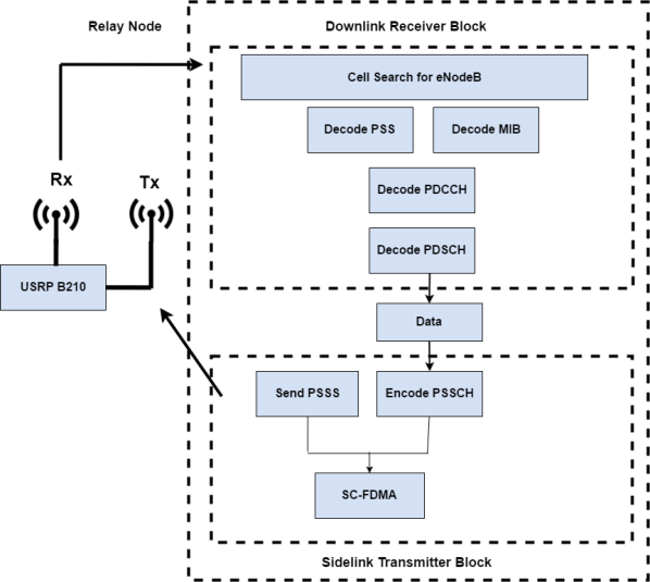
The relay UE is called upon to relay the data received in the downlink to the remote UE, communicating over the sidelink. In order to run the downlink and sidelink in parallel, we create two different threads, which individually perform the two sets of operations without interrupting each other. The internal functionality of the relay UE is shown in Fig. 3. A UE must establish the link with the eNodeB, first searching for beaconing signals periodically transmitted by the base station (in the figure, this process is referred to as a cell search). After the downlink is established, the UE must decode the Primary Synchronization Signal (PSS) and Master Information Block (MIB) signals to synchronize with the eNodeB. Then, it decodes the Physical Downlink Control Channel (PDCCH) and the Physical Downlink Shared Channel (PDSCH) signals to receive data, which subsequently needs to be forwarded to the remote UE over the sidelink. This data is then transmitted over the PSSCH using SC-FDMA. The Primary Sidelink Synchronization Signal (PSSS) signal is also generated simultaneously, for synchronization between two UEs that have established a sidelink.
II-C Implementation of mode switching
We implement functionality for the remote UE that enables it to switch between sidelink and downlink modes of operation in real time. A controller is needed to perform this mode switching with minimum latency. We implement our controller with two separate threads: one calls up the OFDM receiver for the downlink and the other one calls up the receiver for the sidelink. The threads run the individual Linux bash commands which can boot either the downlink or sidelink program automatically. For experimental purposes, we build a Graphical User Interface (GUI) on top of this controller that can be used by an experimenter to manually switch between operation modes, as further described in section IV.
III Experimental Results
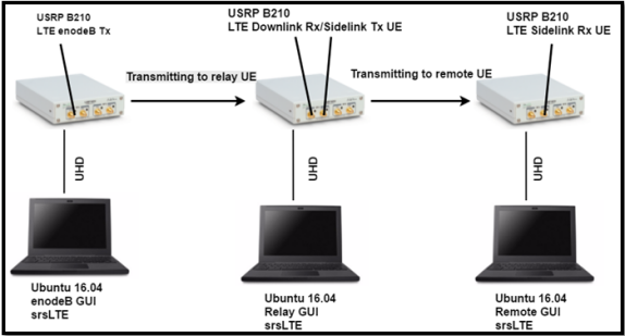
To verify the correct operation of the solutions described above, and to collect performance measurement results, we have set up an experiment as shown in Fig. 4. The figure shows the eNodeB on the left hand side, a UE that serves as a relay in the middle, and the remote UE on the right hand side. For the experiments reported here, we adopted the USRP reconfigurable radio model B210 and the USRP Hardware Driver (UHD) interface. The USRP B210 hardware supports a 30.72 MHz clock, matching LTE sampling frequencies and enabling the decoding of signals from live LTE base stations. Our experiment consists of three USRP B210 and three laptops running srsLTE software, extended with our sidelink and relay implementation. Each USRP connects to a different laptop through a UHD driver and USB 3.0.
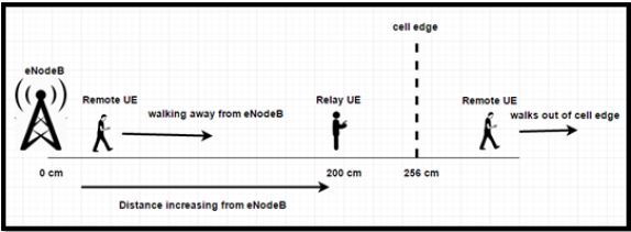
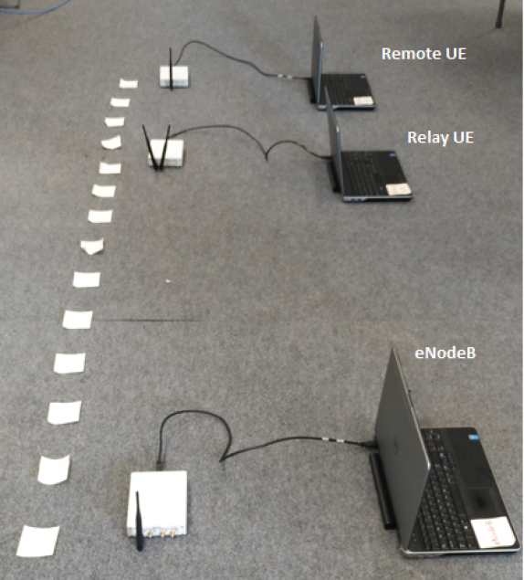
In our measurements we maintain the locations of eNodeB and relay UE fixed and move the remote UE, starting from the position of the eNodeB, towards the edge of the cell as depicted in Fig. 5. A photograph of the measurement set-up is shown in Fig. 6. The measurements focus on how the SNR and throughput vary with the position of the remote UE. In the tests, a downlink signal is transmitted from the eNodeB to the remote UE and sidelink signal is transmitted from the relay UE to the remote UE. To accommodate the range restrictions of the RF hardware and the space available in the laboratory where the experiments took place, we fixed the transmitter gain for the eNodeB at 55 dB, yielding a cell boundary at approximately 256 cm.
The following subsections describe the measurement results.
III-A SNR measurements and mode selection
Fig. 7 shows the average SNR as a function of distance, measured from the location of the eNodeB to the remote UE, for both the sidelink (orange curve) and downlink (blue curve), when the transmitter gain of the sidelink is fixed at 40 dB. (This is lower than the transmitter gain for the downlink because the relay UE is supposed to have lower power consumption for transmission and lower coverage than an eNodeB.) It is clear that, up to around 160 cm from the eNodeB, the downlink offers superior SNR to the sidelink; past that point, establishing a sidelink to a relay UE provides an SNR advantage. Beyond a distance of around 240 cm from the eNodeB, the only option available to the remote UE is to set up a sidelink: this illustrates the range extension capabilities of D2D.
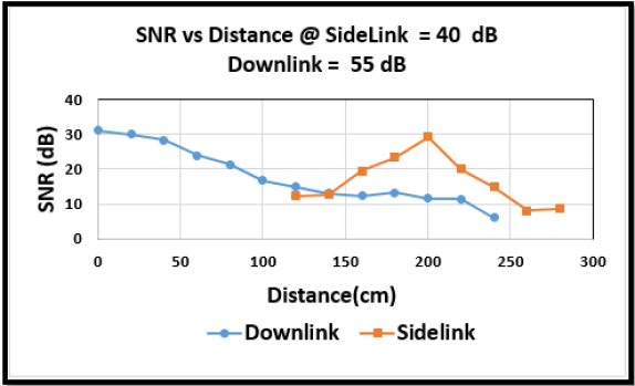
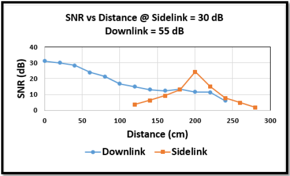
Fig. 8 shows similar results of average SNR versus distance, but in this case the sidelink transmitter gain has been set to 30 dB. We can see that around 180 cm is the switching point from downlink to sidelink, if the objective is to maximize SNR. We can also see that the SNR for the sidelink is lower than that reported in Fig. 7, and the effective range extension is also reduced, reflecting the lower setting for the sidelink gain.
Each point in Fig. 7 and Fig. 8 is the average of 1000 collected measurements. We also report the standard deviation, the width of the 95% confidence internal, minimum, and maximum SNR in the Tables I, II, and III. Statistical analysis reveals that, for each value of distance, the SNR varies very little and hence we have very tight confidence intervals.
| Distance | Average | Standard | Confidence | Max | Min |
|---|---|---|---|---|---|
| (cm) | (dB) | Deviation (dB) | Interval (dB) | (dB) | (dB) |
| 120 | 3.6403 | 0.0812 | 0.0050 | 3.9 | 3.4 |
| 140 | 6.2020 | 0.1803 | 0.0112 | 6.7 | 5.1 |
| 160 | 9.1434 | 0.2460 | 0.0152 | 9.7 | 8.4 |
| 180 | 12.9839 | 0.1278 | 0.0079 | 13.3 | 12.1 |
| 200 | 24.2176 | 0.3149 | 0.0195 | 24.9 | 23.2 |
| 220 | 15.087 | 0.2635 | 0.0163 | 15.9 | 14.1 |
| 240 | 7.6485 | 0.2282 | 0.0141 | 8.2 | 6.8 |
| 260 | 4.7130 | 0.2316 | 0.0144 | 5.1 | 2.7 |
| 280 | 1.9099 | 0.5534 | 0.0343 | 2.2 | 1.5 |
| Distance | Average | Standard | Confidence | Max | Min |
|---|---|---|---|---|---|
| (cm) | (dB) | Deviation (dB) | Interval (dB) | (dB) | (dB) |
| 120 | 12.3448 | 0.3534 | 0.0219 | 13.5 | 11.5 |
| 140 | 12.6533 | 0.1633 | 0.0101 | 13.2 | 12.0 |
| 160 | 19.5281 | 0.2237 | 0.0139 | 20.1 | 18.8 |
| 180 | 23.6827 | 0.4287 | 0.0266 | 24.6 | 22.6 |
| 200 | 29.2872 | 0.8827 | 0.0547 | 30.7 | 26.8 |
| 220 | 19.9731 | 0.2355 | 0.0146 | 20.7 | 19.2 |
| 240 | 14.9266 | 0.1093 | 0.0068 | 15.2 | 14.6 |
| 260 | 8.1482 | 0.1636 | 0.0101 | 8.5 | 7.3 |
| 280 | 8.5819 | 0.2286 | 0.0142 | 9.1 | 7.3 |
| Distance | Average | Standard | Confidence | Max | Min |
|---|---|---|---|---|---|
| (cm) | (dB) | Deviation (dB) | Interval (dB) | (dB) | (dB) |
| 0 | 31.1044 | 1.5805 | 0.0980 | 34.0 | 27.9 |
| 20 | 29.8855 | 1.1352 | 0.0704 | 32.2 | 27.2 |
| 40 | 28.3759 | 0.7280 | 0.0451 | 29.9 | 26.8 |
| 60 | 23.8751 | 1.0637 | 0.0659 | 25.3 | 14.7 |
| 80 | 21.3312 | 1.0483 | 0.0650 | 23.1 | 16.4 |
| 100 | 16.6697 | 1.5552 | 0.0964 | 18.3 | 12.4 |
| 120 | 14.8763 | 0.7983 | 0.0495 | 17.3 | 12.6 |
| 140 | 13.1189 s | 0.9459 | 0.0586 | 15.5 | 9.0 |
| 160 | 12.2334 | 0.8596 | 0.0533 | 15.1 | 9.2 |
| 180 | 13.2411 | 0.7260 | 0.0450 | 15.2 | 11.0 |
| 200 | 11.6577 | 0.8913 | 0.0552 | 13.5 | 9.1 |
| 220 | 11.3320 | 0.3551 | 0.0220 | 12.3 | 10.2 |
| 240 | 6.0951 | 0.3073 | 0.0190 | 6.9 | 3.2 |
III-B Throughput measurements and mode selection
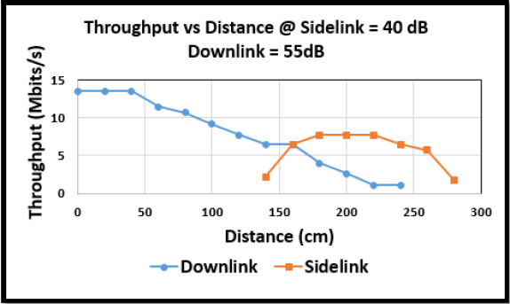
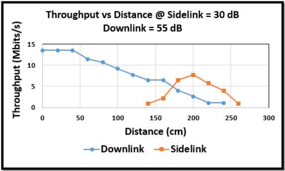
We also measure the maximum throughout using the same experimental setup shown in Fig. 5 and Fig. 6. In the 3GPP LTE standard, the throughput is determined by the MCS index and number of Physical Resource Blocks (PRBs) utilized for transmission. We allocate 25 PRBs for both downlink and sidelink in our experiment. Therefore, at each measurement location we seek to reach the maximum throughput by increasing the MCS index of the transmitters, for the downlink and sidelink, and record the maximum throughput while the observed Block Error Rate (BLER) remains at zero. The highest modulation for the downlink is 64 Quadrature Amplitude Modulation (QAM) and the highest modulation for the sidelink is 16 QAM according to the LTE standard. Figs. 9 and 10 show how the throughput varies according to the position of the remote UE; the trends follow closely those reported for the SNR.
IV Controller GUI for dynamic parameter settings
We also built a user interface that allows experimenters to change the radio parameters, such as frequency, gain, and MCS, on the fly for the eNodeB, relay UE and remote UE. We used the pThread library in C to create threads that receive external commands from users and translate them into parameters settings in the srsLTE implementation. We used the GTK+ 3.0 library in C to implement the GUIs, and we implemented the communication between the GUI and our LTE software (based on a client-server scheme) using Linux socket interprocess communication libraries. The elements of our implementation include:
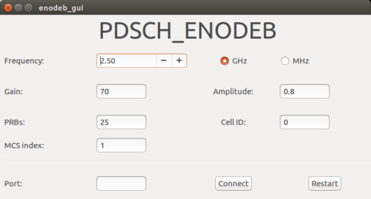
IV-1 Controller GUI for eNodeB
This eNodeB controller GUI (shown in Fig. 11) has the functionality to change frequency, gain, PRBs, amplitude, MCS index and cell ID.
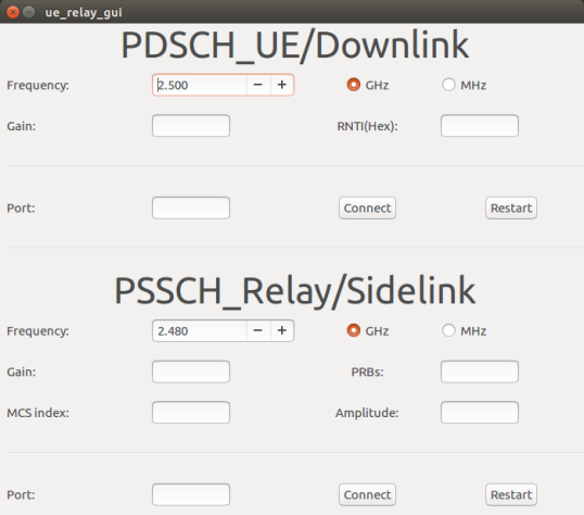
IV-2 Controller GUI for relay UE
The controller GUI for the relay UE, shown in Fig. 12, provides an interface for the downlink receiver and the sidelink transmitter, as the relay UE performs both functions at the same time. For the downlink receiver, the experimenter can change frequency, gain, and Radio Network Temporary Identifier (RNTI). For the sidelink transmitter, the experimenter can change frequency, gain, amplitude, PRBs and MCS Index. This GUI has two different socket port options to connect to the LTE software, so that the downlink and sidelink parameters are controlled separately via different Linux socket ports, providing additional flexibility to the experimenter.
IV-3 Controller GUI for remote UE
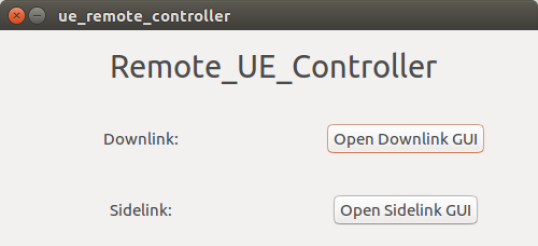
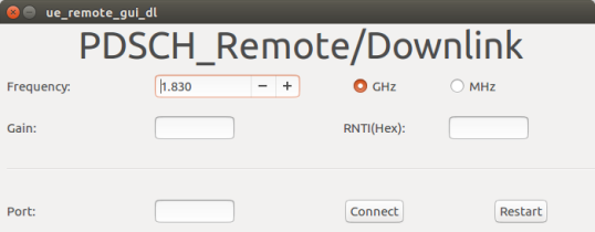
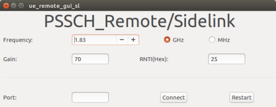
The controller GUI for the remote UE comprises three GUI windows. The first GUI acts as the controller through which the mode selection between downlink and sidelink can be performed (shown in Fig. 13). If the experimenter selects the downlink mode, the LTE radio software for the downlink automatically boots up and the GUI for the downlink opens up (as shown in Fig. 14), and similarly for the sidelink mode (as shown in Fig. 15. The parameters which the experimenter can control through downlink or sidelink GUI are similar to those of the downlink GUI for the relay UE.
V Conclusion
In this paper, we have implemented the first LTE standard-compliant SDR sidelink PHY layer data transmission. We have built a relay UE to relay the data received from an eNodeB (through the downlink) to a remote UE (through the sidelink). We have also developed functionality for mode selection between infrastructure mode and D2D mode on the remote UE, providing experimenters with a GUI that allows them to perform mode selection and change the radio parameters on the fly. Our measurement results show that the sidelink relay can provide range extension for the cell.
Our ongoing work includes the development of intelligent mode selection (UE-to-UE versus UE-to-eNodeB) according to network conditions, as well as enhanced PSCCH functionality, including user discovery and resource management.
- 3GPP
- Third Generation Partnership Project
- BLER
- Block Error Rate
- D2D
- Device-to-Device
- DFT
- Discrete Fourier Transform
- DSP
- Digital Signal Processing
- eWINE
- Elastic Wireless Network Experimentation
- FDD
- Frequency Division Duplex
- GUI
- Graphical User Interface
- IDFT
- Inverse Discrete Fourier Transform
- LTE
- Long Term Evolution
- MAC
- Medium Access Control
- MCS
- Modulation and Coding Scheme
- MIB
- Master Information Block
- OFDM
- Orthogonal Frequency Division Multiplexing
- PDCCH
- Physical Downlink Control Channel
- PDSCH
- Physical Downlink Shared Channel
- PHY
- Physical
- PRBs
- Physical Resource Blocks
- PSBCH
- Physical Sidelink Broadcast Channel
- PSCCH
- Physical Sidelink Control Channel
- PSDCH
- Physical Sidelink Discovery Channel
- PSS
- Primary Synchronization Signal
- PSSCH
- Physical Sidelink Shared Channel
- PSSS
- Primary Sidelink Synchronization Signal
- QAM
- Quadrature Amplitude Modulation
- QoS
- quality of service
- RNTI
- Radio Network Temporary Identifier
- RSSI
- received signal strength indicator
- SC-FDMA
- Single Carrier Frequency Division Multiple Access
- SCI
- Sidelink Control Information
- SDMA
- Space Division Multiple Access
- SDN
- Software Defined Networks
- SDR
- Software-Defined Radio
- SNR
- Signal-to-Noise Ratio
- TDMA
- Time Division Multiple Access
- UE
- User Equipment
- UHD
- USRP Hardware Driver
- USRP
- Universal Software Radio Peripheral
Acknowledgment
This publication has emanated from research supported by the European Commission Horizon 2020 Programme under grant agreement no. 688116 (eWINE). We also thank Mr. Robson Couto for his effort on developing the first version of Graphical User Interface, and Software Radio System (SRS) for technical support on srsLTE software.
References
- [1] Rohde & Schwarz. (2013, Sep.) Device to Device Communication in LTE Whitepaper. Accessed: Mar. 2017. [Online]. Available: https://cdn.rohde-schwarz.com/pws/dl_downloads/dl_application/application_notes/1ma264 /1MA264_0e_D2DComm.pdf
- [2] 3GPP, “LTE Release 12,” Accessed: Oct. 2016. [Online]. Available: http://www.3gpp.org/specifications/releases/68-release-12
- [3] srsLTE, “Open source 3GPP LTE library,” Accessed: Oct. 2016. [Online]. Available: https://github.com/srsLTE/srsLTE
- [4] Ettus Research. USRP B210 USB Software Defined Radio (SDR). Accessed: Mar. 2017. [Online]. Available: https://www.ettus.com/product/details/UB210-KIT
- [5] A. Asadi, Q. Wang, and V. Mancuso, “A Survey on Device-to-Device Communication in Cellular Networks,” IEEE Communications Surveys Tutorials, vol. 16, no. 4, pp. 1801–1819, Fourth quarter 2014.
- [6] V. K. Singh, H. Chawla, and V. A. Bohara, “Measurement Results for Direct and Single Hop Device-to-device Communication Protocol,” in International Conference on Advances in Computing, Communications and Informatics (ICACCI), Sep. 2016, pp. 2515–2520.
- [7] M. Zhou, H. Zhang, S. Zhang, L. Song, Y. Li, and Z. Han, “Design and Implementation of Device-to-device Software-defined Networks,” in IEEE International Conference on Communications (ICC), May 2016, pp. 1–6.
- [8] S. L. Chiu, K. C. J. Lin, G. X. Lin, and H. Y. Wei, “Empowering Device-to-Device Networks with Cross-Link Interference Management,” IEEE Transactions on Mobile Computing, vol. PP, no. 99, pp. 1–1, Jun. 2016.
- [9] I. Gomez-Miguelez, A. Garcia-Saavedra, P. D. Sutton, P. Serrano, C. Cano, and D. J. Leith, “srsLTE: An Open-source Platform for LTE Evolution and Experimentation,” in Proceedings of the Tenth ACM International Workshop on Wireless Network Testbeds, Experimental Evaluation, and Characterization (WiNTECH). ACM, 2016, pp. 25–32. [Online]. Available: http://doi.acm.org/10.1145/2980159.2980163