Spin injection and pumping generated by a direct current
flowing through a magnetic tunnel junction
Abstract
A charge flow through a magnetic tunnel junction (MTJ) leads to the generation of a spin-polarized current which exerts a spin-transfer torque (STT) on the magnetization. When the density of applied direct current exceeds some critical value, the STT excites high-frequency magnetization precession in the ”free” electrode of MTJ. Such precession gives rise to microwave output voltage and, furthermore, can be employed for spin pumping into adjacent normal metal or semiconductor. Here we describe theoretically the spin dynamics and charge transport in the CoFeB/MgO/CoFeB/Au tunneling heterostructure connected to a constant-current source. The magnetization dynamics in the free CoFeB layer with weak perpendicular anisotropy is calculated by numerical integration of the Landau-Lifshitz-Gilbert-Slonczewski equation accounting for both STT and voltage controlled magnetic anisotropy associated with the CoFeBMgO interface. It is shown that a large-angle magnetization precession, resulting from electrically induced dynamic spin reorientation transition, can be generated in a certain range of relatively low current densities. An oscillating spin current, which is pumped into the Au overlayer owing to such precession, is then evaluated together with the injected spin current. Considering both the driving spin-polarized charge current and the pumped spin current, we also describe the charge transport in the CoFeB/Au bilayer with the account of anomalous and inverse spin Hall effects. An electric potential difference between the lateral sides of the CoFeB/Au bilayer is calculated as a function of distance from the CoFeBMgO interface. It is found that this transverse voltage signal in Au is large enough for experimental detection, which indicates significant efficiency of the proposed current-driven spin injector.
I Introduction
In conductive ferromagnetic nanolayers, magnetic dynamics can be induced by a spin-polarized charge current exerting a spin-transfer torque (STT) on the magnetization Slonczewski1989_6995 ; Slonczewski2007_169 . The STT results from the transfer of angular momentum and provides the opportunity to excite high-frequency magnetization oscillations in nanomagnets by applied direct or alternating (microwave) current Kiselev2003_380 -Fang2016_11259 . Furthermore, spin-polarized charge currents with sufficiently high densities lead to magnetization switching in metallic pillars Myers1999_867 ; Katine2000_3149 and magnetic tunnel junctions (MTJs) Huai2004_3118 -Sato2011_042501 . Such current-induced switching serves as a mechanism for data writing in magnetic random access memories utilizing the STT effect (STT-MRAMs) Ikeda2007_991 -Ando2014_172607 , while the magnetization precession driven by direct currents in spin-torque nanoscale oscillators (STNOs) creates microwave voltages, which makes STNOs potentially useful as frequency-tunable microwave sources and detectors Bonetti2009_102507 -Fang2016_11259 .
In ferromagnetic nanostructures comprising insulating interlayers, the electric field created in the insulator adjacent to the metallic ferromagnet may significantly affect the magnetic anisotropy of the latter. Such voltage-controlled magnetic anisotropy (VCMA) results from the penetration of electric field into an atomically thin surface layer of the ferromagnetic metal, which modifies the interfacial magnetic anisotropy Weisheit2007_349 -Alzate2014_112410 . The presence of VCMA renders possible to induce the magnetization precession in ferromagnetic nanostructures by microwave voltages Nozaki2012_491 -Miura2017_42511 . It is also shown that the application of dc voltage to the ferromagnetic nanolayer possessing VCMA can lead to a spin reorientation transition (SRT) Duan2008_122905 -Pertsev2014_024426 . Moreover, precessional 180∘ magnetization switching using electric field pulses has been demonstrated experimentally Shiota2012_39 ; Grezes2016_012403 . In addition, the voltage dependence of the interfacial magnetic anisotropy in CoFeB/MgO/CoFeB tunnel junctions may greatly reduce the critical current density required for the STT-driven magnetization reversal Wang2011_64 ; Pertsev2013_02757 .
Importantly, magnetization precession in a ferromagnetic layer gives rise to spin pumping into adjoining normal metal or semiconductor Tserkovnyak2002_117601 -Ando2011_655 . In this paper, we theoretically study the magnetization dynamics driven by a direct current applied to the Co20Fe60B20/MgO/Co20Fe60B20 tunnel junction and calculate the time-dependent spin current generated in the Au overlayer. The magnetization evolution in the free Co20Fe60B20 layer is determined by solving numerically the Landau-Lifshitz-Gilbert-Slonczewski (LLGS) equation, which accounts for the STT created by a spin-polarized tunnel current and for the VCMA associated with the Co20Fe60BMgO interface. A range of current densities is revealed, within which a steady-state magnetization precession is generated in the free Co20Fe60B20 layer. For this ”precession window”, frequencies and trajectories of magnetization oscillations are determined and used to calculate the time-dependent spin current created in the Au overlayer. Our calculations are distinguished by the account of both the spin polarization of the charge current and the precession-driven spin pumping as well as the contribution of the latter to the damping of magnetization dynamics. Finally, we solve coupled drift-diffusion equations for charge and spin currents to determine the spatial distribution of the electric potential in the Co20Fe60B20/Au bilayer.
II CURRENT-DRIVEN MAGNETIZATION DYNAMICS
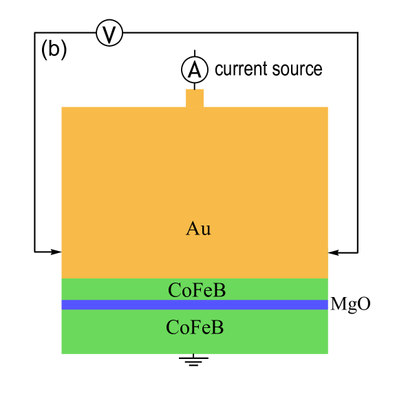
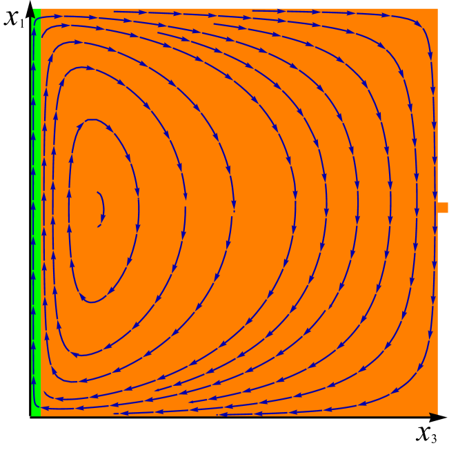
We consider an MTJ comprising an ultrathin free layer with the thickness smaller than the critical thickness , below which it acquires a perpendicular magnetic anisotropy Kanai2012_122403 ; Ikeda2010_721 . The thickness of the pinned layer is taken to be larger than so that the pinned magnetization Mp has an in-plane orientation (Fig. 1). Both layers are assumed to be homogeneously magnetized, and the current flowing through the tunnel barrier is regarded uniform.
![[Uncaptioned image]](/html/1904.10361/assets/x1.png)
To describe the dynamics of the free-layer magnetization M, we employ the macrospin approximation, which is well-suited for magnetic layers with nanoscale in-plane dimensions. Since the magnetization magnitude = at a fixed temperature much lower than the Curie temperature can be considered a constant quantity, the LLGS equation may be reformulated for the unit vector Brataas2012_372 and written as
| (1) |
where is the electron’s gyromagnetic ratio, is the permeability of vacuum, is the Gilbert damping parameter, and is the effective field acting on the magnetization. In Eq. (1), the last term takes into account the STT proportional to the current density in the free layer, whereas the field-like torque is disregarded because it does not affect the magnetic dynamics qualitatively Fang2016_11259 ; Zhu2012_197203 . For symmetric MTJs, the theory gives , where is the elementary (positive) charge, is the reduced Planck constant, and and are the MTJ conductances per unit area in the states with parallel and antiparallel electrode magnetizations, respectively Slonczewski2007_169 . Since we consider the MTJ connected to a constant-current source, the voltage drop across the tunnel barrier depends on the junction’s conductance , which leads to a non-sinusoidal dependence of the STT on the angle between m and . The effective field involved in Eq. (1) is defined by the relation , where is the Helmholtz free energy density of ferromagnetic layer. For a homogeneously magnetized unstrained free layer made of cubic ferromagnet, the magnetization-dependent part of the effective volumetric energy density may be approximated by the polynomial
| (2) |
where ( = 1, 2, 3) are the direction cosines of M in the crystallographic reference frame with the axis orthogonal to the layer surfaces, and are the coefficients of the fourth- and sixth-order terms defining the cubic magnetocrystalline anisotropy, is the parameter characterizing the total specific energy of two interfaces (Co20Fe60BMgO and Co20Fe60BAu in our case), is the energy of interlayer exchange coupling (IEC) with the pinned layer (per unit area), are the demagnetizing factors ( and are negligible at in-plane dimensions , ), and H is the average magnetic field acting on the free layer. Since the magnetic anisotropy associated with the Co20Fe60BMgO interface depends on the electric field in MgO Kanai2012_122403 ; Alzate2014_112410 , the coefficient is a function of the current density . Using a linear approximation for the dependence supported by first-principles calculations Niranjan2010_222504 and experimental data Alzate2014_112410 , we arrive at the relation , where , is the electric-field sensitivity of , and is the voltage drop across the MgO layer of thickness , which is caused by the tunnel current flowing through the junction with the conductance per unit area.
The numerical integration of Eq. (1) was realized with the aid of the projective Euler scheme, where the condition is satisfied automatically. A fixed integration step fs was used in our computations. The effective field was determined from Eq. (2) under the assumption of negligible total magnetic field H acting on the free layer, which is justified by the absence of external magnetic sources and zero mean value of the current-induced Oersted field. Since in the considered heterostructure the magnetization dynamics in the free layer leads to the spin pumping into adjacent nonmagnetic layer, the parameters and involved in Eq. (1) were renormalized as Tserkovnyak2002_117601
| (3) |
where and denote the bulk values of and , is the Landé factor, is the Bohr magneton, and is the complex reflection spin-mixing conductance per unit area of the ferromagnet/normal metal contact Zwierzycki2005_064420 . The Gilbert parameter was regarded as a constant quantity, because numerical estimates show that the dependence of on the power of magnetization precession Slavin2009_1875 is negligible in our case.
The numerical calculations were performed for the Co20Fe60B20/MgO/Co20Fe60B20 junction with the barrier and electrode thicknesses equal to nm, nm, and nm. A rectangular in-plane shape and nanoscale dimensions nm and nm were chosen for the free layer. The demagnetizing factors of such ferromagnetic layer, calculated from the available analytic formulae Aharoni1998_3432 , were found to be , , , and . A high in-plane aspect ratio was given to the free layer in order to make energetically more favorable the magnetization orientations in the plane perpendicular to the pinned magnetization , which enhances the STT acting on M. The pinned layer was assumed to have a large area ensuring negligible contribution of the magnetostatic interlayer interaction to the free-layer energy in comparison with that of the IEC defined by the relation mJ m-2 Skowronski2010_093917 . The saturation magnetization A m-1 Lee2011_123910 and the Gilbert damping constant Ikeda2010_721 were assigned to the Co20Fe60B20 free layer, while its magnetocrystalline anisotropy was described using the coefficients J m-3 Hall1960_S157 and J m-3 Zhu2012_197203 . To quantify the VCMA associated with the Co20Fe60BMgO interface, we used the measured parameters J m-2 Ikeda2010_721 and fJ V-1 m-1 Zhu2012_197203 . The junction’s conductance at the chosen MgO thickness was taken to be S m-2 Tsunekawa2005_FB-05 , and we used typical asymmetry parameter Sato2011_042501 ; Alzate2014_112410 which yields the tunneling magnetoresistance ratio TMR .
The numerical calculations started with the determination of the equilibrium magnetization orientation in the free Co20Fe60B20 layer at zero applied current. It was found that the initial energy landscape has only two minima, which correspond to almost perpendicular-to-plane directions of the free-layer magnetization M. Owing to the IEC with the in-plane magnetized pinned Co20Fe60B20 layer, the magnetization M slightly deviates from the perpendicular-to-plane orientation, tilting towards the pinned magnetization Mp oriented along the axis (, or , see Fig. 1). The energy barrier for the coherent magnetization switching at room temperature is about , where is the Boltzmann constant. Importantly, the perpendicular magnetic anisotropy is sufficient to prevent the coexistence of metastable states with an in-plane orientation of M, which otherwise could temporarily show up due to thermal fluctuations.
The application of a small current to the MTJ modifies the equilibrium magnetization orientation because the interfacial magnetic anisotropy changes due to a voltage drop across the barrier and a nonzero appears in Eq. (1). The simulations showed that at the magnetization M progressively rotates towards the PP direction with increasing current, remaining stable up to very high densities A m-2. On the contrary, the deviation of M from the PP direction increases when a positive current is applied to the MTJ (), reaching just below the critical density A m-2 at which the magnetization dynamics arises. Remarkably, the predicted value of falls into the range of lowest critical current densities A m-2 measured experimentally up to date Zeng2013_1426 . Therefore, we focus below on the magnetic dynamics induced by positive applied currents, which correspond to the tunneling of electrons from the free layer into the pinned one.
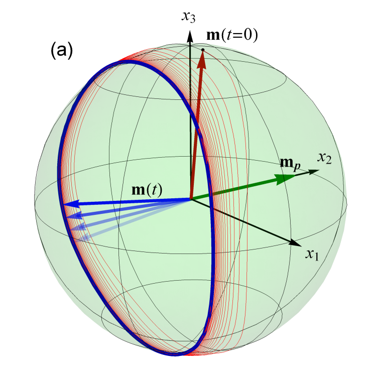
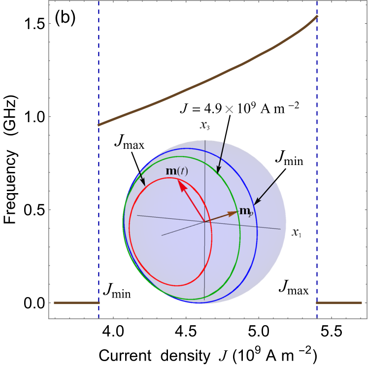
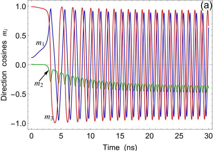
Figure 2 (a) shows the trajectory of the end of the unit vector after the destabilization caused by the positive current with the critical density . Remarkably, the free Co20Fe60B20 layer experiences a dynamic SRT, at which the static magnetic state with almost PP orientation of m transforms into large-angle magnetization precession around in-plane (IP) direction antiparallel to the pinned magnetization Mp. The appearance of such electrically driven SRT can be attributed to the proximity of the free-layer thickness nm to the critical thickness nm, at which the size-induced SRT should take place in the considered MTJ at . Indeed, the change in VCMA promotes voltage-driven SRT to the IP magnetization orientation parallel to the axis, while the STT gives rise to the precession of m. The proximity to the thickness-induced SRT also explains very large precession amplitude at . With increasing current density , the frequency of steady-state magnetization precession rises, whereas its amplitude becomes smaller [Fig. 2(b)]. The precession frequency ranges from 0.95 GHz at to 1.54 GHz at the maximal density A m-2 above which the precession disappears Note1 . Owing to strong STT, the free-layer magnetization stabilizes at along the direction antiparallel to the magnetization of the pinned Co20Fe60B20 layer.
III SPIN AND CHARGE CURRENTS IN NORMAL-METAL OVERLAYER
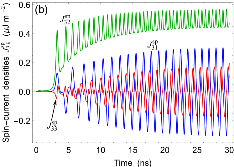
The electrically induced magnetic dynamics in the free Co20Fe60B20 layer should lead to the spin pumping into the Au overlayer. The spin-current density can be specified by a tensor characterizing both the direction of spin flow defined by the unit vector and the orientation of spin polarization Dyakonov1971_459 . Since the Co20Fe60B20 thickness is well above a few monolayer range, the imaginary part of the reflection spin-mixing conductance and the transmission spin mixing conductance are negligible. Therefore, the pumped spin-current density in the vicinity of the Co20Fe60BAu interface can be calculated from the approximate relation Zwierzycki2005_064420 . Adopting for the Co20Fe60BAu interface the theoretical estimate m-2 obtained for the FeAu one Zwierzycki2005_064420 , we calculated the spin current pumped into Au during the magnetization precession in the free layer. Figure 3 shows representative time dependences of the nonzero spin-current densities ( 1, 2, 3), which correspond to the magnetization dynamics appearing at the critical charge-current density . Interestingly, contains significant dc and ac components, whereas and are dominated by the ac component. In the steady-state regime, oscillates with the frequency , which is two times higher than the precession frequency due to similar oscillations of the direction cosine .
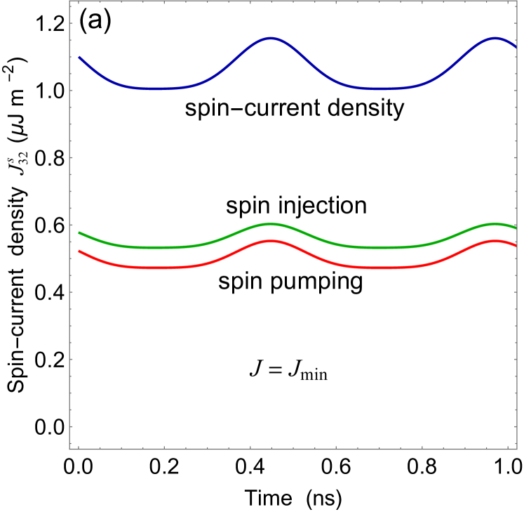
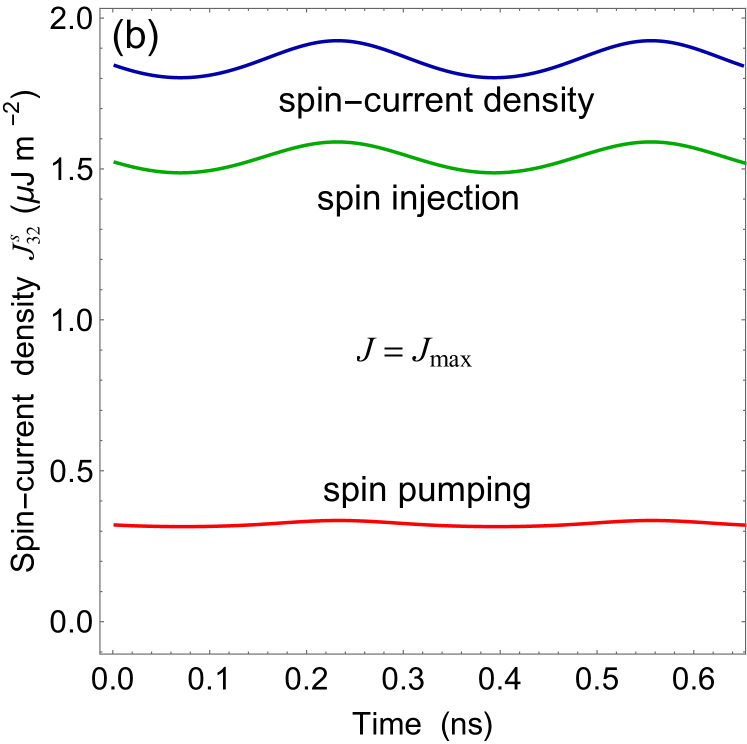
Taking into account the spin polarization of the charge current governed by the free-layer magnetization , we calculated the total spin-current density at the Co20Fe60BAu interface. Figure 4 shows time dependences of the most interesting component evaluated at critical charge-current densities and . Remarkably, the contributions of spin-polarized charge current () and precession-induced spin pumping () have the same sign and phase. At , both and exhibit non-sinusoidal time dependences, whereas at the contribution assumes almost sinusoidal shape while becomes practically constant.
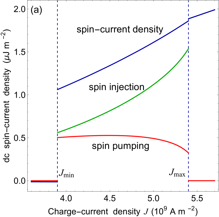
The dc and ac components of the spin-current density in the steady-state regime are plotted in Fig. 5 as a function of the charge-current density . At , the dc component is small and negative due to the charge-current contribution , and the ac component is zero. Within the precession window , grows monotonically with increasing charge current owing to the significant rise of . In contrast, the amplitude of ac component becomes maximal at A m -2 near the middle of the precession window.
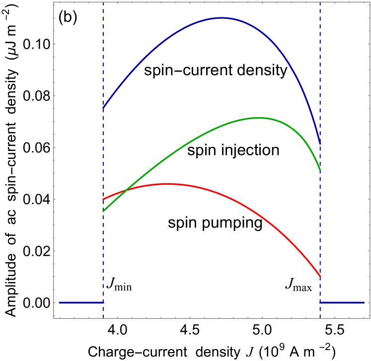
Thus, the Co20Fe60B20/MgO/Co20Fe60B20 tunnel junction excited by a direct charge current can be employed for the generation of spin currents in normal metals Note2 . The power dissipation of such electrically driven spin injector is estimated to be below 40 W which is a very small value for devices with sub-micrometer size Zeng2013_1426 . To evaluate the efficiency of the proposed spin injector, we calculated the electrical potential difference between the lateral sides of the Co20Fe60B20Au bilayer. Owing to the inverse spin Hall effect, the spin flow in the normal metal creates such transverse voltage signal, which can be used to detect this flow experimentally Saitoh2006_182509 .
To determine the distribution of the electric potential in the Co20Fe60B20/Au bilayer, we solved the coupled drift-diffusion equations Dyakonov1971_459 ; Takahashi2003_052409 ; Stiles2004_054408 for charge and spin currents flowing in the Co20Fe60B20 and Au films. The continuity equations for the charge-current density J and the spin-current density have the form of and , where is the charge density, P is the spin polarization density, and is the spin-flip relaxation time. Since spatial variations in the electron concentration n can be neglected for metals Stiles2004_054408 , explicit expressions for the densities J and reduce to
| (4) |
| (5) |
where E is the electric field, is the electron mobility, D is the diffusion coefficient, is the spin Hall angle, denote the components of the Levi-Civita tensor (i, k, l = 1,2,3), and the Einstein summation convention is implied. In Eq. (4), the second term describes the anomalous Hall effect characteristic of ferromagnetic metals, while the third term represents the inverse spin Hall effect. The first term in Eq. (5) gives the contribution of the spin-polarized charge current; the last term accounts for the spin Hall effect, which manifests itself in the current-induced spin accumulation near sample boundaries.
The continuity equations were supplemented by appropriate boundary conditions, which should be fulfilled at the Co20Fe60BAu interface and the outer boundaries of the Co20Fe60B20/Au bilayer connected to a constant-current source via a gold nanoplate (Fig. 1). At the MgOCo20Fe60B20 interface, the projection of the charge current density J on the axis of our reference frame orthogonal to the interface was set equal to the density of the tunnel current. In addition, the vector J was taken to be parallel to the axis near the lateral faces of the Co20Fe60B20/Au bilayer and at the contact with the Au nanoplate, where J satisfies the equality involving the nanoplate thickness d = 5 nm along the axis. At the Co20Fe60BAu interface, we specified the spin-current density via the boundary condition , where is the unit normal vector of the interface, and is the spin polarization of the ferromagnetic layer defined by the densities of states of spin-up () and spin-down () electrons at the Fermi level Huang2008_242509 . Of course, the spin-current direction was taken to be parallel to the lateral faces of the Co20Fe60B20/Au bilayer in the vicinity of these faces.
The sought functions and were calculated numerically by solving the system of differential continuity equations with the aid of a finite-element method. The calculations were performed in the quasistatic approximation (), which is justified by the fact that the period ns of the current-induced magnetization precession is much longer than the characteristic time of charge (0.1 ps Harris1953_1114 ) and spin ( ps Elezzabi1996_3220 ) equilibration. Since the size of the Co20Fe60B20/Au bilayer along the axis is taken to be much smaller than the size along the one (), variations of the potential and the spin polarization density P along the coordinate can be ignored. Therefore, we restricted our numerical calculations to the solution of a two-dimensional problem enabling us to determine the functions and . In addition, only the component of the pumped spin current was taken into account in the calculations, because it was found that the components and have a negligible effect on the sought output voltage of the device. The thickness of Au overlayer along the axis was chosen to be much larger than the Au spin-diffusion length nm Mosendz2010_214403 and set equal to 400 nm.
In the numerical calculations, the conductivity of Co20Fe60B20 was taken to be S m-1 Fan2014_3042 , which yields the electron mobility m-1 V-1 s-1. The anomalous Hall angle and the spin polarization of Co20Fe60B20 were assumed to be 0.02 Zhu2014_202404 and 0.53 Huang2008_242509 , respectively. For Au, the conductivity equals S m-1 Haynes2014 , which gives m2 V-1 s-1 and m2 s-1. The spin-flip relaxation time and the spin Hall angle of Au were taken to be 9.84 ps and 0.0035 Mosendz2010_214403 . It should be noted that the spin polarization density in the free Co20Fe60B20 layer was assumed uniform to ensure consistency with the macrospin approximation used to describe the magnetization dynamics.
Using the obtained functions and , we calculated spatial distributions of the charge-current density in the Co20Fe60B20/Au bilayer and the electrical potential difference between its lateral sides. Interestingly, the charge-current distribution at any fixed moment t can be represented as a sum of the applied uniform current and a vortex-like contribution illustrated by Fig. 6. The transverse voltage signal generated by the device decreases with increasing distance from the MgOCo20Fe60B20 interface, falling rapidly within the Co20Fe60B20 layer [Fig. 7(a)].
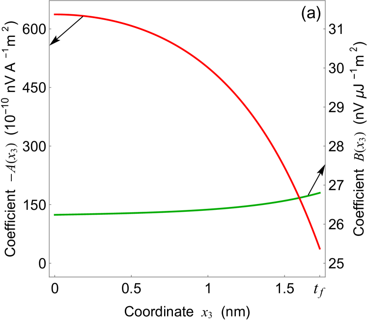
Remarkably, the analysis of the numerical results obtained for the transverse voltage reveals that can be fitted with a high accuracy by the analytical formula
| (6) |
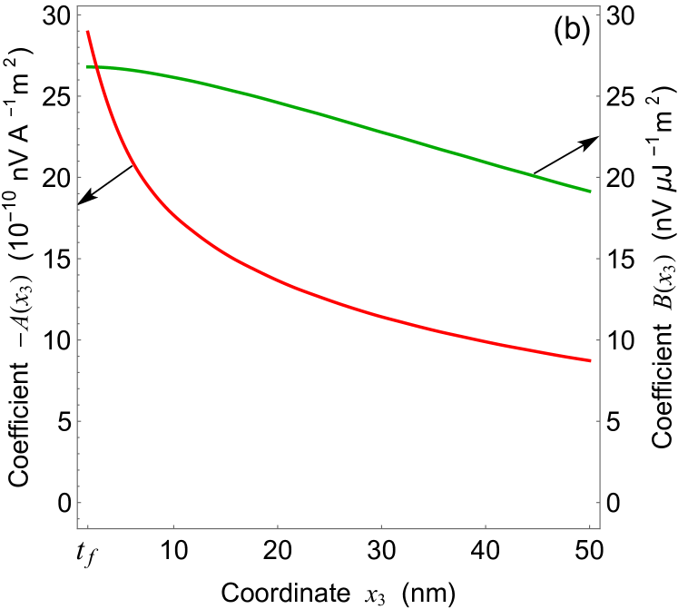
where the first term represents the contribution of the anomalous Hall effect, while the second term describes the contribution resulting from the inverse spin Hall effect. Since the coefficients and involved in Eq. (6) have very different dependences on the distance (see Fig. 8), the ratio changes strongly across the Co20Fe60BAu interface. Figure 9 demonstrates that this ratio is mostly very small inside the Co20Fe60B20 layer, but rises steeply near the Co20Fe60BAu interface and exceeds 5 in the Au layer. Hence, measurements of the average voltage signal created by the Co20Fe60B20 layer provide information on the anomalous Hall effect, whereas the potential difference between the faces of the Au layer measured at nm characterizes the inverse spin Hall effect.
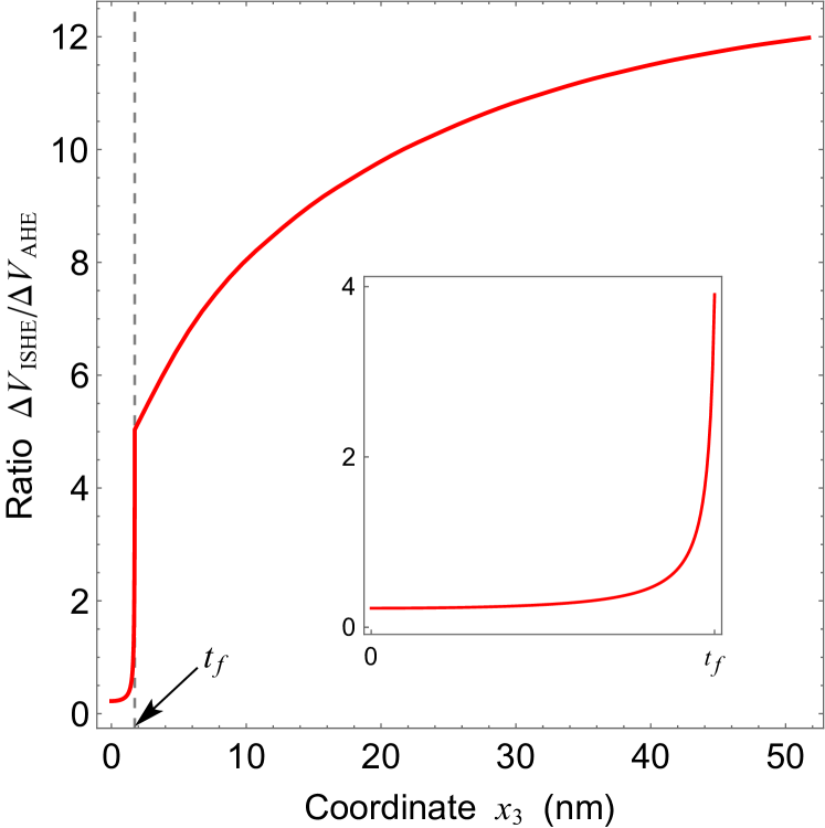
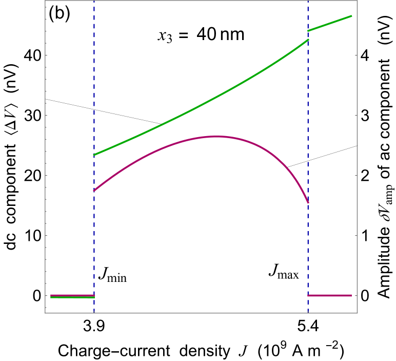
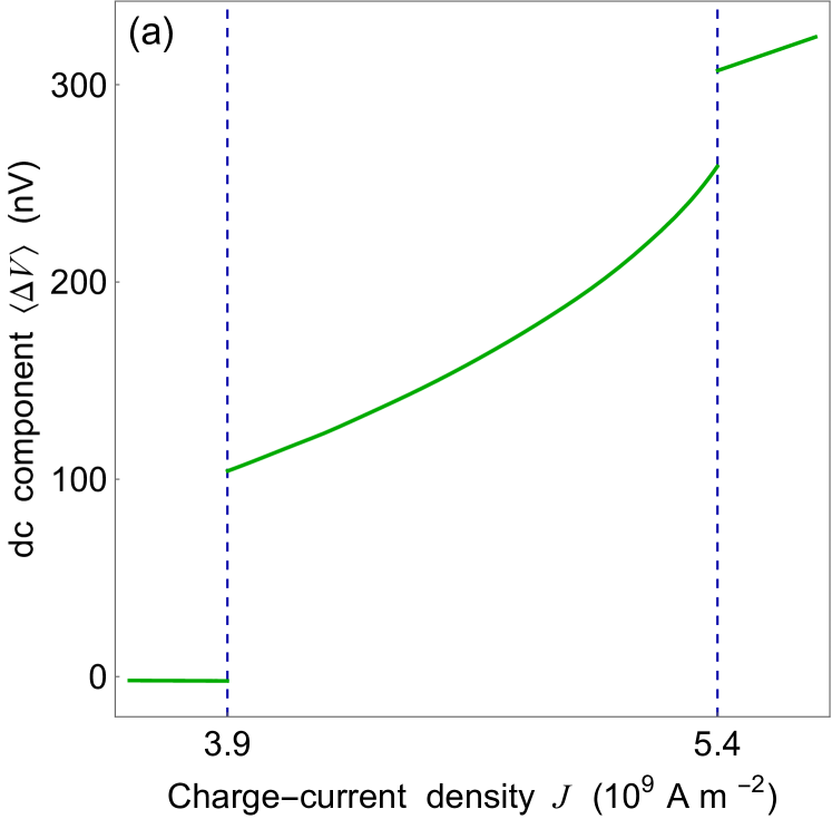
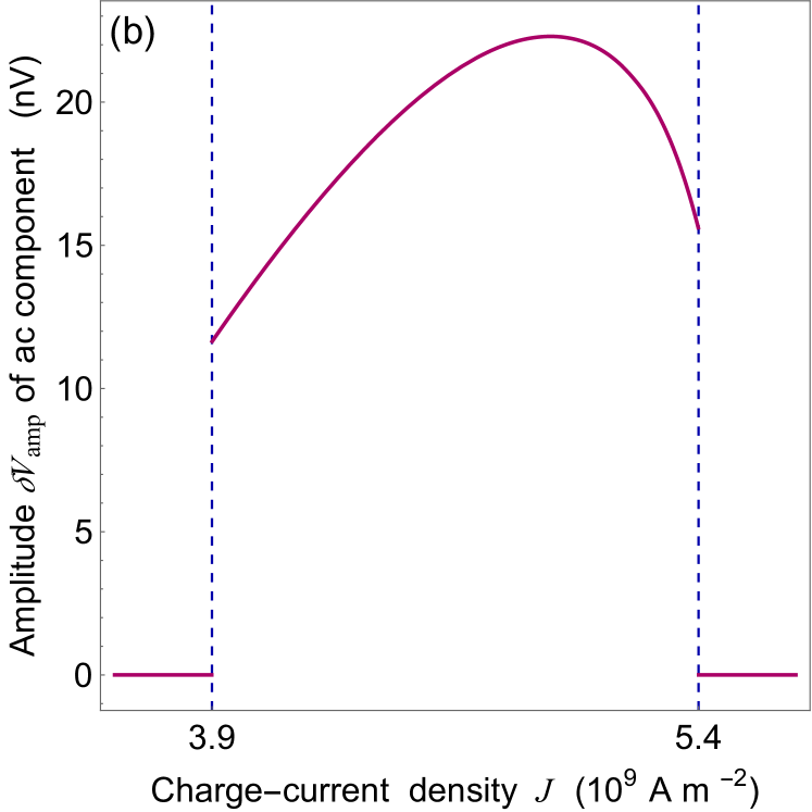
Figure 10 shows how the dc and ac components of the transverse signal averaged over the thickness of the Co20Fe60B20 layer vary with the charge-current density J. It can be seen that the curves are similar to the dependences presented in Fig. 5, which describe the spin injection into Au caused by the spin-polarized charge current. In contrast, Fig. 7(b) demonstrates the dc component and the amplitude of the GHz-frequency ac component calculated at nm. Importantly, both the dc and microwave signals appear to be large enough for the experimental detection within the precession window. Moreover, the dependences and repeat the graphs shown in Fig. 5 for the total spin-current density generated at the AuCo20Fe60B20 interface, differing by a constant factor of 20.61 nV J-1 m2 only. Hence the measurements of by nanocontacts placed at distances from the boundary of ferromagnetic layer provide information on the spin injection into the normal metal.
IV SUMMARY
In summary, we presented a comprehensive theoretical study of the spin dynamics and charge transport in the Co20Fe60B20/MgO/Co20Fe60B20/Au tunneling heterostructure connected to a constant-current source. The performed numerical calculations enabled us to find the range of current densities, within which electrically driven magnetization precession appears in the free Co20Fe60B20 layer, and to determine the precession frequencies and trajectories. Remarkably, a novel, dynamic SRT has been predicted, which is caused by the joint impact of STT and VCMA and has the form of magnetization reorientation between initial static direction and final dynamic precessional state. The results obtained for the magnetization dynamics were then used to evaluate the dc and ac components of the spin current generated in the Au overlayer owing to the precession-driven spin pumping and the oscillating spin polarization of the charge current. Taking into account the inverse spin Hall effects and anomalous Hall effects, we finally calculated the charge flow and electric-potential distribution in the Co20Fe60B20/Au bilayer via the numerical solution of coupled drift-diffusion equations for charge and spin currents. It is shown that the potential difference between the lateral faces of the Au layer is large enough for experimental detection, which demonstrates significant efficiency of the described spin injector.
ACKNOWLEDGMENTS
The work was supported by the Foundation for the Advancement of Theoretical Physics and Mathematics ”BASIS”.
References
- (1) J. C. Slonczewski, Phys. Rev. B 39, 6995 (1989).
- (2) J. C. Slonczewski and J. Z. Sun, J. Magn. Magn. Mater. 310, 169 (2007).
- (3) S. I. Kiselev, J. C. Sankey, I. N. Krivorotov, N. C. Emley, R. J. Schoelkopf, R. A. Buhrman, and D. C. Ralph, Nature (London) 425, 380 (2003).
- (4) W. H. Rippard, M. R. Pufall, S. Kaka, S. E. Russek, and T. J. Silva, Phys. Rev. Lett. 92, 027201 (2004).
- (5) A. A. Tulapurkar, Y. Suzuki, A. Fukushima, H. Kubota, H. Maehara, K. Tsunekawa, D. D. Djayaprawira, N. Watanabe, and S. Yuasa, Nature 438, 339 (2005).
- (6) J. C. Sankey, P. M. Braganca, A. G. F. Garcia, I. N. Krivorotov, R. A. Buhrman, and D. C. Ralph, Phys. Rev. Lett. 96, 227601 (2006).
- (7) M. Deac, A. Fukushima, H. Kubota, H. Maehara, Y. Suzuki, S. Yuasa, Y. Nagamine, K. Tsunekawa, D. D. Djayaprawira, and N. Watanabe, Nat. Phys. 4, 803 (2008).
- (8) S. Bonetti, P. Muduli, F. Mancoff, and J. Åkerman, Appl. Phys. Lett. 94, 102507 (2009).
- (9) P. M. Braganca, O. J. Lee, O. Ozatay, L. Liu, G. Finocchio, D. C. Ralph, and R. A. Buhrman, Appl. Phys. Lett. 102, 252402 (2013).
- (10) Z. Zeng, G. Finocchio, B. Zhang, P. K. Amiri, J. A. Katine, I. N. Krivorotov, Y. Huai, J. Langer, B. Azzerboni, K. L. Wang, and H. Jiang, Sci. Rep. 3, 1426 (2013).
- (11) B. Fang, M. Carpentieri, X. Hao, H. Jiang, J. A. Katine, I. N. Krivorotov, B. Ocker, J. Langer, K. L. Wang, B. Zhang, B. Azzerboni, P. K. Amiri, G. Finocchio, and Z. Zeng, Nat. Comms. 7, 11259 (2016).
- (12) E. B. Myers, D. C. Ralph, J. A. Katine, R. N. Louie, and R. A. Buhrman, Science 285, 867 (1999).
- (13) J. A. Katine, F. J. Albert, R. A. Buhrman, E. B. Myers, and D. C. Ralph, Phys. Rev. Lett. 84, 3149 (2000).
- (14) Y. Huai, F. Albert, P. Nguyen, M. Pakala, and T. Valet, Appl. Phys. Lett. 84, 3118 (2004).
- (15) G. D. Fuchs, N. C. Emley, I. N. Krivorotov, P.M. Braganca, E. M. Ryan, S. I. Kiselev, J. C. Sankey, D. C. Ralph, R. A. Buhrman, and J. A. Katine, Appl. Phys. Lett. 85, 1205 (2004).
- (16) H. Sato, M. Yamanouchi, K. Miura, S. Ikeda, H. D. Gan, K. Mizunuma, R. Koizumi, F. Matsukura, and H. Ohno, Appl. Phys. Lett. 99, 042501 (2011).
- (17) S. Ikeda, J. Hayakawa, Y. M. Lee, F. Matsukura, Y. Ohno, T. Hanyu, and H. Ohno, IEEE Trans. Electron Devices 54, 991 (2007).
- (18) N. A. Pertsev and H. Kohlstedt, Adv. Funct. Mater. 22, 4696 (2012).
- (19) K. Ando, S. Fujita, J. Ito, S. Yuasa, Y. Suzuki, Y. Nakatani, T. Miyazaki, and H. Yoda, J. Appl. Phys. 115, 172607 (2014).
- (20) M. Weisheit, S. Fähler, A. Marty, Y. Souche, C. Poinsignon, and D. Givord, Science 315, 349 (2007).
- (21) C.-G. Duan, J. P. Velev, R. F. Sabirianov, Z. Zhu, J. Chu, S. S. Jaswal, and E. Tsymbal, Phys. Rev. Lett. 101, 137201 (2008).
- (22) T. Maruyama, Y. Shiota, T. Nozaki, K. Ohta, N. Toda, M. Mizuguchi, A. A. Tulapurkar, T. Shinjo, M. Shiraishi, S. Mizukami, Y. Ando, and Y. Suzuki, Nat. Nanotechnol. 4, 158 (2009).
- (23) K. Nakamura, R. Shimabukuro, Y. Fujiwara, T. Akiyama, T. Ito, and A. J. Freeman, Phys. Rev. Lett. 102, 187201 (2009).
- (24) M. K. Niranjan, C.-G. Duan, S. S. Jaswal, and E. Y. Tsymbal, Appl. Phys. Lett. 96, 222504 (2010).
- (25) W.-G. Wang, M. Li, S. Hageman and C. L. Chien, Nature Mater. 11, 64 (2011).
- (26) S. Kanai, M. Yamanouchi, S. Ikeda, Y. Nakatani, F. Matsukura, and H. Ohno, Appl. Phys. Lett. 101, 122403 (2012).
- (27) J. G. Alzate, P. K. Amiri, G. Yu, P. Upadhyaya, J. A. Katine, J. Langer, B. Ocker, I. N. Krivorotov, and K. L. Wang, Appl. Phys. Lett. 104, 112410 (2014).
- (28) T. Nozaki, Y. Shiota, S. Miwa, S. Murakami, F. Bonell, S. Ishibashi, H. Kubota, K. Yakushiji, T. Saruya, A. Fukushima, S. Yuasa, T. Shinjo, and Y. Suzuki, Nat. Phys. 8, 491 (2012).
- (29) J. Zhu, J. A. Katine, G. E. Rowlands, Y.-J. Chen, Z. Duan, J. G. Alzate, P. Upadhyaya, J. Langer, P. K. Amiri, K. L. Wang, and I. N. Krivorotov, Phys. Rev. Lett. 108, 197203 (2012).
- (30) G. Viaud and N. A. Pertsev, Phys. Rev. B 90, 064429 (2014).
- (31) K. Miura, S. Yabuuchi, M. Yamada, M. Ichimura, B. Rana, S. Ogawa, H. Takahashi, Y. Fukuma, and Y. Otani, Sci. Rep. 7, 42511 (2017).
- (32) C.-G. Duan, J. P.Velev, R. F. Sabirianov, W. N. Mei, S. S. Jaswal, and E. Y. Tsymbal, Appl. Phys. Lett. 92, 122905 (2008).
- (33) Y. Shiota, T. Maruyama, T. Nozaki, T. Shinjo, M. Shiraishi and Y. Suzuki, Appl. Phys. Exp. 2, 063001 (2009).
- (34) N. A. Pertsev, Sci. Rep. 3, 2757 (2013).
- (35) N. A. Pertsev, G. Viaud, and B. Dkhil, Phys. Rev. B 90, 024426 (2014).
- (36) Y. Shiota, T. Nozaki, F. Bonell, S. Murakami, T. Shinjo, and Y. Suzuki, Nat. Mater. 11, 39 (2012)
- (37) C. Grezes, F. Ebrahimi, J. G. Alzate, X. Cai, J. A. Katine, J. Langer, B. Ocker, P. K. Amiri, and K. L. Wang, Appl. Phys. Lett. 108, 012403 (2016).
- (38) Y. Tserkovnyak, A. Brataas, and G. E. W. Bauer, Phys. Rev. Lett. 88, 117601 (2002).
- (39) Y. Tserkovnyak, A. Brataas, G. E. W. Bauer, and B. I. Halperin, Phys. Rev. B 66, 060404(R) (2002).
- (40) E. Saitoh, M. Ueda, H. Miyajima, and G. Tatara, Appl. Phys. Lett. 88, 182509 (2006).
- (41) O. Mosendz, V. Vlaminck, J. E. Pearson, F. Y. Fradin, G. E. W. Bauer, S. D. Bader, and A. Hoffmann, Phys. Rev. B 82, 214403 (2010).
- (42) K. Ando, S. Takahashi, J. Ieda, H. Kurebayashi, T. Trypiniotis, C. H. W. Barnes, S. Maekawa, and E. Saitoh, Nat. Mater. 10, 655 (2011).
- (43) S. Ikeda, K. Miura, H. Yamamoto, K. Mizunuma, H. D. Gan, M. Endo, S. Kanai, J. Hayakawa, F. Matsukura, and H. Ohno, . Mater. 9, 721 (2010).
- (44) A. Brataas, A. D. Kent, and H. Ohno, Nat. Mater. 11, 372 (2012).
- (45) M. Zwierzycki, Y. Tserkovnyak, P. J. Kelly, A. Brataas, and G. E. W. Bauer, Phys. Rev. B 71, 064420 (2005).
- (46) A. Slavin and V. Tiberkevich, IEEE Trans. Magn. 45, 1875 (2009).
- (47) A. Aharoni, J. Appl. Phys. 83, 3432 (1998).
- (48) W. Skowronski, T. Stobiecki, J. Wrona, K. Rott, A. Thomas, G. Reiss, and S. van Dijken, J. Appl. Phys. 107, 093917 (2010).
- (49) K. Lee, J. J. Sapan, S. H. Kang, and E. E. Fullerton, J. Appl. Phys. 109, 123910 (2011).
- (50) R. C. Hall, J. Appl. Phys. 31, S157 (1960).
- (51) K. Tsunekawa, M. Nagai, H. Maehara, S. Yamagata, D. D. Djayaprawira, N. Watanabe, S. Yuasa, Y. Suzuki, and K. Ando, presented at the International Magnetics Conference, Nagoya, Japan, Apr. 2005, Paper FB-05.
- (52) Our theoretical predictions concerning monotonic rise of the precession frequency with increasing current density and strong decrease of the critical current density at the free-layer thicknesses approaching the SRT thickness agree with the experimental data
- (53) M. I. Dyakonov and V. I. Perel, Phys. Lett. A 35, 459 (1971).
- (54) Simulations with a random torque emulating thermal noise showed that thermal fluctuations can only reduce the critical current density necessary to initiate the magnetization precession, which appears to be very stable against orientational fluctuations caused by the thermal noise. Hence, the functioning of the described spin injector should be essentially unaffected by the thermal fluctuations.
- (55) S. Takahashi and S. Maekawa, Phys. Rev. B 67, 052409 (2003).
- (56) M. D. Stiles, J. Xiao, and A. Zangwill, Phys. Rev. B 69, 054408 (2004).
- (57) S. X. Huang, T. Y. Chen, and C. L. Chien, Appl. Phys. Lett. 92, 242509 (2008).
- (58) L. Harris and A. L. Loeb, J. Opt. Soc. Am. 43, 1114 (1953).
- (59) A. Y. Elezzabi, M. R. Freeman, and M. Johnson, Phys. Rev. Lett. 77, 3220 (1996).
- (60) X. Fan, H. Celik, J. Wu, C. Ni, K.-J. Lee, V. O. Lorenz, and J. Q. Xiao, Nat. Comms. 5, 3042 (2014).
- (61) T. Zhu, P. Chen, Q. H. Zhang, R. C. Yu, and B. G. Liu, Appl. Phys. Lett. 104, 202404 (2014).
- (62) W. M. Haynes, CRC Handbook of Chemistry and Physics, 95th ed. (CRC Press, Boca Raton, FL, 2014).