An alternative approach to populate and study the 229Th nuclear clock isomer
Abstract
A new approach to observe the radiative decay of the 229Th nuclear isomer, and to determine its energy and radiative lifetime, is presented. Situated at a uniquely low excitation energy, this nuclear state might be a key ingredient for the development of a nuclear clock, a nuclear laser and the search for time variations of the fundamental constants. The isomer’s decay towards the ground state will be studied with a high-resolution VUV spectrometer after its production by the decay of 229Ac. The novel production method presents a number of advantages asserting its competitive nature with respect to the commonly used 233U -decay recoil source. In this paper, a feasibility analysis of this new concept, and an experimental investigation of its key ingredients, using a pure 229Ac ion beam produced at the ISOLDE radioactive beam facility, is reported.
I Introduction
In 1976, experimental evidence was reported pointing to a low-lying nuclear state in the 229Th isotope at an excitation energy, E, below eV Kroger and Reich (1976). Subsequent experiments lowered the predicted excitation energy of this 229Th isomer down to the eV range, which is unique on the nuclear chart Burke et al. (2008); Gulda et al. (2002); Canty et al. (1977); Bemis et al. (1988); Barci et al. (2003); Ruchowska et al. (2006); Reich and Helmer (1990); Helmer and Reich (1994); Irwin and Kim (1997). This exeptionally low excitation energy of the isomer initiated numerous research projects aimed at unveiling its characteristics. In the last decade, breakthrough experiments offered a proof of its existence, studied the isomer’s nuclear moments and provided confirmation of an excitation energy in the VUV part of the spectrum (E eV) Beck et al. (2007, 2009); Wense et al. (2016); Thielking et al. (2018). The available experimental data on the isomer in 229Th are summarized in fig. 1. The main feature of this isomer, its low excitation energy, promises a range of future applications which rely on the extension of laser manipulation techniques from the electron shell towards the nuclear domain, more specifically: a direct VUV laser excitation of a nuclear transition could be within reach for the first time. In addition to the creation of a nuclear clock, matching or even exceeding the performance of present day atomic clocks, this isomeric nuclear state could be decisive in the development of the first nuclear laser and more fundamentally; in the study of the time dependence of fundamental constants of nature Peik and Tamm (2003); Peik and Okhapkin (2015); Campbell et al. (2012); Berengut et al. (2009); Tkalya (2011).
Working towards a laser excitation of a nuclear transition, fulfilling the isomer’s potential, requires, however, improvement in the precision and accuracy of both excitation-energy and unknown radiative-lifetime observables. The present-day accepted value places the isomer’s excitation energy at E eV. This value was obtained through indirect high-resolution -spectroscopy data of inter- and intraband transitions in ground- and isomeric state collective bands Beck et al. (2007). The large experimental uncertainty of 0.5 eV (corresponding to nm or THz) in combination with an expected narrow nuclear resonance of Hz, presents a practical stumbling block for the direct excitation of this nuclear transition using coherent light sources. Moreover, recent studies shed doubt on the accuracy of the current excitation energy Tkalya et al. (2015). To improve both the accuracy and the precision of the isomer’s key observables, a variety of physics techniques are implemented, with one branch focusing on a direct measurement of the electromagnetic deexcitation of Th embedded in a host material.
To study and detect the VUV photons originating from the Th-229Th transition, the decay of 233U (T years) is frequently used to populate the isomer Beck et al. (2007); Wense et al. (2016); Zhao et al. (2012); Stellmer et al. (2016). With a probability of 2% per decay, 233U decays to Th, whose 84 keV recoil energy is thermalized in a gas or solid host after which its decay products can be scrutinized. Due to the unusually low excitation energy, the electromagnetic environment where the isomer is finally situated, determines its decay mode. In case the thorium electrons have a free quantum state available at an energy equal to E above its current state, satisfying conservation of energy, the isomer’s dominant decay channel is internal conversion (IC). A half-life of T s was reported for this decay channel when the isomer was deposited on the surface of a Multi-Channel Plate (MCP) detector Wense et al. (2016). In the other case, nuclear decay will persist, albeit with a much longer lifetime, Seiferle et al. (2017). This rare feature allows a certain freedom in tuning the environment to select the favored decay mode. However, at the same time, it requires sufficient understanding of the Th electromagnetic environment.
In this paper, a novel approach to observe the radiative decay and to measure the radiative energy and lifetime of Th is described. It is based on an alternative production method, whereby the isomer is populated via the decay of 229Ac, produced online. VUV spectroscopy is then performed after implantation of 229Ac in a large band gap crystal (E E, to block the IC channel), where it decays to Th. In the next section, a detailed comparison between the aforementioned production methods will be presented, in line with the goals of the proposed experiment. The feasibility of the proposed experiment will then be outlined in section III. Three preparatory experiments have been conducted and reported in sections IV-V-VI-VII together with some preliminary results. First, the ability to produce an intense beams of actinium ions was verified at ISOLDE, CERN, for the first time (see section IV). Second, as a key performance indicator of 229Ac for producing the isomer, an attempt was made to measure the true total feeding probability, 229AcTh (see section V-VI). Finally, the lattice positions of the 229Ac atoms, after implantation in a CaF2 host, were studied (see section VII).
II The decay of 229Ac
To produce Th via radioactive decay, three methods exist: decay from the 233U (T years) mother nucleus, electron capture decay from 229Pa (T days) and decay from 229Ac (T1/2 = 62.7 min). The 233U source has been used extensively as means to produce the isomer, also when aiming at a direct decay measurement of the low-energy photons. However, some aspects of this production method can be brought forward as possible reasons for the absence of conclusive results. The 233U radioactive decay produces energetic particles ( MeV). The background signal that these particles induce through radioluminescence in the host structure, is a strong competitor for the isomeric decay signal, which is, additionally, hampered by the small 2% branching ratio Wense et al. (2018). Next, absorbing the keV recoil energy of the Th particles in the host material will cause local pockets of lattice damage close to the unknown point of arrival. As the large bandgap of the host crystal is essential for the radiative decay of the isomer to happen, this structural damage and the unknown stopping point of the isomer after implantation could induce new levels in the band gap, restricting the ability of the host to suppress the IC channel.
As an alternative to 233U, 229Pa and 229Ac exist. Both isotopes suffer from low production yields, although renewed interest can be found in 229Pa. Only recently, an efficient way of producing 229Ac, online, was reported Ferrer et al. (2017). It enables to study Th with intense beams of 229Ac, for which the decay presents a number of key advantages in comparison to the 233U decay. A summary of the decay characteristics of 229Ac is given in fig. 1. The advantages can be listed as follows:
-
•
The online production in a UCx target via a laser ion source at ISOLDE, CERN, using a proven ionization scheme, will provide an intense and pure source of 229Ac (section IV).
- •
-
•
The decay of 229Ac provides an almost recoil free (E 2 eV) Th production, locking Th in the place of implantation, establishing an unchanged band gap.
-
•
The particles, emerging after the 229Ac decay, are likely to produce a significantly lower radioluminescence in comparison with the high stopping power particles and the recoiling 229Th nucleus, both emerging after 233U decay.
- •
The advantages of using 229Ac decay over 233U decay are explained in detail below. First, an indirect -decay branching ratio of at least 14% towards the isomer in the 229Th daughter has been experimentally determined NNDC . This presents only a lower limit for the feeding probability towards the isomer, because, per decay, a probability of 79% exists for the decay path to go towards the 229Th isomer or ground state directly, indistinguishable in these data. The feeding probability should, therefore, lie in the region 14% 93%. An experiment to determine this probability will be outlined in section V. Second, after the 229Ac decay, the 229Th nuclei experience a maximum recoil energy of only eV Kofoed-Hansen (1948), which is around an order of magnitude smaller than the typical displacement energies in a crystal lattice . Therefore, it is expected that after implantation, both 229Ac and its daughter 229Th reside in the same position on the crystal lattice. This assumption drastically simplifies an accurate understanding of the electromagnetic environment of the isomer, as the 2.3 eV recoil energy does not induce any additional damage to the lattice. An experiment, aiming for an accurate determination of the isomer’s position in the host’s lattice, will be discussed in section VII. Third, when implanting 229Ac in a crystal host, the emitted particles will result in a lower radiatively-induced background. The particle stopping power is around three orders of magnitude lower than that for ’s and much lower than that of the recoiling nuclei. Finally, in case the aforementioned experiment shows an unfavorable lattice location of the isomeric nuclei, one where E E is not fulfilled, the lifetime of the 229Ac isotope allows for host annealing to be done after implantation. In this way, the probability of a favorable lattice site occupation can be increased Pereira et al. (2011). In combination, these numbers present an increase of at least a factor seven of the signal-to-noise ratio in comparison to the conventional 233U production method, potentially further enlarged by the unknown total feeding probability, as well as better control of the lattice occupation and a reduction of the radioluminescence background signal that will be quantified in the next section.

III Quantitative analysis of the VUV spectroscopy concept
The proposed experiment to study Th, produced online via 229Ac, will consist of two main components. First of all, the 30 keV 229Ac ion beam will be implanted in the bulk of a thin large-bandgap host crystal. The reduced thickness of the sample will minimize the background (see below), while, more importantly, the large band gap inhibits the IC decay channel of the isomer. Multiple options for the host crystal exist, such as CaF2, MgF2, Na2ThF6, LiCaAlF6, LiSrAlF6, YLIF4 and more exotic, frozen noble gases Hehlen et al. (2013); Van der Heyden et al. (1987). For the purpose of this paper, CaF2 is selected, presenting a band gap of 11.6-12.1 eV Dessovic et al. (2014). 229Ac ions implanted in CaF2 at 30 keV, have a projected range of 18.2 nm with a straggling of 3.5 nm. Depending on the outcome of the implantation studies of 229Ac in CaF2 (see section VII), the implantation period of around two 229Ac half-lives ( 2 hours), can be followed by in situ annealing procedures. In the second part of the experiment, the crystal will be moved to the spectrometer port, where the low energy photons of the Th-229Th transition will be studied by a VUV spectrometer (e.g. Resonance VM92). This device delivers a spectral resolution better than 1 nm with a 150 m slit, standard grating of 1800 grooves/mm, f number of 2.2 and a grating efficiency 15 in combination with tailored entrance optics, cooled electronics and an MCP-based detection setup. A spectral resolution of 0.1 nm is within reach after decreasing the slit’s dimensions, at the cost of efficiency. During detection, a second foil will be irradiated with the 229Ac beam simultaneously to minimize duty cycle losses of the online beam time.
In order to quantify the expected signal strength at the Th-229Th photon energy, a detailed feasibility analysis can be done. Based on theoretical cross sections for 1.4 GeV protons impinging on a 238UCx target at the ISOLDE facility of CERN, a 229Ac ion beam intensity of 107 pps (see section IV) is estimated. In the aforementioned measuring cycle with a detection time of 3 h, and an assumed 1 h radiative half-life of the isomer, approximately 3105 VUV photons s-1 are to be expected from the isomeric decay, considering a conservative feeding of only 14 (this number represents an average over the 3 h of detection time). This number can be compared to the expected photon rates from Th ions, produced by 233U, recoiling from a thin foil ( 150 s-1), from a 1 cm3 233U-doped CaF2 crystal (4104 s-1) or using synchrotron radiation to excite 229Th-doped crystals (106 s-1) Hehlen et al. (2013). The total VUV detection efficiency considers the geometrical efficiency of the entrance slit, the acceptance solid angle of the spectrometer, the efficiency of the grating and the quantum efficiency of the CCD camera setup, adding to a total efficiency of 0.003%. Taking this number into account, the isomer decay signal should correspond to a total of around 9 cps situated in the range 159(10) nm, see table 1. The most significant background-signal contributions, detected in the MCP detector, are divided in three categories. First, the detection of primary radiation from the decay of 229Ac and its daughters is minimized due to passive radiation shielding and the limited measuring time on each implantation foil. Second, the radioluminescence of the decay products of 229Ac is to be considered. When fully stopped, the 5 MeV particles emerging from the decay of 229Th release a total of around 104 photons. By limiting the CaF2 layer to a thickness of 50 nm, the particles will only lose around 10 keV leading to a total detection rate smaller than 10 cps at the detector during the decay cycle, predominantly in the spectral region above 200 nm. A similar story holds for the signal due to radioluminescence from the particles, which, in the region below 200 nm, is predominantly owing to Cerenkov radiation. Only losing about 10 eV in the 50 nm implantation foil, this specific background rate should be below cps at the detector site Stellmer et al. (2016, 2015). Finally, the ISOLDE facility provides the opportunity to run the experiment with other actinium isotopes. In combination with the possibility to check the obtained signal with the lasers of the ISOLDE ion source on/off (see section IV), these extra measures should deliver key advantages in characterizing the background signal in a reproducible way.
| Description | Estimate |
|---|---|
| 229Ac beam intensity (pps) | |
| 229Ac atoms implanted in 2h | |
| 229Ac atoms after 2h implantation | |
| Isomeric decays in 3h | |
| VUV photon rate (cps) | |
| Radioluminescence background | |
| (229Ac decay) (cps) | |
| Radioluminescence background | |
| (229Th decay) (cps) |
IV The production of 229Ac at ISOLDE, CERN
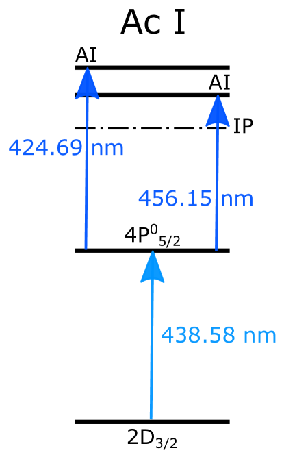
To allow for a high intensity, pure 229Ac source, the described experiments take place at the ISOLDE facility in CERN, Geneva Borge and Jonson (2017). In this radioactive ion beam facility, protons at an energy of 1.4 GeV, and an average current of 2 A, produced by CERN’s PS-Booster proton accelerator, irradiate a thick (100 g/cm2) 238UCx target heated to about 2000∘C. The nuclear reaction products which arise from these energetic collisions are extracted from a hot target, predominantly in a neutral atomic state, via diffusion and effusion into an ionization cavity. Subsequently, they are ionized, mainly via laser resonant ionization Fedosseev et al. (2017), increasing the total yield and beam purity significantly. After laser ionization, the ions are extracted and accelerated to 30 kV, mass separated and sent to different experiments. Recently, a number of efficient laser ionization schemes for actinium isotopes are developed Raeder et al. (2013); Ferrer et al. (2017). The two laser schemes used to produce actinium ions for the experiments discussed in sections V and VII are shown in fig. 2. Ionization with either 424.69 nm or 456.15 nm revealed similar ionization efficiency, resulting in a laser-ionized 227Ac production rate of about pps as measured at a Faraday cup in the focal plane of the separator. Based on a calculated cross section for the 229Ac isotope, 1.2 particles/A are produced in a typical 238UCx target (the yield could be increased by an order of magnitude when using a 232Th target Armbruster et al. (2004)). Within conservative estimates, the laser ion source at ISOLDE, aiming for the known Ac laser ionization scheme of fig. 2, should be capable of producing 229Ac beams of around 107 pps, delivered in a spot of diameter 4 mm. Due to suboptimal ion transport conditions, caused by technical problems in the ISOLDE separator, a production rate of about 106 particles s-1 was observed at the branching ratio setup (discussed in section V), for the specific isotope 229Ac. Through the combination of the known Ac ionization scheme and the ISOLDE facility, it is possible to produce isotopically-pure, high-intensity beams of 229Ac via laser resonant ionization techniques in an online facility, opening the door for the exploitation of the 229Ac isotope as a viable source of the isomer in 229Th.
V Branching ratio measurement
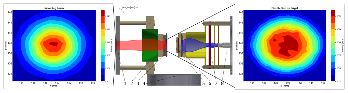
One key feature of the new approach to study the 229Th isomer is its expected strong feeding in the decay of 229Ac. To measure the unknown total branching ratio towards the isomer, a dedicated setup detecting the isomeric decay via its low-energy IC electrons in time-delayed coincidence with the decay of the actinium mother nucleus has been developed, see fig. 3. Differentiating the low-energy internal conversion electrons stemming from the decay of the isomer from other low-energy electrons (e.g. and radiation-induced secondary electrons and conversion electrons from higher lying states in ) is based on the time-dependence of the signal. Where the former shows an exponential decay with a half-life of s, the latter is of prompt nature within a time window of 500 ns. The experimentally determined half-life of s, however, is expected to be dependent on the chemical environment of the isomer, which will be different for the present experiment. The setup in fig. 3 consists of two components. First, the radioactive ion beam will be implanted in a suitable host material. This host is chosen such that after -decay the chemical environment around the thorium dopant favors the IC decay channel of the isomer over the radiative one in order to take advantage of the shorter lifetime () of this channel and the efficient detection of low-energy electrons Seiferle et al. (2017). Internal conversion will take place if the electromagnetic environment allows the excitation of surrounding electrons with the isomeric energy E. This condition is easily fulfilled in metallic hosts, where a continuous distribution of electronic quantum states, referred to as Density of States (DOS), without any intermittent bandgap is available. Finally, the setup consists of a rotatable target holder with a thin metallic foil (25 m) as implantation host material, which can be lifted, turned and positioned from the low-energy implantation site to a detection site where the time-delayed coincidences will be performed (see central part of fig. 3).
In order for the low-energy IC electrons to escape from the host material, the actinium dopant must be implanted close to the metal/host surface. To accomplish this, the highly energetic actinium ions, which are delivered to the implantation section of the setup, first encounter a deceleration electrode of parabolic shape which can decelerate the radioactive ion beam to a few hundreds of eV and focus it on the target to obtain a shallow implantation profile (see left and right fig. 3). The design has been optimized for an efficient deposition of actinium within a spot of 20 mm diameter on the target, using the SIMION electrostatic solver and ion trajectory simulator Dahl (2000). A typical beam with 30 mm mrad emittance and a Gaussian spatial distribution of 7 mm full-width-at-half-maximum at 30 keV energy passes a diaphragm with 20 mm inner diameter at the entrance to the setup. The voltage of the deceleration electrode (typically 1-3 kV below the target voltage) is tuned to obtain optimal focusing of the decelerated beam on the target. The simulation shows that with this conservative estimate of typical beam parameters at ISOLDE and a correctly aligned beam, efficiencies of 95 or higher at implantation energies of 100 eV are obtained. The magnitude of the deceleration electrode’s dimensions and the large target size make the design less sensitive to deviations of the incoming actinium ion beam with respect to the central axis. Higher implantation energies decrease this sensitivity even further but reduce at the same time the detection efficiency of low-energy conversion electrons stemming from the isomeric decay as outlined in the next section.
After an implantation period of approximately one half-life, the target is rotated towards the detection section. radiation emitted in the decay of is registered by a passivated implanted planar silicon detector (PIPS, Mirion 30X30500eb). radiation can be detected using a 70 relative efficiency high-purity germanium detector (Canberra HPGe 88045). IC electrons leaving the bulk of the target are accelerated by a 4 kV electrode and guided towards a channeltron detector (Sjuts KBL10RS). The germanium, silicon and channeltron detector signals are recorded on an event-by-event basis together with an absolute time stamp and the signals of time-to-amplitude converters. This time information will be used to discriminate between signals in the channeltron from secondary electrons produced by - and radiation and direct radiation. Secondary electrons created by - and radiation are expected to produce a prompt timing signal in the electron detector, while the conversion electrons from isomeric decay will be detected as time-delayed coincidences, characterized by the lifetime of the isomer, with the direct particles. Time-delayed coincidences between the low-energy electron-, - and -signals allow to determine the direct and indirect isomeric state feeding, respectively. The conversion electron detector is designed to accept, at high efficiency, electrons that emerge from the target with a solid angle distribution with a maximum energy of 8 eV. Because real IC electrons will show a lower maximum kinetic energy due to the work function of the metal, they will be more swiftly accelerated towards the channeltron upon leaving the target host and, thus, detected with an optimal efficiency. The design has been verified and optimized using electron trajectory simulations. IC electrons emerging from the target within a round spot of radius mm are detected with a efficiency, allowing for a large implantation spot size on the target. The high-purity germanium detector has an estimated detection efficiency of at an energy of 569 keV, while the PIPS detector accepts betas with a geometrical efficiency. The total efficiency for detecting the low-energy electrons from the IC process are discussed in the next section.
The setup has been used in a test experiment at ISOLDE and the functionality of the newly developed components was verified. Two different targets, consisting of a thin niobium and gold layer grown on a Mylar film, have been used for implantation at 30, 5 and 2 keV. The choice of the host material and the implantation energies is motivated in the next section. Time spectra, created by gating on known -ray energies, feeding directly or indirectly the isomer, and on the low-energy electron detector signal, were investigated. Using the known decay scheme and the 6 total low-electron detection efficiency for 2 keV implantation in Nb (see next section), it can be concluded, with a 95% confidence level, that no 7 s -electron decay signal was observed. Possible scenario’s to explain this might be a different (shorter) half-life for internal conversion of the isomer, embedded in a metallic host material, or a different -decay feeding pattern of the isomer as compared to literature.
VI Internal Conversion in a Metal
In order to estimate the escape probability for the low-energy IC electrons of interest, internal conversion is modeled in the bulk material, neglecting the surface effects of the first few monolayers. First, the energy of the isomeric decay E is transferred from the nucleus to an electron in an occupied bound state of the valence band if a suitable unoccupied electronic state is available. Next, this electron travels towards the surface of the bulk material while losing energy in scattering processes. Finally, upon arriving at the surface, the electron is released if it overcomes the surface potential barrier. Below, these three processes are treated independently.
In the present model, the converted electrons are characterized by their energy, E, expressed relative to the Fermi energy of the metal E. The occupied levels are, thus, characterized by . The energy distribution of valence-band quantum states is given by the local density of states at the dopant’s location and is calculated using density functional theory (DFT) Lejaeghere et al. (2016); Cottenier (2013). A projection on hydrogen s-wave functions selects the components with zero angular momentum, whereas higher angular momenta are neglected as their relative spatial overlap with the nucleus compared to s-states is negligible and, therefore, less significant in the internal conversion decay process. At K, quantum states are occupied by electrons up to the Fermi energy level E, higher energetic states remain unoccupied. Electrons, excited by the internal conversion process, move from an initially occupied state at energy E to an unoccupied final state at an energy E . The expected effect of the internal conversion decay on the distribution of electron energies, obtained from DFT calculations, is shown for gold and niobium in fig. 4 (a).
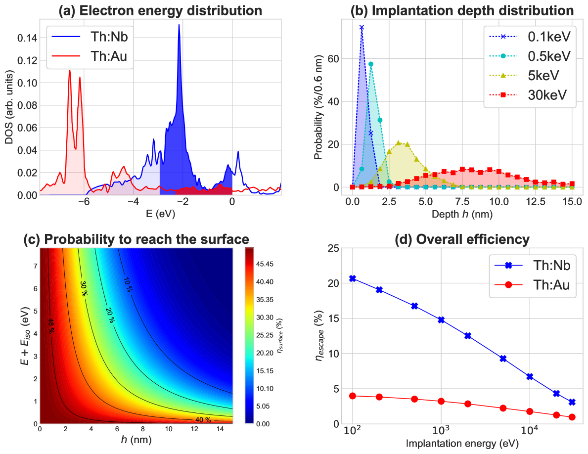
After excitation via internal conversion decay of the nucleus, a conversion electron travels from its initial position at depth h in the bulk material towards the surface and scatters elastically and inelastically. Inelastic scattering is characterized by the inelastic mean free path , which is a function of energy and can be approximated as universal for elementary metals Seah and Dench (1979). The starting position is defined by the implantation energy. 229Ac ions are implanted into the host at low energies of a few hundreds to a few thousands eV. At eV implantation energy the mean implantation depth is around nm for niobium with a lattice constant of nm Smirnov and Finkel (1966). Typical implantation profiles were obtained with the binary collision approximation using the SRIM software package and are shown in fig. 4 (b) Ziegler (2004). The probability of conversion electrons emitted isotropically at depth h with energy E, with respect to the Fermi level, to reach the surface is given by:
| (1) |
with equal to the polar angle. This probability is shown in fig. 4 (c) for elementary metals. At the surface the electrons have to overcome the surface potential characterized by the metal’s work function, E. Electrons stemming from electronic states close to the Fermi energy gain enough energy during internal conversion, while electrons from the lower part of the DOS distribution remain bound in the bulk material. Only electrons with an energy E + E can leave the bulk. The escape probability thus becomes:
| (2) |
Consequently, a high efficiency is obtained for host materials with a low work function and a high density of states in the region between -E+EWF and the Fermi level of the DOS, as shown by the dark shaded regions in fig. 4 (a). Electrons stemming from the lower energy region of the energy distribution (light shaded in the figure) remain bound and are not detected. Low-energy implantation deposits actinium ions close to the surface, such that electrons can reach the boundary without being scattered but deep enough that distortions by the surface are avoided.
DFT calculations were used to search for a host material with a DOS that maximizes the number of available electrons capable of reaching the surface. From these simulations, was computed as shown in table 2, after implantation at 100 eV energy. The choice of a suitable host material for the branching ratio experiment not only depends on the electronic structure, but also on the contamination of the material at the surface and in the bulk. The presence of contaminants in the bulk can change the electron kinetic energy distribution significantly, while an oxide layer at the surface additionally alters the work function. This oxide layer has to be thin enough, such that electrons can pass through it without experiencing losses and such that the workfunction is not significantly altered. A sample material with high purity should be chosen in order to be able to neglect their influence. Gold, as an inert element, is not exhibiting an oxide layer and is, additionally, available with high purity. However, at 100 eV implantation energy, its escape probability is limited to . Based on these efficiencies and as a trade-off between a favorable electronic structure, a low expected oxidation rate and the availability of pure sample material, niobium has been chosen as additional target material. The expected escape efficiencies at different implantation energies for gold and niobium are shown in fig. 4 (d).
| Th:X | (%) | Th:X | (%) |
|---|---|---|---|
| Th:Ag | 8 | Th:Nb | 21 |
| Th:Al | 9 | Th:Ni | 7 |
| Th:Au | 4 | Th:Pd | 6 |
| Th:Ba | 20 | Th:Pt | 3 |
| Th:Cu | 5 | Th:Ti | 18 |
| Th:Hf | 35 | Th:V | 20 |
| Th:Lu | 29 | Th:Zr | 23 |
| Th:Mo | 9 |
VII Crystal Characterisation
To detect the radiative decay of the Th isomer in the VUV spectroscopy experiment proposed in section III, it is essential to inhibit the IC decay channel. As mentioned above, this can be achieved by using large band gap crystals as a host for the 229Th isomer. Due to the band gap being larger than the isomer energy, there are no available electronic states for internal conversion and the crystal, without dopants or colour centers, is transparent to the emitted VUV photon (or incoming VUV photons) upon decay to the 229Th ground state. However, depending on the local atomic configuration (e.g. occupied lattice site and charge compensation mechanism) of the thorium impurities in the host crystal, states can be introduced inside the band gap energy region. If these gap states reduce the size of the band gap below the isomer energy, the IC decay channel is no longer suppressed and will dominate over the radiative channel. In addition, a hyperfine structure originating from a non-vanishing electric field gradient at the Th site causes a homogeneous shift in transition energy of the order of eV Kazakov et al. (2012). Since this shift also depends on the local configuration it is necessary for all thorium atoms to be in the same lattice location and configuration for a final VUV spectroscopy experiment aiming at a highest accuracy.
The concept to suppress the IC decay channel with a large band gap material is illustrated for CaF2, a well-studied material and a suited host crystal with a direct band gap of eV Rubloff (1972). Theoretical calculations predict a lowest-energy configuration of Th atoms in a CaF2 crystal, whereby the Th4+ ions occupy Ca2+ substitutional sites with a charge compensation mechanism of two neighboring F- interstitials Dessovic et al. (2014). Whereas this local configuration is not expected to reduce the band gap significantly, allowing for high-resolution spectroscopy, there is no experimental insight in the occupancy fraction of this configuration, depending on the production method of the Th ensemble. A low occupancy fraction could present a severe loss in signal during VUV spectroscopy. In the context of the spectroscopy approach proposed in this work, it is crucial to identify and quantify eventual non-substitutional 229Th incorporation resulting from the implantation of a 229Ac parent isotope (e.g. in interstitial or disordered sites). The emission channeling technique is particularly suitable for such studies Höfsass and Lindner (1991). After the implantation of a suitable radioactive isotope, the particles emitted upon decay (, or ) interact with the screened periodic Coulomb potential of the crystal lattice. The atomic rows and planes of the crystal determine an anisotropic scattering of the emitted particles, resulting in emission patterns that are very sensitive to the exact position of the radioactively decaying nucleus within the lattice. A sensitivity of Å can be reached for the position of the radioactive species Pereira et al. (2014). Since the substitutional thorium configuration is the lowest-energy configuration it might be possible to increase its default occupancy fraction by annealing. A position-sensitive detector measures the 2D electron emission patterns around selected crystal axes. Fitting these experimental data with linear combinations of patterns simulated for various possible lattice sites allows to quantitatively and unambiguously determine the lattice site occupancy. Lattice sites with an occupancy fraction down to % are detectable in this way.
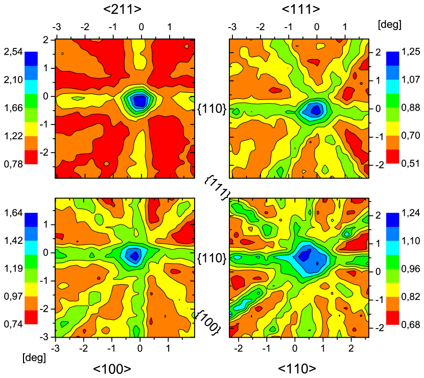
At ISOLDE, CERN, multiple actinium isotopes can be implanted into CaF2 to determine the lattice location of thorium dopants. The 229Th isotope can not be studied directly due to its very long half-life (T, emitter). Nevertheless, emission channeling experiments can be performed on implanted 229Ac (, emitter) to determine the lattice location of Th’s mother isotope. An implantation yield of pps is required in this case. The eV recoil energy transferred to the 229Th daughter nucleus upon decay is not sufficient for atomic displacement. Therefore, the 229Th atoms are expected to occupy the same lattice site as the implanted 229Ac atoms. A first series of emission channeling experiments with 229Ac has been performed in the online EC-SLI set-up at ISOLDE, CERN Silva et al. (2013). The measured 2D emission channeling patterns from 229Ac, implanted at room temperature, in the vicinity of the CaF2 , , and crystallographic directions are shown in fig. 5. The symmetry of these patterns corresponds to the crystal structure of CaF2. This indicates that the CaF2 crystal does not sustain severe damage under this heavy ion implantation which could hamper emission channeling experiments. Additionally, the data show that a large fraction of the 229Ac atoms occupy calcium substitutional positions. Further analysis of these patterns is ongoing.
Besides 229Ac, other isotopes can be used as substitute. Different isotopes of the same element are chemically identical. Hence, the local atomic configuration of thorium and actinium atoms in a crystal should not depend on the implanted isotope itself. In the future, it could be possible for the laser ion source at ISOLDE to also produce a 231Ac (T) beam with yields of pps. 231Ac is an exceptionally well-suited parent isotope for emission channeling experiments because it decays () to 231Th (T), which, unlike 229Th, also decays via . The significant difference in lifetime allows the study of the lattice incorporation of the 231Ac parent (online) and, afterwards, of the 231Th daughter (offline) Wahl et al. (2004). These two successive decays after the implantation of 231Ac is an ideal proxy for what occurs with the 229Ac/229Th decay in the VUV spectroscopy experiment proposed here, since the positions of both 231Ac and 231Th can be studied in the same experiment, separately.
VIII Summary
To allow for the development of the Th’s potential applications, two key observables remain unknown: its radiative lifetime and excitation energy. The way the isomer is produced has a distinct influence on the results, when attempting to determine these observables through the detection of the radiative Th-229Th transition. To this end, a concept to use 229Ac’s decay as an alternative production method of the Th isomer is presented. The photons of the Th-229Th transition will be identified and scrutinized through a high-resolution spectrometer after feeding of the isomer with the decay of implanted 229Ac ions in a large-bandgap host. Production of Th via 229Ac reveals a number of benefits over the commonly used decay of 233U. These advantages include the availability of an isotopically pure, intense source of 229Ac from the ISOLDE facility, an expected larger branching ratio towards Th, a more manageable decay half-life, a lower radioluminescence background for VUV spectrometery compared to other concepts and a controlled background characterization. Preparatory experiments, testing key ingredients of this concept, were conducted at ISOLDE. These experiments have confirmed, first, the availability of a high intensity, pure 229Ac ion beam. Next, in an attempt to determine the -decay branching ratio towards the isomer, no signal with its anticipated 7 s half-life was observed and further analysis should provide more insight. Finally, emission channeling patterns were obtained for 229Ac ions, implanted at 30 keV energy in a CaF2 crystal, indicating a significant calcium substitutional positioning in the CaF2 host.
Acknowledgements.
This work has received funding from Research Foundation Flanders (FWO, Belgium), by GOA/2015/010, C14/18/074 (BOF KU Leuven), from the European Union’s Horizon 2020 research and innovation programme under grant agreement No 654002 (ENSAR2) and No824096 (RADIATE), from the European Research Council under the ERC-2011-AdG-291561-HELIOS, from the Spanish MINECO via project FPA-2015-65035-P and from the FCT-Portugal, project CERN-FIS-PAR-0005-2017.References
- Kroger and Reich (1976) L. Kroger and C. Reich, Nuclear Physics A 259 (1976).
- Burke et al. (2008) D. G. Burke, P. E. Garrett, T. Qu, and R. A. Naumann, Nuclear Physics A 809, 129 (2008).
- Gulda et al. (2002) K. Gulda, W. Kurcewicz, A. J. Aas, M. J. G. Borge, D. G. Burke, B. Fogelberg, I. Grant, E. Hagebø, N. Kaffrell, J. Kvasil, G. Løvhøiden, H. Mach, A. Mackova, T. Martinez, G. Nyman, B. Rubio, J. Tain, O. Tengblad, T. Thorsteinsen, and I. collaboration, Nuclear Physics A 703, 45 (2002).
- Canty et al. (1977) M. Canty, R. Connor, D. Dohan, and B. Pople, Journal of Physics G: Nuclear Physics 3 (1977).
- Bemis et al. (1988) C. E. Bemis, F. K. Mcgowan, J. L. C. Ford, W. T. Milner, R. L. Robinson, P. H. Stelson, G. Leander, and C. Reich, Physica Scripta 38 (1988).
- Barci et al. (2003) V. Barci, G. Ardisson, G. Barci-Funel, B. Weiss, O. E. Samad, and R. Sheline, Physical Review C 68 (2003).
- Ruchowska et al. (2006) E. Ruchowska, W. A. Płóciennik, J. Zylicz, H. Mach, J. Kvasil, A. Algora, N. Amzal, T. Bäck, M. G. Borge, R. Boutami, P. A. Butler, J. Cederkäll, B. Cederwall, B. Fogelberg, L. M. Fraile, H. O. U. Fynbo, E. Hagebø, P. Hoff, H. Gausemel, A. Jungclaus, R. Kaczarowski, A. Kerek, W. Kurcewicz, K. Lagergren, E. Nacher, B. Rubio, A. Syntfeld, O. Tengblad, A. A. Wasilewski, and L. Weissman, Physical Review C - Nuclear Physics 73, 1 (2006).
- Reich and Helmer (1990) C. W. Reich and R. G. Helmer, Physical Review Letters 64, 271 (1990).
- Helmer and Reich (1994) R. Helmer and C. Reich, Physical Review C 49, 1845 (1994).
- Irwin and Kim (1997) G. Irwin and K. Kim, Physical Review Letters 79, 990 (1997).
- Beck et al. (2007) B. R. Beck, J. A. Becker, P. Beiersdorfer, G. V. Brown, K. J. Moody, J. B. Wilhelmy, F. S. Porter, C. A. Kilbourne, and R. L. Kelley, Physical Review Letters 98, 1 (2007).
- Beck et al. (2009) B. R. Beck, C. Y. Wu, P. Beiersdorfer, G. V. Brown, J. A. Becker, K. J. Moody, J. B. Wilhelmy, F. S. Porter, C. Kilbourne, and R. L. Kelley, 12th International Conference on Nuclear Reaction Mechanisms (2009).
- Wense et al. (2016) L. V. D. Wense, B. Seiferle, M. Laatiaoui, J. B. Neumayr, H.-J. Maier, H.-F. Wirth, C. Mokry, J. Runke, K. Eberhardt, C. E. Düllmann, N. G. Trautmann, and P. G. Thirolf, Nature 533 (2016).
- Thielking et al. (2018) J. Thielking, M. Okhapkin, P. Glowacki, D. M. Meier, L. V. D. Wense, B. Seiferle, P. G. Thirolf, E. Peik, and C. E. Düllmann, Nature 556 (2018).
- Peik and Tamm (2003) E. Peik and C. Tamm, Europhysics Letters 61, 181 (2003).
- Peik and Okhapkin (2015) E. Peik and M. Okhapkin, Comptes Rendus Physique 16, 516 (2015).
- Campbell et al. (2012) C. J. Campbell, A. G. Radnaev, A. Kuzmich, V. A. Dzuba, V. V. Flambaum, and A. Derevianko, Physical Review Letters 108, 1 (2012).
- Berengut et al. (2009) J. C. Berengut, V. A. Dzuba, V. V. Flambaum, and S. G. Porsev, Physical Review Letters 102, 1 (2009).
- Tkalya (2011) E. V. Tkalya, Physical Review Letters 106, 1 (2011).
- Tkalya et al. (2015) E. V. Tkalya, C. Schneider, J. Jeet, and E. R. Hudson, Physical Review C 92 (2015).
- Zhao et al. (2012) X. Zhao, Y. N. Martinez de Escobar, R. Rundberg, E. M. Bond, A. Moody, and D. J. Vieira, Physical Review Letters 109, 4 (2012).
- Stellmer et al. (2016) S. Stellmer, M. Schreitl, G. A. Kazakov, J. H. Sterba, and T. Schumm, Physical Review C 94, 1 (2016).
- Seiferle et al. (2017) B. Seiferle, L. V. D. Wense, and P. G. Thirolf, Physical Review Letters 118, 1 (2017).
- Wense et al. (2018) L. Wense, B. Seiferle, and P. G. Thirolf, Measurement Techniques 60, 1178 (2018).
- Ferrer et al. (2017) R. Ferrer, A. Barzakh, B. Bastin, R. Beerwerth, M. Block, P. Creemers, H. Grawe, R. de Groote, P. Delahaye, X. Fléchard, S. Franchoo, S. Fritzsche, L. P. Gaffney, L. Ghys, W. Gins, C. Granados, R. Heinke, L. Hijazi, M. Huyse, T. Kron, Y. Kudryavtsev, M. Laatiaoui, N. Lecesne, M. Loiselet, F. Lutton, I. D. Moore, Y. Martínez, E. Mogilevskiy, P. Naubereit, J. Piot, S. Raeder, S. Rothe, H. Savajols, S. Sels, V. Sonnenschein, J. C. Thomas, E. Traykov, C. Van Beveren, P. Van den Bergh, P. Van Duppen, K. Wendt, and A. Zadvornaya, Nature Communications 8, 14520 (2017).
- (26) NNDC, National Nuclear Data Center, www.nndc.bnl.gov .
- Pereira et al. (2011) L. M. C. Pereira, U. Wahl, S. Decoster, J. G. Correia, M. R. da Silva, A. Vantomme, and J. P. Araújo, Applied Physics Letters 98, 201905 (2011).
- Kofoed-Hansen (1948) O. Kofoed-Hansen, Physical Review 74, 3 (1948).
- Campbell et al. (2011) C. J. Campbell, A. G. Radnaev, and A. Kuzmich, Physical Review Letters 106, 1 (2011).
- Minkov and Pálffy (2017) N. Minkov and A. Pálffy, Physical Review Letters 118, 1 (2017).
- Hehlen et al. (2013) M. P. Hehlen, R. R. Greco, W. G. Rellergert, S. T. Sullivan, D. Demille, R. A. Jackson, E. R. Hudson, and J. R. Torgerson, Journal of Luminescence 133, 91 (2013).
- Van der Heyden et al. (1987) M. Van der Heyden, H. Micklitz, S. Bukshpan, and G. Langouche, Physical Review B 36 (1987).
- Dessovic et al. (2014) P. Dessovic, P. Mohn, R. Jackson, G. Winkler, M. Schreitl, G. Kazakov, and T. Schumm, Journal of Physics: Condensed Matter 26 (2014).
- Stellmer et al. (2015) S. Stellmer, M. Schreitl, and T. Schumm, Scientific Reports 5, 1 (2015).
- Borge and Jonson (2017) M. J. G. Borge and B. Jonson, Journal of Physics G: Nuclear and Particle Physics 44 (2017).
- Fedosseev et al. (2017) V. Fedosseev, K. Chrysalidis, T. D. Goodacre, B. Marsh, S. Rothe, C. Seiffert, and K. Wendt, Journal of Physics G: Nuclear and Particle Physics 44 (2017).
- Raeder et al. (2013) S. Raeder, M. Dombsky, H. Heggen, J. Lassen, T. Quenzel, M. Sjödin, A. Teigelhöfer, and K. Wendt, Hyperfine Interactions 216, 33 (2013).
- Armbruster et al. (2004) P. Armbruster, J. Benlliure, M. Bernas, A. Boudard, E. Casarejos, S. Czajkowski, T. Enqvist, S. Leray, P. Napolitani, J. Pereira, F. Rejmund, M.-V. Ricciardi, K.-H. Schmidt, C. Stéphan, J. Taieb, L. Tassan-Got, and C. Volant, Physical Review Letters 93, 212701 (2004).
- Dahl (2000) D. A. Dahl, International Journal of Mass Spectrometry 200, 3 (2000).
- Lejaeghere et al. (2016) K. Lejaeghere, G. Bihlmayer, T. Björkman, P. Blaha, Blügel, V. Blumm, I. Caliste, I. Castelli, S. Clark, A. Dal Corso, S. de Gironcoli, T. Deutsch, J. K. Dewhurst, I. De Marco, C. Draxl, M. Dułak, O. Eriksson, J. Flores-Livas, K. Garrity, L. Genovese, P. Giannozzi, M. Giantomassi, S. Goedecker, X. Gonze, O. Grånäs, E. Gross, A. Gulans, F. Gygi, D. Hamann, P. Hasnip, N. Halzwarth, D. Iuçan, D. Jochym, F. Jollet, D. Jones, G. Kresse, K. Koepernik, E. Küçükbenli, Y. Kvashnin, I. Locht, S. Lubeck, M. Marsman, N. Marzari, U. Nitzsche, L. Nordström, T. Ozaki, L. Paulatto, C. Pickard, W. Poelmans, M. Probert, K. Refson, M. Richter, G.-M. Rignanese, S. Saha, M. Scheffler, M. Schlipf, K. Schwartz, S. Sharma, F. Tavazza, P. Thunström, A. Tkatchenko, M. Torrent, D. Vanderbilt, M. van Setten, V. Van Speybroeck, J. Wills, J. Yates, G.-X. Zhang, and S. Cottenier, Science 351 (2016).
- Cottenier (2013) S. Cottenier, Density Functional Theory and the family of (L)APW-methods: a step-by-step introduction, 2nd edition, appendix B, ISBN 978-90-807215-1-7, freely available at http://www.wien2k.at/reg user/textbooks (2002-2013).
- Seah and Dench (1979) M. Seah and W. Dench, Surface And Interface Analysis 1, 2 (1979).
- Smirnov and Finkel (1966) Y. M. Smirnov and V. A. Finkel, Soviet Physics JETP 22, 750 (1966).
- Ziegler (2004) J. F. Ziegler, Nuclear Instruments and Methods in Physics Research, Section B: Beam Interactions with Materials and Atoms 219-220, 1027 (2004).
- Kazakov et al. (2012) G. Kazakov, A. Litvinov, V. Romanenko, L. Yatsenko, A. Romanenko, M. Schreitl, G. Winkler, and T. Schumm, New Journal of Physics 14 (2012).
- Rubloff (1972) G. W. Rubloff, Physical Review B 5 (1972).
- Höfsass and Lindner (1991) H. Höfsass and G. Lindner, Physics Reports 201 (1991).
- Pereira et al. (2014) L. M. C. Pereira, U. Wahl, J. G. Correia, L. M. Amorim, D. J. Silva, S. Decoster, M. R. Silva, K. Temst, and A. Vantomme, Nuclear Inst. and Methods in Physics Research, B 332, 143 (2014).
- Silva et al. (2013) M. R. Silva, U. Wahl, J. G. Correia, L. M. Amorim, and L. M. C. Pereira, Review of Scientific Instruments 84 (2013).
- Wahl et al. (2004) U. Wahl, J. G. Correia, A. Czermak, S. G. Jahn, P. Jalocha, J. Marques, A. Rudge, F. Schopper, J. Soares, A. Vantomme, P. Weilhammer, and the ISOLDE collaboration, Nuclear Inst. and Methods in Physics Research, A 524, 245 (2004).