Magnonic Analogue Black/White Hole Horizon in Superfluid 3He-B: experiment
Abstract
We provide experimental details of the first experiment made in zero temperature limit ( 600 K) studying the magnonic black/white hole horizon analogue using absolutely pure physical system based on the spin superfluidity in superfluid 3He-B. We show that spin precession waves propagating on the background of the spin super-currents in a channel between two Bose-Einstein condensates of magnons in form of homogeneously precessing domains mimic the properties of the black/white horizon. Once the white hole horizon is formed and blocks the propagation of the spin-precession waves between two domains, we observed an amplification effect, i.e. when the energy of the spin precession waves reflected from the horizon is higher than the energy of the excited spin precession waves before horizon was formed. Moreover, the estimated temperature of the spontaneous Hawking radiation in this model system is about four orders of magnitude lower than the system’s background temperature what makes it a promising tool to study the effect of spontaneous Hawking radiation.
pacs:
04.70.-s, 67.30.-n, 67.30.H-, 67.30.hj, 67.30.erI INTRODUCTION
One of the most exciting outcomes of the quantum field theory in curved space-time is the Hawking‘s famous prediction that the gravitational black holes are not stable objects, they are spontaneously evaporating by radiating particles due to quantum fluctuations on the event horizon hawking . As this radiation has a thermal spectrum, the black holes have non-zero temperature (so-called the Hawking temperature), the magnitude of which is inversely proportional to the black hole mass. However, a smallness of the Hawking temperature (for solar mass black hole 60 nK) in comparison with the temperature of the cosmic microwave background radiation ( 3 K) makes the direct experimental measurement of the Hawking temperature using current technologies impossible. Solving conceptual issues with theoretical treatment of the Hawking radiation - so-called trans-Planckian problem, W. Unruh showed that the behaviors of classical and quantum fields in curved space-times are more-less analogical, and suggested to test the validity of Hawking’s prediction using experimentally created black-hole-horizon. In particular, by measuring a thermal spectrum of sound waves emitted from the sonic horizon in transonic fluid flow unruh1 ; visser . This suggestion has triggered and motivated as theoretical so experimental search for physical systems which could serve as a model tool mimicking the properties of the black-hole horizon.
The physical principle of an experimental black/white hole (or event horizon) formation is based on the controlled transition between subcritical and supercritical (and vice-versa) regimes of the propagation of a particular perturbation on the background of the flow allowing to distribute the perturbation over physical system. A black-hole horizon for perturbation in a flowing medium is formed by a transition from subluminal to superluminal flow, such that perturbation spreading along the flow and passing from the subluminal to superluminal region cannot return back to the subluminal region. On the other hand, a white-hole horizon is a region where the flow changes from superluminal to subluminal. In this case, a perturbation traveling against the flow from the subluminal region cannot penetrate the superluminal part.
Except above mentioned sound waves in trans-sonic fluid flow, the portfolio of such systems were extended by: atomic Bose-Einstein condensate garay , light in dispersive media light , the surface waves on flowing fluid ralf ; rousseaux1 ; rousseaux2 ; silke , hydraulic jumps in flowing liquids volovik ; jannes , light in optical fibre philbin and ultra-cold fermions BEC2 . Therefore, in light of this, the Hawking radiation can be viewed as universal phenomenon of a dynamic nature in the various physical systems having capability, at certain conditions, to form a boundary - an event horizon, and the fundamental dynamical property of any event horizon analogue is a spontaneous emission of thermal Hawking radiation, the temperature of which depends on the magnitude of the velocity gradient on the horizon unruh1 ; ralf1
| (1) |
It turns out however, that this temperature is typically a several orders of magnitude lower than the background temperature of the physical systems used as experimental tool modeling properties of the black/white hole horizon. Solution to this problem seems to be to find a physical system, the background temperature of which would approaching the absolute zero temperature, and simultaneously would have the properties allowing to model the black/white horizon garay ; BEC2 ; BEC3 ; magnonic .
In this article we provide all experimental details and discuss the results of the first experiment made in zero temperature limit ( 600 K) studying the magnonic black/white hole horizon analogue using absolutely pure physical system based on the spin superfluidity in superfluid 3He-B spinhole . Main experimental results were published in prl2019 .
II IDEA OF EXPERIMENT
First let us explain the concept of the experiment. The schematic 3-D cross section of the experimental chamber and concept of the experiment is shown in Fig. 1. The experimental chamber with superfluid 3He-B consists of two cylindrical cells mutually connected by a channel. The chamber is placed in steady magnetic field and magnetic field gradient B, both oriented along -axis.

Using cw-NMR technique, we created a Bose-Einstein condensate of magnons in a form of the homogeneously precessing domain (HPD) in both cylindrical cells. The HPD is a dynamic spins structure formed in a part of the cell placed in lower magnetic field which, with an aid of the dipole-dipole interaction, coherently precess around a steady magnetic field at the angular frequency hpd1 ; fomin . Within the rest of cell, the spins are co-directional with the steady magnetic field and do not precess. These two regions (domains) are separated by a planar domain wall, the position of which is determined by the Larmor resonance condition , where is the gyromagnetic ratio of the 3He nuclei.
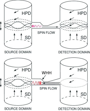
To model black/white hole horizon in superfluid 3He-B, we used two fundamental physical properties of the HPD: the spin (magnonic) superfluidity and the presence of the HPD’s collective oscillation modes in a form of the spin precession waves (see below). The spin superfluidity allows to create and manipulate the spin flow, i.e. the spin super-currents flowing between precessing domains as a consequence of the phase difference between the phases of spin precession in individual domains moscow . The spin precession waves serve as a probe testing formation and presence of a black/white hole horizon inside the channel: channel has restriction allowing to reach the different regimes of the velocity of the spin super-current flow with respect to the group velocity of the travelling spin-precession waves. The spin super-currents affect the transfer of the spin precession waves i.e. axial oscillation modes of the domain wall excited by longitudinal coil in one of the HPD (source domain) and detected in the second, receiving HPD (detection domain) as a function of the phase difference in the spin precession of HPDs, i.e. as a function of the spin flow velocity. This is similar to the experiment suggested by R. Schützhold and W. Unruh ralf and later performed by G. Rousseaux et al. rousseaux1 ; rousseaux2 and by S. Weinfurtner et al. silke . In the presented experiment, the magnetic field gradient B plays the role of gravitational acceleration, the spin super-currents represent the water flow, and the spin-precession waves correspond to the gravity waves on the water’s surface.
III EXPERIMENT
As mentioned above, the experiment was performed in the experimental cell, the 3-D cross-section of which is shown in Fig. 1. The inner diameters of both cylinders were 6 mm and heights were 7 mm. The channel connecting two cylinders was 13 mm long and in order to create a spatial gradient in spin flow velocity , the channel had an asymmetric reduction in its center. The length of sharpest restriction was 0.5 mm and after restriction the channel dimensions were reduced. The reduced channel was 2 mm long and its cross-section had dimension of 0.4 3 mm2 (see Fig. 1). The experimental cell was mounted on a diffusion-welded copper nuclear stage and cooled down stage . The cell was filled with 3He at temperature of 1 K, and then pressurized to 3 bars. Subsequent demagnetizations of the copper nuclear stage allowed to cool 3He into superfluid state, down to temperature 0.5 Tc, at which the measurements were performed. Temperature of 3He was measured by means of a powdered Pt-NMR thermometer placed in bottom part of thermometric volume (Pt-NMR thermometer is not shown in Fig. 1). Temperature was calibrated against Tc - the transition temperature of 3He into superfluid state.
Two HPDs were simultaneously and independently generated in both towers using two programmable function rf-generators working in the phase-locked mode at angular frequency rad/sec and with zero phase difference adjusted between excitation voltage signals. The induced NMR signals were amplified by pre-amplifiers and measured by two rf-lock-in amplifiers, each controlled by its own generator. As the position of the domain walls in both towers follows the plane, where the Larmor resonance condition is satisfied, i.e. , the position of both domain walls (i.e. also the size of the HPDs) can easily be controlled and adjusted by steady magnetic field (a current source supplying the NMR magnet).
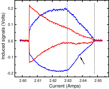
Figure 2 shows the absorption (in red) and dispersion (in blue) NMR signals from two simultaneously generated HPDs as a function of the current supplying the NMR magnet. While absorption signals are proportional to the energy dissipation, the amplitude of the dispersion signals correspond to the HPD volume. There are three relaxation processes leading to the power dissipation in the HPD. A total HPD power dissipation in a cylindrical experimental cell of radius with -axis of the cell orientated along the magnetic field and its gradient can be expressed as jltp1997
| (2) |
The first term describes the relaxation of the two-domain structure by the spin diffusion across the domain wall of cross-section with being the transverse component of the spin-diffusion tensor for gradients along the -direction. Here is the domain wall thickness, is the domain wall shape-dependent constant of the order of unity and is the temperature dependent susceptibility of the BW state with Fermi-liquid corrections. The second term represents a relaxation process caused by the distortion of the bulk order parameter near the walls of the experimental cell, where is the constant characterizing the surface relaxation rate surf . The third term refers to the relaxation through the intrinsic Leggett-Takagi mechanism with being the effective Leggett-Takagi relaxation time, where and is the HPD length in cylindrical cell lt .
In Fig. 2 the dot-dashed lines mark the beginning and the end of the experimental cell. While sweeping magnetic field down, both HPDs begin to be formed on the top of the cell, when the Larmor resonance condition is satisfied there. On the further reduction of the magnetic field, the Larmor resonance condition moves along - axis of the cell, and so do the domain walls of both HPDs. The dispersion signals increase linearly as the volume of the each HPD grows in cylindrical cell. Penetration of the domain walls into the channel is associated with the change in slopes of measured signals, mainly dispersion ones. Asymmetry in absorption signals from HPDs is caused by a spin current flowing between the HPD due to a non-zero phase shift between rf-excitation fields used for HPDs generation. In fact, what determines the magnitude of the spin flow between domains is the phase difference between rf-fields (i.e. the electric currents) generated by the excitation coils and not the phase difference in excitation voltage signals provided by rf-generators. As the resonance circuits are not perfectly matched, there is a few degrees phase shift between rf-fields, no matter that a zero phase difference between voltage excitation signals from locked generators was adjusted. Resulting spin flow transfers the energy between domains that leads to asymmetry in measured signals. When both HPDs fulfil entire cell, the dispersion signals saturate. Further field reduction causes the increase of the energy dissipation due to the Leggett-Takagi relaxation mechanism, until the rf-fields (with aid of the spin super-currents) can not cover the energy losses and both HPDs “decease”. It is worth to note that when the domain wall is placed inside the cell (the case of this experiment), the dominant process of the energy dissipation is the spin diffusion.
Once two HPDs were generated, the position of the domain wall has to be adjusted into channel. Although, the penetration of the domain walls into channel manifests itself as a change in the slope of the dispersion signals (see Fig. 2), we used another method based on generation of the collective oscillations modes of the HPD-SD structure (see below), and application of this method allowed us to adjust the domain wall position in the channel with resolution of a few tens of m (depending on the value of the magnetic field gradient).
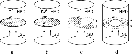
Figure 3 shows a schematic visualization of the various kinds of collective oscillations mode - spin precession waves of the HPD-SD spin structure, i.e. the various forms of the small oscillations of the phase of the spin precession in the HPD. The physics and the measurements methods of these modes are very well understood and developed, respectively Fomin87 ; torsional ; moscow1 ; vovka ; euro ; waves ; prl2008 ; matoprb2012 . The dispersion relation for the spin-precession waves travelling along the HPD-SD interface placed far from horizontal wall of the cell was derived in form matoprb2012
| (3) |
where is the transverse wave vector, is the cell radius, , are zeroes of the derivative of the Bessel function, and denote the spin wave velocities with respect to the longitudinal or transversal direction to the magnetic field direction, respectively, and .
In presented experiment we used the first axial surface mode as a probe testing the formation of the event horizon in channel. The procedure is as follows: as the first step, for given value of the magnetic field gradient, the domain wall was set at the position above the channel using steady magnetic field , that is at the position before the change in the slope of the dispersion signals occur. Then we added small harmonically oscillating longitudinal magnetic field generated by one coil, and using the frequency sweep of this longitudinal field we found the first axial oscillation mode of the domain wall.
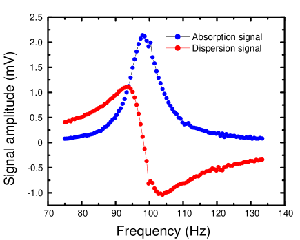
Figure 4 shows the resonance characteristics of a spin precession wave (the first axial mode) excited by the longitudinal coil in one HPD, when the domain walls are placed above the channel at the constant field gradient . Then, by sweeping the position of domain wall (i.e. sweeping the magnetic field ) along the experimental cell and simultaneously continuously exciting the longitudinal coil on the resonant frequency of the spin wave, the position of the domain wall in channel can be determined from the amplitude of measured resonance signal.
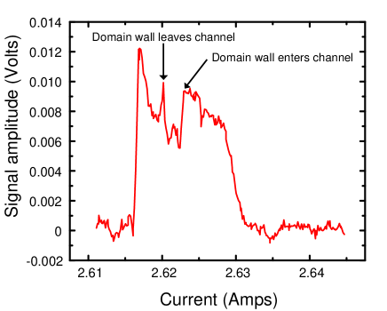
Figure 5 presents such dependence of the amplitude of the spin wave resonance signal as a function of the domain wall position, i.e. the value of the current supplying NMR magnet. There is obvious abrupt decrease of the signal, when the domain wall penetrates into channel being followed by sudden signal increase, when the domain wall leaves the channel. Latter change serves as a reference level to adjust the position of the domain wall in the channel, as the channel base is flat. In fact, reaching the value of the current (field ), at which the domain wall left the channel, we reversed the current and returned the domain wall back to the channel by adding 4-5 steps of the current source. The precision of the domain wall adjustment in channel is given by , where T is the field step controlled by the current source source , and for =15 mT/m giving a spatial precision of 50 m. The estimated length of the precessing layer in the channel is 150 m 50 m. For comparison, the domain wall thickness for the above mentioned experimental conditions is 0.34 mm.
The flow of the spin super-currents between precessing domains can be created by the phase gradient of the spin precession Fomin87
| (4) |
where is the spin deflection angle. The spin flow between precessing domains can be established in both directions depending on the sign of the phase difference , while the spin flow velocity depends on the magnitude of as
| (5) |
The group velocity of the propagating spin precession waves is expressed as
| (6) |
Here and denote already mentioned the longitudinal and transverse spin wave velocities with respect to the magnetic field orientation, respectively, and is the HPD length in the channel. We shall assume that is localized on the length of the sharpest restriction in the channel of the order = 0.5 mm, therefore .
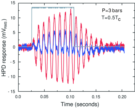
After setting the position of the domain wall in the channel and adjusting the phase difference i.e. adjusting the amplitude and direction of the spin flow velocity , we excited the spin-precession waves. The spin-precession waves in the source domain were generated by applying 8 sinusoidal pulses at their resonance frequency using separate generator. The low frequency signals representing spin precession waves from the both, the source and detection HPDs for a particular value of were extracted using demodulation technique i.e. by means of rf-detector and a low-frequency filter. These low frequency signals were subsequently captured and stored by a digital oscilloscope for the data analysis. Figure 6 shows examples of the time evolution of the corresponding signals of the excited spin-precession waves in the source domain and incoming waves in the second, detection domain. The excitation pulse builds-up the spin precession waves. When the pulse is over, the spin precession waves decay due to dissipation mechanisms. We analysed just these free decay signals by the methods of the spectral analysis as a function of the phase difference .
IV Results and Discussion
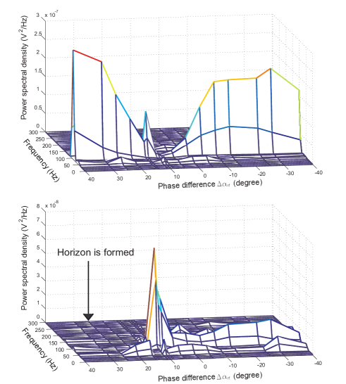
Figure 7 shows the power spectral density (PSD) of the free decay signals measured in the source (upper) and in the detection (lower) domains as a function of the phase difference i.e. as a function of the direction and the amplitude of the spin flow velocity. As one can see, there are a few remarkable characteristics to be seen in these dependencies. Firstly, the upper figure shows the strong PSD signals being detected in the source domain with an exception of a deep minimum in region of corresponding to 10∘. Secondly, the lower figure shows the weaker PSD signals of the incoming spin precession waves detected in the detection domain in the range of negative values of up to 10∘, above which a peak signal was detected. Thirdly, no PSD signals (within experimental resolution) were measured in the detection domain for values of 20∘. We interpret observed dependencies as follows. A schematic illustration of the spin precession waves dynamics in the channel are presented in Fig. 8.
The negative values of the phase difference cause the spin super-current to flow from the source domain towards the detection one (see Fig. 8). Thus, the spin-precession waves excited in the source domain are dragged by these spin-currents and travel downstream to the detection domain, where they are detected (see Fig.7 bottom). The frequency of excited spin-precession waves corresponds to that of the fundamental axial mode of an isolated domain (see Fig. 4). However, the out-flowing or in-flowing spin super-current varies the conditions on the boundary of a domain wall and thus modifies the frequency of its fundamental mode. Therefore, the frequency of incoming spin-precession wave slightly differs from the resonance frequency of the standing wave, and consequently, the amplitude of detected oscillations is lower (reduction in the wave amplitude is also caused by the dissipation).
Presence of the deep signal minimum in the source domain and corresponding signal maximum in the detection domain for 10∘ - 15∘ we interpret as a consequence of zero spin super-current between domains which leads to a resonance match between cavities. We remind that what determines the phase of the spin precession in HPDs is the phase of the rf-field i.e. the phase of the electrical current flowing the resonance circuit and not the phase of the excitation voltage provided by the generator (which we used as adjustable parameter). A small mismatch between the real resonance frequency and the frequency of the voltage excitation leads to a small phase shift between the excitation voltage and electrical current. This explains why zero spin super-current flows between the domains at the phase difference 10∘ - 15∘. Now, from point of view of the axial oscillations, two HPDs represent two resonance cavities connected by means of the channel. As the spin super-current absences between HPD’s, and the spin super-currents modify the boundary conditions for the axial mode, this sets the condition for the resonance match between these cavities. Due to this, the whole energy of the spin-precession waves excited in the source domain is almost immediately transferred to and absorbed by the detection domain at once. This is detected as a missing signal in the source domain, where the waves were excited (!), while the detection domain shows a maximal PSD signal (see Fig. 7).
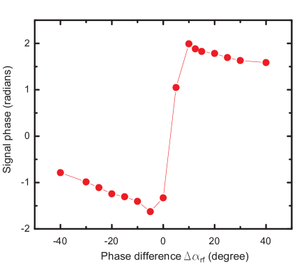
For phase difference 10∘ the flow direction of the spin super-currents is reversed, i.e. the spin super-currents flow from the detection domain towards the source domain and emitted the spin-precession waves propagate against this flow. The change in the flow direction of the spin super-currents is also seen on the phase of the decay signals from the source domain as a gradual phase shift by 180∘ (see Fig. 9 ). This is because the frequency of the spin precession waves crosses from the values slightly lower to the values slightly higher (or vice versa) than the resonance frequency of the spin-precession waves of the isolated HPD.
As one can see from Fig. 7, there are no signals detected in the detection domain for 20∘. We interpret this as a formation of the magnonic white hole horizon in the channel: the spin-precession waves sent from the source domain towards to the detection domain are blocked in the channel by the flow of spin super-currents, and never reach the detection domain (see Fig. 8). This interpretation is supported by the calculation using above presented theoretical model: the white hole horizon is formed in a place, where and when the condition is satisfied (see Eqs. (5) and (6)).
Figure 10 shows a dependencies of the HPD length in the channel on the phase difference that satisfy the “event horizon” condition assuming that is localized and concentrated on the sharpest restriction in the channel i.e. on the length of . Dependencies were calculated for three different values of as stated in the caption of Fig. 10. Taking the value of the phase difference , at which a white horizon in the channel is formed, i.e. 25∘ (see Fig. 7), one can find that to satisfy theoretically predicted condition for horizon formation, the corresponding length of the HPD in the channel should be of the order of 100 m, depending on the length of restriction. This value is in reasonable agreement with that determined from experiment = 150 m 50 m.
Simultaneous measurement of both free decay signals of the spin precession waves from the source and the detection domains allows a cross-correlation function between these two signals to be determined. Figure 11 shows the cross power spectral density between these two signals as a function of the phase difference i.e. as a function of the spin flow velocity . As mentioned above, for values of 0∘, i.e. when the spin super-currents drag the excited spin precession waves from the source domain towards to the detection domain, the decay signals from both domains are correlated. For values of 0∘, reduction and subsequent reversion of the spin super-currents affects the dynamics of the propagation of the spin precession waves that leads to the change in the correlation between the decay signals detected in both domains. When the spin super-currents approaches zero value, due to resonance match between domains, the energy is transferred in both directions that is manifested as correlation/anti-correlation peaks. However, when the white horizon is formed (25∘), the decay signals are anti-correlated. We may interpret this in a way that the rise of the decay signal in source domain is paid by the spin flow flowing from detection domain towards to the source domain - in agreement with theoretically predicted amplification of the wave on the horizon paid by the energy of the flow unruh2 . This interpretation is supported by the dependence presented in Fig. 7 (upper dependence), where a notable feature regarding to the absolute values is showed: when the spin super-current flows from the detection domain to the source domain, the spin precession waves in the source domain have a tendency to have a higher power spectral density amplitude than those when the spin super-current flowing in opposite direction. However, to elucidate the physical origin of the observed phenomena additional experiments have to be done.
Finally, to check the formation of the magnonic white hole horizon in channel we performed measurements adjusting the phase difference between HPDs rf-excitation voltages to be + 25∘, but instead using the pulse technique to excite the spin precession waves we used the continuous excitations. That is, we used a full frequency sweep and simultaneously measured signals from both domains. Figure 12 shows absorption and dispersion signals from the source and detection domains. The presence of the spin precession waves excited in the source domain is manifested by strong signals. However, there are no signals detected in the detection domain: as the spin precession waves excited in the source domain are propagating against the spin super-current, they reach a horizon and they are reflected back never penetrating into the detection domain.
V CONCLUSION
In conclusion, we provided experimental details of an experiment in a limit of absolute zero temperature probing the magnonic black/white hole horizon analogue in superfluid 3He-B. As an experimental tool simulating the properties of the black/white horizon we used the spin precession waves propagating on the background of the spin super-currents between two Bose-Einstein condensates of magnons in form of homogeneously precessing domains. We showed that by adjusting the external parameters of experiment, we can form a white hole horizon inside the channel, and this horizon blocks the propagation of the spin-precession waves between two domains. Once the white hole horizon was formed, we observed an amplification effect, when the energy of the reflected spin precession waves from the horizon is higher than the energy of the spin precession waves excited before the horizon was formed. Even more, the presented results manifest that the spin-precession waves propagating on the background of the spin super-currents between two HPDs possess all physical features needed to elucidate physics associated with the presence of the event horizons, e.g. to test the spontaneous Hawking process. In fact, assuming that the spin super-currents velocity of the order of 1 m/s varies on the length of m one can estimate the temperature of the Hawking radiation in this system to be of the order of 10 nK, what is a temperature only four orders of magnitude lower that the background temperature, and this makes presented system a promising tool to investigate this radiation.
VI ACKNOWLEDGEMENT
We acknowledge support from the European Microkelvin Platform (H2020 project 824109), APVV-14-0605, VEGA-0128, CEX-Extrem SF of EU (ITMS 26220120047). We wish to acknowledge the technical support provided by Š. Bicák and G. Pristáš. Financial support provided by the US Steel Košice s.r.o. is also very appreciated
References
- (1) S. W. Hawking, Nature 248, 30 (1974).
- (2) W. G. Unruh, Phys. Rev. Lett. 46, 1351 (1981).
- (3) M. Visser, Class. Quantum Grav. 15,1767 (1998).
- (4) S. J. Robertson, J. Phys B: At. Mol. Opt. Phys. 45, 163001 (2012).
- (5) R. Schützhold and W. G. Unruh, Phys. Rev. D 78, 041504(R) (2008).
- (6) L. J. Garay, J. R. Anglin, J. I. Cirac, and P. Zoller, Phys. Rev. Lett. 85, 4643 (2000).
- (7) U. Leonhardt and P. Piwnicki, Phys. Rev. Lett. 84, 822 (2000).
- (8) R. Schützhold and W. G. Unruh, Phys. Rev. D 66, 044019 (2002).
- (9) G. Rousseaux, Ch. Mathis, P. Maïssa, T. Philbin, and U. Leonardt, New J. Phys. 10, 053015 (2008).
- (10) G. Rousseaux, P. Maïssa, Ch. Mathis, P. Coullet, T. G. Philbin, and U. Leonardt, New J. Phys. 12, 095018 (2010).
- (11) S. Weinfurtner, E. W. Tedford, M. C. J. Penrice, W. G. Unruh and G. A. Lawrence, Phys. Rev. Lett. 106, 021302 (2011).
- (12) G. E. Volovik, JETP Lett. 82, 624 (2005).
- (13) G. Jannes, R. Piquet, P. Maissa, C. Mathis, G. Rousseaux, Phys. Rev. E 83, 056312 (2011).
- (14) T. G. Philbin, Ch. Kuklewicz, S. Robertson, S. Hill, F. Konig and U. Leonhardt, Science 319, 1367 (2008).
- (15) S. Giovanazzi, Phys. Rev. Lett. 94, 061302 (2005).
- (16) O. Lahav, A. Itah, A. Blumkin, C. Gordon, S. Rinott, A. Zayats, J. Steinhauer, Phys. Rev. Lett. 105, 240401 (2010).
- (17) A. Roldán-Molina, A. S. Nunez, and R. A. Duine, Phys. Rev. Lett. 118, 061301 (2017).
- (18) P. Skyba, Superfluid He-3 as a model system for cosmology - Experimental point of view. Lecture Notes in Physics 718 Ed. W. G. Unruh and R. Schützhold, DOI 10.1007/3-540-70859-6-5, Springer Verlag (2007).
- (19) M. Človečko, E. Gažo, M. Kupka, P. Skyba, submitted to PRL.
- (20) A. S. Borovik-Romanov, Yu. M. Bunkov, V.V. Dmitriev, Yu. M. Mucharskii, JETP Lett. 40, 1033 (1984).
- (21) I. A. Fomin, JETP Lett. 40, 1037 (1984).
- (22) A. S. Borovik-Romanov, Yu. M. Bunkov, A. De Waard, V. V. Dmitriev, V. Makróczyová, Yu. M. Mukharskii, D. A Sergackov, JETP Lett. 47, 478 (1988).
- (23) P. Skyba, J. Nyéki, E. Gažo, V. Makróczyová, Yu. M. Bunkov, D. A. Sergackov, A. Feher, Cryogenics 37, 293 (1997).
- (24) A. Feher, R. Harakály, L. Lokner, E. Gažo, M. Kupka, J. Nyéki, P. Skyba, Yu. M. Bunkov, O. D. Timofeevskaya, J. Low Temp. Phys.108, 461 (1997).
- (25) T. Ohmi, M. Tsubota, T. Tsuneto, Jpn. Appl. Phys., 26, 169 (1987).
- (26) A. Leggett, S. Takagi, Phys. Rev. Lett. 34, 1424 (1975).
- (27) I. A. Fomin, JETP Lett. 45, 135 (1987).
- (28) Yu. M. Bunkov, V. V. Dmitriev, Yu. M. Mukharskii, JETP Lett. 43 168 (1986).
- (29) Yu. M. Bunkov, V. V. Dmitriev, Yu. M. Mukharskii, Physica B 178, 196 (1992).
- (30) V. V. Dmitriev, V. V. Zavjalov, D. Ye. Zmeev, J. Low Temp. Phys. 138, Nos. 3/4 765 (2005).
- (31) L. Lokner, A. Feher, R. Harakály, M. Kupka, R. Scheibel, Yu. M. Bunkov, P. Skyba, Europhys. Lett.40, 539 (1997).
- (32) E. Gažo, M. Kupka, M. Medeová, P. Skyba, Phys. Rev. Lett. 91, 055301 (2003).
- (33) M. Človečko, E. Gažo, M. Kupka, P. Skyba, Phys. Rev. Lett. 100, 155301 (2008).
- (34) M. Kupka, P. Skyba, Phys. Rev. B 85, 184529 (2012).
- (35) P. Skyba, Rev. Sci. Instrum. 62, 2666 (1991).
- (36) M. Človečko, E. Gažo, M. Kupka, P. Skyba, Journal of Physics Conference Series 150, 032016 (2009).
- (37) W. G. Unruh, arXiv:1107.2669 [gr-qc].