acmlicensed \toappear
Knitting Skeletons: A Computer-Aided Design Tool
for Shaping and Patterning of Knitted Garments
Abstract
This work presents a novel interactive system for simple garment composition and surface patterning. Our approach makes it easier for casual users to customize machine-knitted garments, while enabling more advanced users to design their own composable templates. Our tool combines ideas from CAD software and image editing: it allows the composition of (1) parametric knitted primitives, and (2) stitch pattern layers with different resampling behaviours. By leveraging the regularity of our primitives, our tool enables interactive customization with automated layout and real-time patterning feedback. We show a variety of garments and patterns created with our tool, and highlight our ability to transfer shape and pattern customizations between users.
keywords:
Computerized Knitting; CAD; Shaping; Patterning![[Uncaptioned image]](/html/1904.05681/assets/x1.png)
<ccs2012> <concept> <concept_id>10010405.10010481.10010483</concept_id> <concept_desc>Applied computing Computer-aided manufacturing</concept_desc> <concept_significance>400</concept_significance> </concept> <concept> <concept_id>10010147.10010371.10010387</concept_id> <concept_desc>Computing methodologies Graphics systems and interfaces</concept_desc> <concept_significance>300</concept_significance> </concept> </ccs2012>
[400]Applied computing Computer-aided manufacturing \ccsdesc[300]Computing methodologies Graphics systems and interfaces
1 Introduction
Recent advances in textile manufacturing are poised to revolutionize our everyday garments [21], communication capabilities [23], and possibly even our health monitoring [16, 23]. The maker community has also found various applications for textiles in additive manufacturing [24, 35, 8], made ingenuous uses of programmable textiles [2, 20], and created novel processes [19] and low-cost machines that target industrial textile manufacturing [25, 36, 26]. This work is specifically interested in whole-garment knitting using industrial knitting machines [28, 30], which provide digital control over each single loop of yarn being created, while requiring minimal user intervention during the manufacturing process.
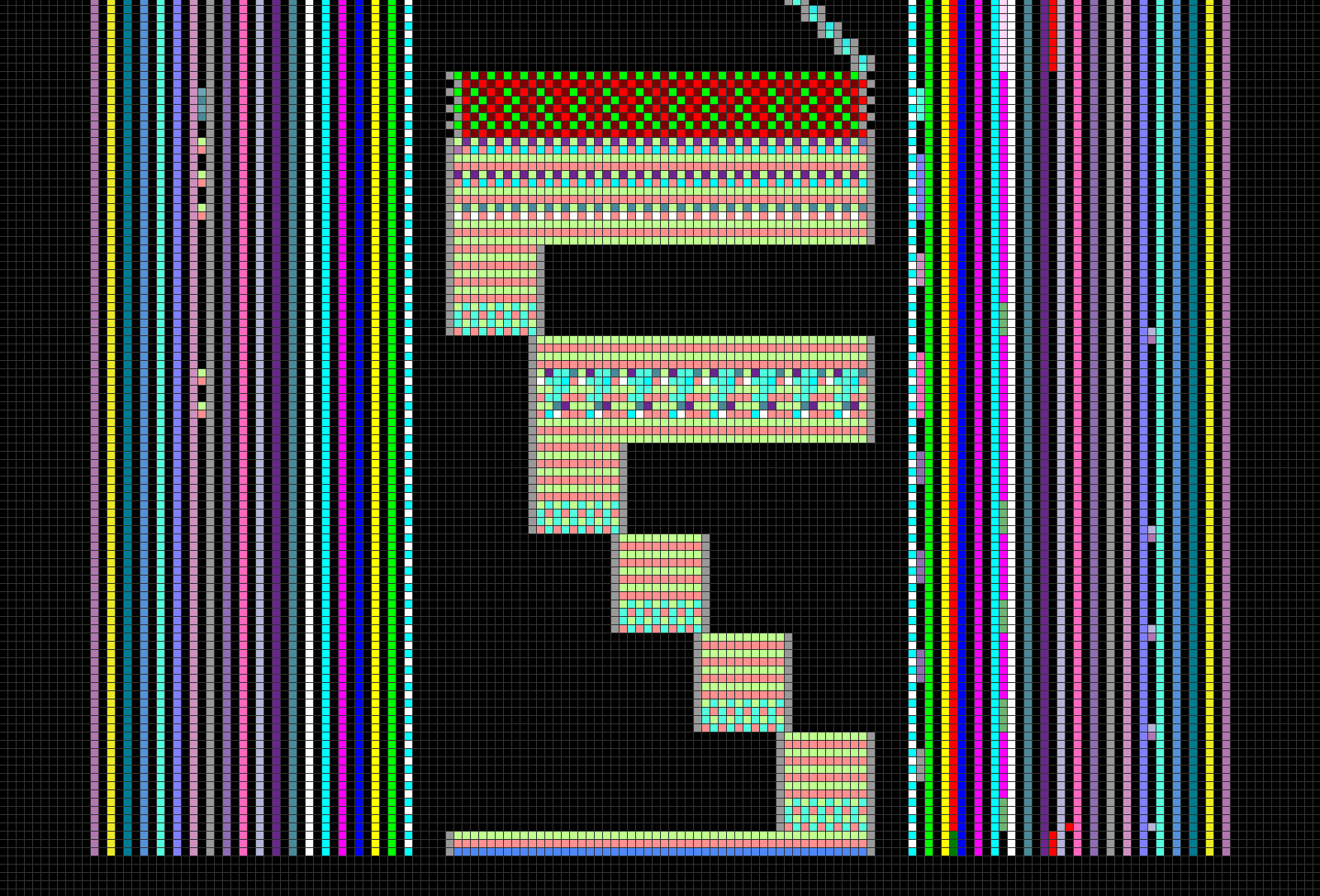
These machines are capable of creating whole garments with full customization, but unfortunately their programming is complicated and requires skilled experts. Low-level machine programs are typically represented as colored needle-time images (Figure 8) whose pixels are per-needle operations that get compiled into machine instructions. Existing commercial softwares also provide garment templates with a set of customizable properties (width, length, etc.) for predefined shapes (such as gloves, hats, or sweatshirts). However, template parameters only modify the garment geometry (known as shaping); the surface texture and appearance (known as patterning) must be modified through separate tools, or by manipulating the local instructions generated from the template [28].
Our system unifies and simplifies these existing approaches within a single workflow, while trying to alleviate two of their original limitations: (1) existing templates cannot be composed, which limits their potential to a fixed set of predefined shapes, and (2) these templates lack a bidirectional decoupling between shaping and patterning, so any alteration of shape parameters requires recreating the associated patterns.
We propose an interactive system to compose parameterized knitting primitives similar to knitting templates, while ensuring knittability and allowing continuous user customization of both garment shape and patterns. The contributions of our work include:
-
•
A web interface for creating and customizing knitting templates for everyday garments
-
•
A domain specific language for patterning
-
•
A novel layered pattern representation with different resampling behaviours for decoupling shapes and patterns
Furthermore, we release our web interface and its source code to allow the democratization of computer-aided knitting. See the project page: http://knitskel.csail.mit.edu.
2 Background and Related Work


We begin with a brief overview of knitted fabric and the mechanisms of the knitting machine we use to create it.
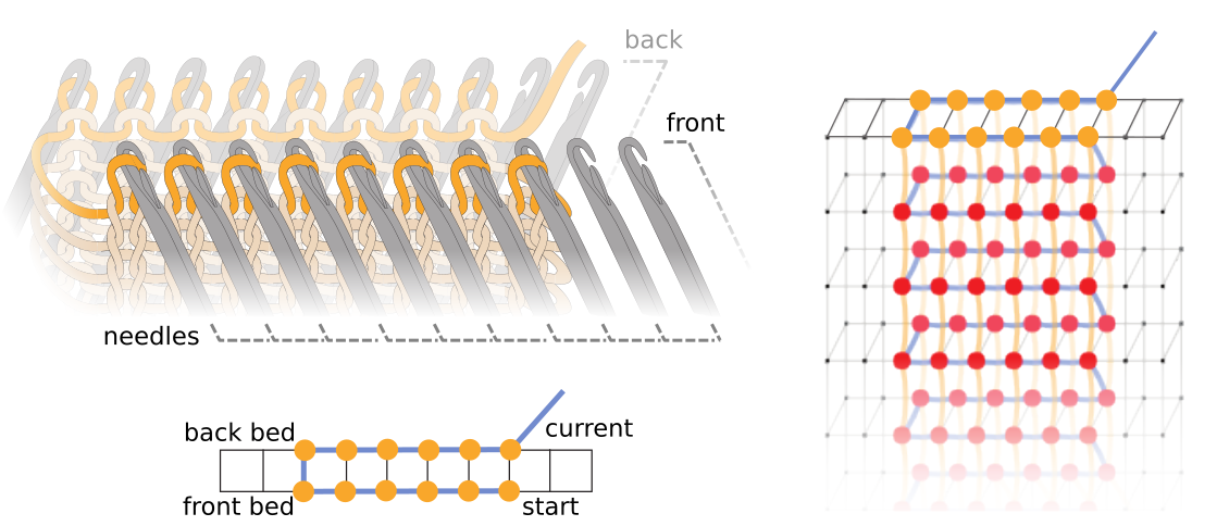
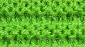
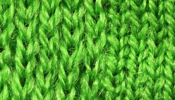
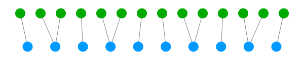
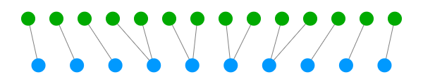
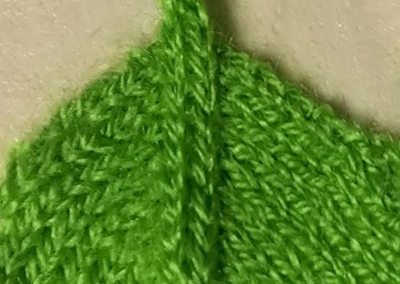
The smallest unit of knitted fabric is a stitch (as illustrated in Figure 2). Typically, a stitch is created by pulling a yarn loop through a pre-existing stitch; this new loop is later stabilized by having another stitch pulled through it. The neighborhood of each stitch defines the local topology of the fabric, and must fulfill certain criteria to prevent the fabric from unravelling. In this work, we refer to rows of stitches as courses, and columns as wales. Every stitch has two course neighbors, except when the yarn starts and ends. Regular stitches also have two wale neighbors: the preceding stitch it was pulled through, and the subsequent one that stabilizes it. However, irregular stitches have more or fewer wale connections due to increases, decreases, or the yarn’s start and end.
Our system is targeted at knitting garments on weft knitting machines. In particular, we target V-bed machines111This work uses a Shima Seiki SWG091N2 with 15-gauge needles., which consist of two parallel beds of stitch needles, angled toward each other in an inverted shape. Individual needles can hold multiple loops of yarn in their hook, as illustrated in Figure 3. They can be actuated as one or multiple carriers bring yarn over the beds. The main per-needle operations include knit which pulls a loop of yarn through the current ones, tuck which adds an open loop in the needle hook, and miss which moves the yarn without triggering the needle operation. Furthermore, each needle on a given bed has a counterpart that is directly across the gap, on the opposing bed; these needle pairs can perform a loop transfer, which moves a loop from one bed to the other. Although the needle positions are fixed within each bed, the lateral offset between the two beds (known as racking) can be manipulated. Thus, the counterpart of a given needle can change. By combining racking and transfers, loops are able to move laterally along the beds. For a detailed review of how these machines work, we refer the reader to the knitting reference by Spencer [29], the thesis of Underwood [32], and the algorithmic review of McCann et al. [17].
2.1 Knitting As A Service
Current industrial knitting machines are expensive. Although maker projects have attempted to create low-cost versions [25, 26], we still would not expect users to own such machines because they require expertise to operate. Just as manufacturing-grade 3D printing is generally not done at home but through a 3D printing service222 See https://www.shapeways.com/. , this work follows a recent vision of knitting as a service333 See https://ministryofsupply.com/, https://unless.me/. , in which users send their knitting jobs to a company, which then ships back their customized knitted product. This requires a means for the user to specify their custom-made garment, which motivates our work.
2.2 Knitting 3D Meshes
Several early works have tackled the problem of converting a 3D mesh to hand knitting instructions such as for plushes [10, 11]. More recently, Narayanan et al. [18] tackled the automatic machine knitting of 3D meshes, and posited a theoretical description of machine knittable structures 444Note that machine knittability, which we require, is more constraining than hand knittability.. This description motivates our shape skeleton.
We avoid the external 3D modeling step, by building a CAD system for whole garment knitting in the traditional sense, where we assume modeling is done from scratch. The first motivation is that the primitives for garment knitting are less various than the diversity of topologies that can be represented by general 3D meshes. The second reason is that surface patterning requires specifying knitting patterns on top of the shape. Texture mapping could allow this on meshes, but it introduces several unnecessary challenges [40] and tightly couples the pattern with the shape. Instead, we seek to decouple shape from pattern; thus, we use a novel layered pattern representation for general graphs.
2.3 Shaping Primitives
McCann et al. [17] built a similar CAD-like approach, with a language and algorithm for the machine knitting of general tubular shapes. One of their contributions was the time-needle bed visualization (see Figure 4), which we build upon. They also introduced machine knitting building blocks (e.g. sheets, tubes, short rows), which are manually instantiated onto the time-needle bed. Our system uses similar building blocks, but provides automatic bed layout. Additionally, we tackle the problem of surface pattern customization while allowing the continuous editing of both shape and pattern.
2.4 Modeling Garments and Patterns
Multiple works have looked at modeling the garment making process. Sensitive Couture [31] tackles the specification of sewing patterns for woven structures. Other works focus on modeling the yarn directly on top of specialized structures such as stitch meshes, with applications in realistic rendering [12, 39]. More recently, these have been translated to hand knittable structures [37, 38]. We build upon a similar stitch unit as theirs, but do not use 3D meshes. Instead, we use a multi-layered 2D embedding that enforces machine knittability and allows pattern design similarly to image editing. This allows us to reuse the plethora of manually-codified pattern recipes [7, 5], as well as those directly inferred from images [13].
2.5 Parametric Design
Our system takes inspiration from traditional CAD softwares, together with novel systems that they have inspired. One example is Robogami [27], which combines custom-made robot components for easy fabrication. Similarly to the shape- and volume-authoring tools Antimony [14] and Foundry [34], we use composable primitives, and a pattern representation based on short function expressions that can be modified by the user.
2.6 Domain Specific Language
Various Domain Specific Languages have been designed to tackle dedicated problems, such as shade trees [6] for rendering, or Lindenmayer systems [22] for generating complex structures. More recently, the Knitout language [17] proposes a set of low-level instructions and a compiler dedicated to making machine knitting independent from the machine target. Another recent set of instructions [13] targets machine knitting of patterns. We introduce a patterning DSL that employs this last instruction set within a two-stage process (select + apply) inspired by the dataset visualization language, D3.js [3].
3 Knitting Skeleton Overview
In this section, we present a typical workflow session, and then elaborate on several individual components and features of our system. The following sections detail the shaping primitives and patterning DSL, before discussing our user feedback and results. For interactive sessions, please see the project page.
3.1 Typical Workflow
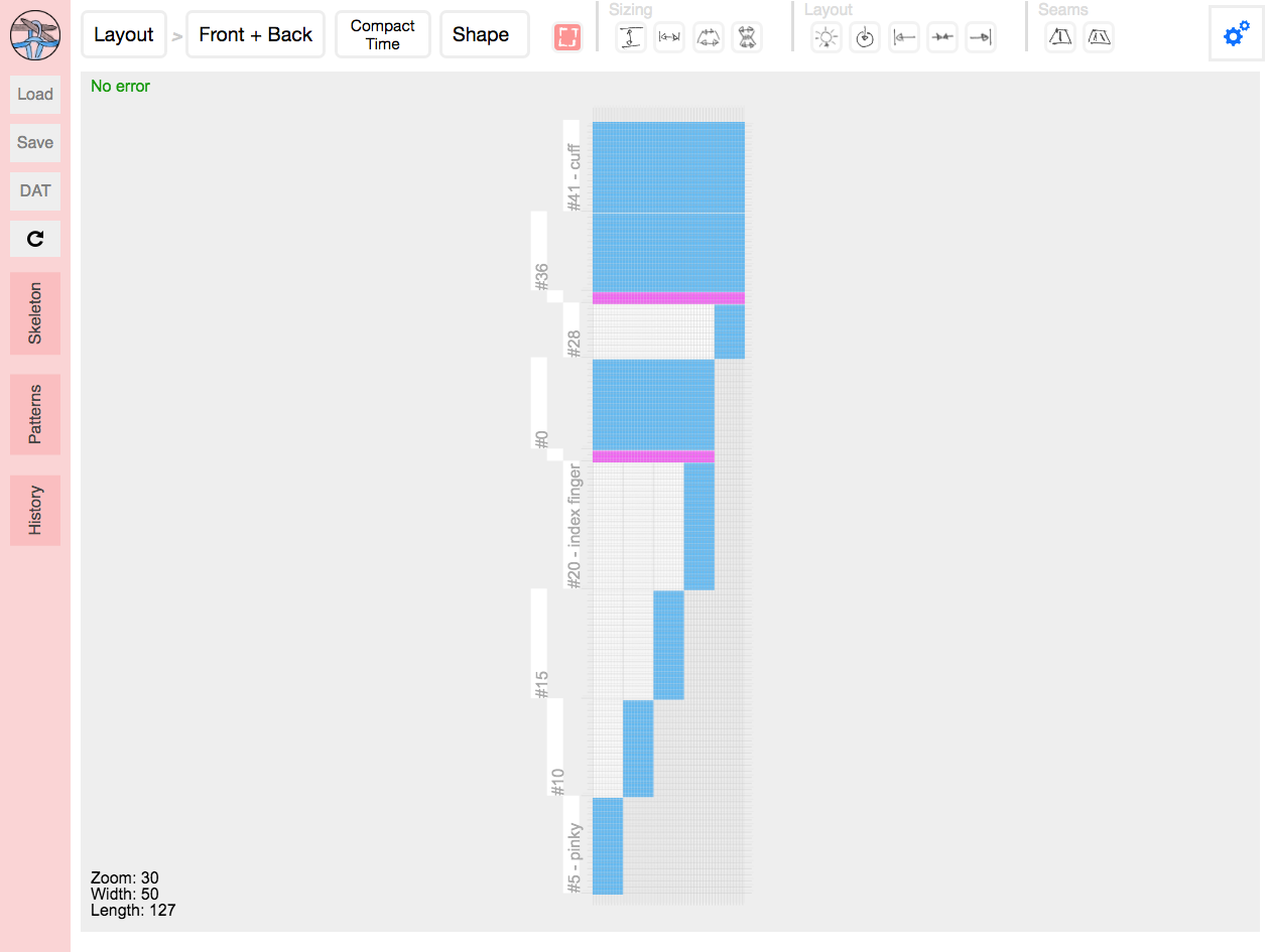
Our user starts from a base shape primitive (flat or tubular sheet) and modifies its shape parameters (e.g. size, layout, seams) by interactively manipulating them on the time-needle bed (Figure 4, detailed below). These interactions include dragging primitive boundaries for sizing, as well as dragging layout elements to change their location.
The user can also use a contextual menu to directly edit all exposed properties. In the global context (no shape selected), users can create new shapes and define user parameters (such as a glove’s base finger length). While hovering over a shape primitive, users can rename it, delete it, or edit any of its properties. Finally, by clicking on a shape boundary (called an interface), the user can "extend" the given shape by connecting it to an available interface with valid matching parameters, or by creating a new primitive (which will automatically connect to the selected interface, and assume matching parameters).
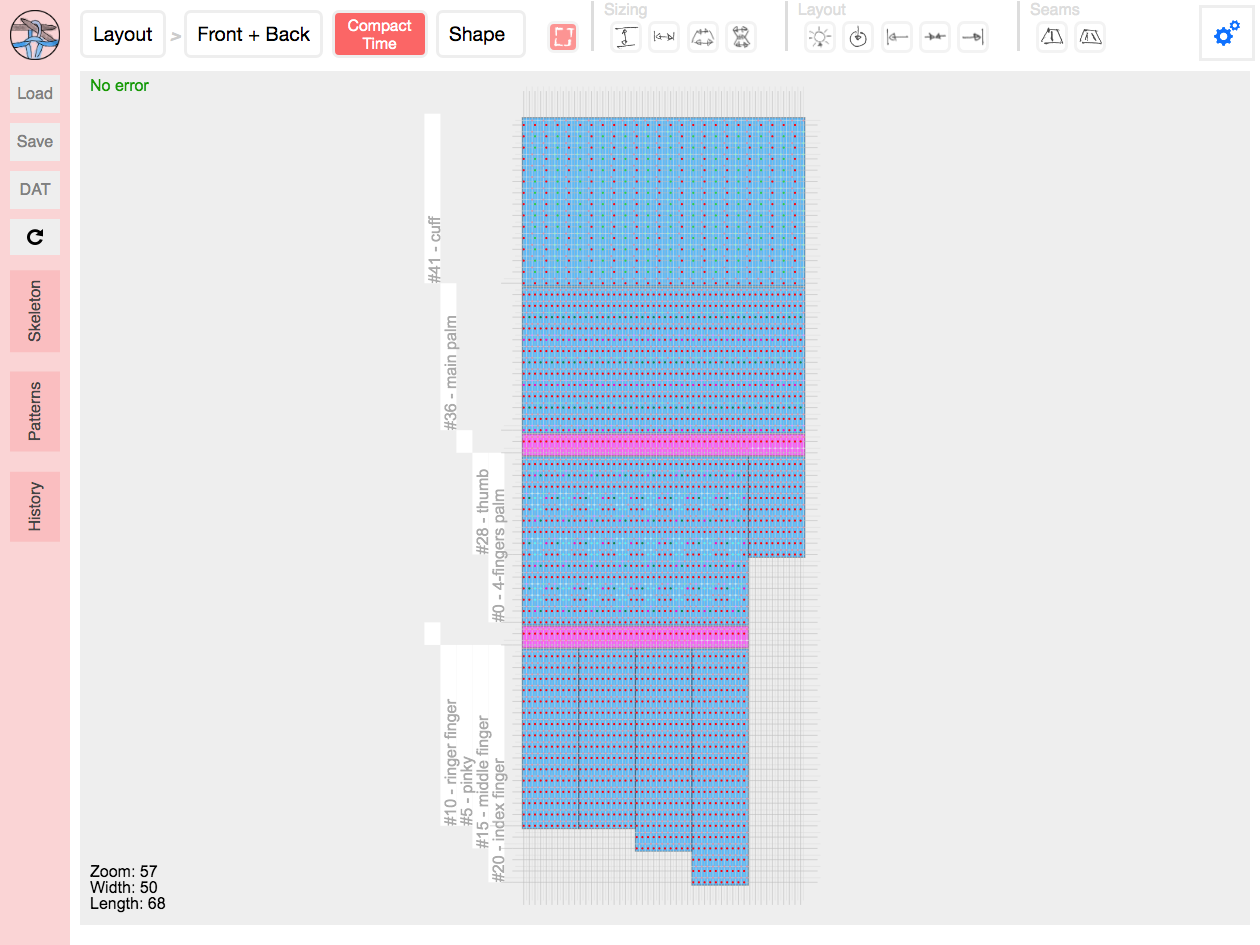
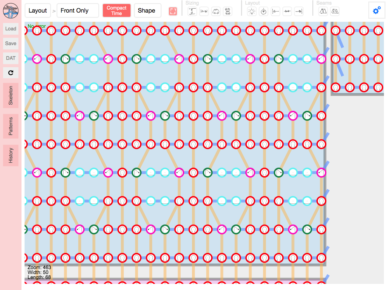
After creating the desired shape, the user switches to the pattern editing mode, where the toolbar actions affect individual stitches. In this mode, the user can either (1) draw the desired pattern directly onto a shape primitive, similarly to a pixel editing program, or (2) write pattern programs using our DSL in an editor. As the user zooms in/out, we display varying levels of information, including the type of pattern operation, and the local yarn topology (course and wale connections).
Finally, the user can visualize the yarn structure with a force layout tool, save the resulting skeleton, load a new one, or inspect and export the necessary machine code.

3.2 Shape Skeleton
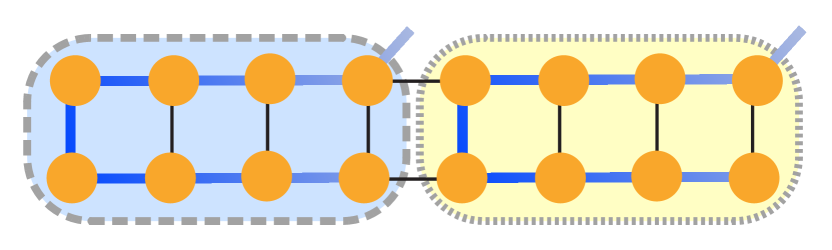
The recent work of Narayanan et al. [18] showed that any shape whose skeleton can be drawn on a plane without self-intersection can be machine knitted. This motivates our underlying shape representation, which is a skeleton graph whose nodes are shape primitives, and edges are connections between node interfaces, as illustrated in Figure 5. The garment shape is defined by the node types, connections and parameters. The final surface pattern is defined by pattern layers associated with each node, and applied on the stitches locally. Together, these produce the final knitted structure.
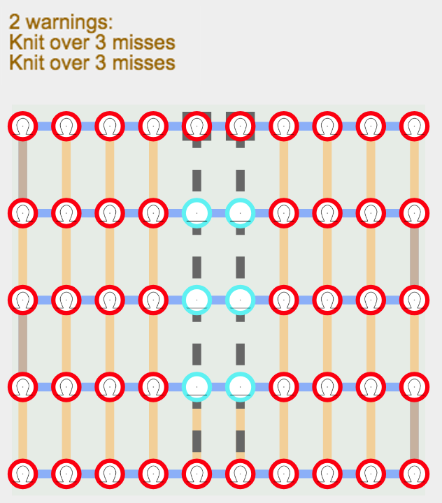
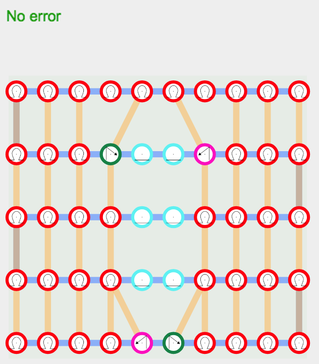
By construction, our shape primitives allow for a continuous yarn path within each node and across interfaces, thus ensuring knittable skeletons. However, issues can still arise since (1) shape parameters across interfaces may be in conflict (e.g. different widths), and (2) user patterns may produce unsound structures or put excessive stress on the yarn. We identify such problems, but we do not fix them, because there is typically no “correct” solution without knowing the user’s intention. Instead, we issue warnings (detailed later), and let the resolution to the user.
3.3 Time-Needle Bed
The main visualization onto which the shape skeleton is composed is the time-needle bed. This is a common representation for machine knitting [28, 17], illustrated in Figure 4. The actual bed layout is automatically computed as the user extends or modifies the underlying skeleton. This representation has two advantages: (1) it directly shows the time process followed by the knitting machine, which allows us to produce interpretable warnings if the user creates undesirable knitting structures (see Figure 6), and (2) it introduces a grid regularity, which allows the user to draw complex patterns in a manner similar to layered image editing.
3.4 Yarn Interpretation and Simulation
Our system interprets the yarn path through time to provide warnings and errors to the user as they create their shape and combine patterns, as shown in Figure 6. The main issues we catch are (1) unsafe yarn tension prone to yarn breakage, (2) too many yarn loops on a needle, risking pile-up or failed operation, and (3) reverse stitches when the opposite bed is occupied (e.g. in full-gauge tubular knitting). We provide feedback both textually with the types of issue and potential fixes, and visually by highlighting the problematic stitches together with their conflict dependencies.
We also provide a force-layout graph simulation [33] as an approximate preview of the yarn deformation after knitting, as illustrated for a glove in Figure 7.

3.5 Low-Level Machine Code
Finally, we provide a view to inspect the low-level code that is generated for the current layout, as illustrated in Figure 8. This allows experienced designers and machine operators to inspect the actual program used by the machine.
4 Shaping Primitives
Each of our three knitting primitives (Sheet, Joint, and Split) play a specific role in the garment’s final shape. We detail each primitive and its properties, then provide more details on our skeleton editing paradigm.
As skeleton nodes, all primitives have a name (for visualization and pattern references), a pattern, and a gauge, which we detail in the next section. All nodes also define a set of interfaces which can be connected to other nodes.
4.1 Sheet / Tube
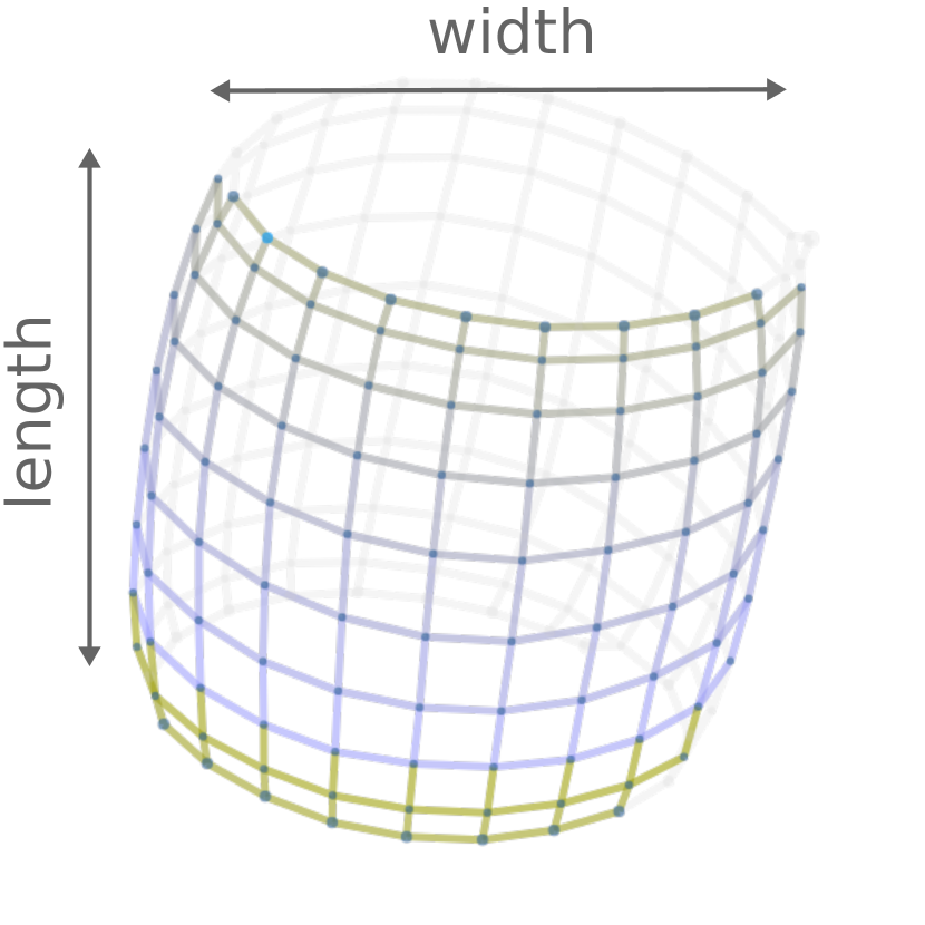
The Sheet primitive is the base component for knitting any flat or tubular structure. Its two main parameters are its length, defining the number of courses making up the sheet, and its width, defined over the length. While the default configuration is a regular rectangle (sheet) or cylinder (tube), users can create more interesting shape profiles through stitch increases and decreases (illustrated in Figure 2). These modulate the number of stitches on consecutive courses, in order to grow and/or reduce the shape over the bed. At a high-level, the user can modulate the width as a piecewise linear function over the normalized length interval , yielding non-rectangular profiles. If desired, the user can also customize the stitch-level shaping behavior (i.e. placement of stitch increases and decreases) using one of multiple predefined behaviours, or a user-provided function that specifies how to allocate wale connections when changing the course width. We provide details for these functions in the supplementary material, including examples of how the shaping behaviour affects the appearance of the yarn with the location of seams. The primitive layout can be customized by choosing a specific alignment, which impacts both the bed layout and the yarn stress distribution. This primitive has two interfaces: the top and the bottom.
| Property | Values |
|---|---|
| Type | Flat, Tubular |
| Length | Integer |
| Width | |
| Shaping | Uniform, Sides, Left, Right, Center, Custom |
| Alignment | Left, Right, Center |
| Bottom | Interface |
| Top | Interface |
4.2 Joint
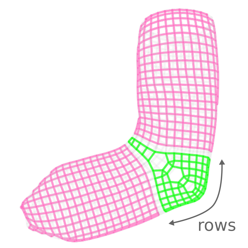
Our Joint primitive captures the second shaping process, called short rows, which only knit across a subsection of the current course, while suspending the other stitches. These partial rows induce bending in the structure, as in a sock heel. A Joint represents a collection of such short rows. The user can specify the number of short rows, the width of each, and their respective alignment. Users can also specify a layout, which controls the normalized location of short rows along the interface boundaries, i.e. their offset for flat knitting, or the rotation for tubular knitting. The interfaces are the same as for the Sheet primitive.
| Property | Values |
|---|---|
| Rows | Integer |
| Width | |
| Layout | or "auto" |
| Alignment | Left, Right, Center |
| Bottom | Interface |
| Top | Interface |
4.3 Split / Merge
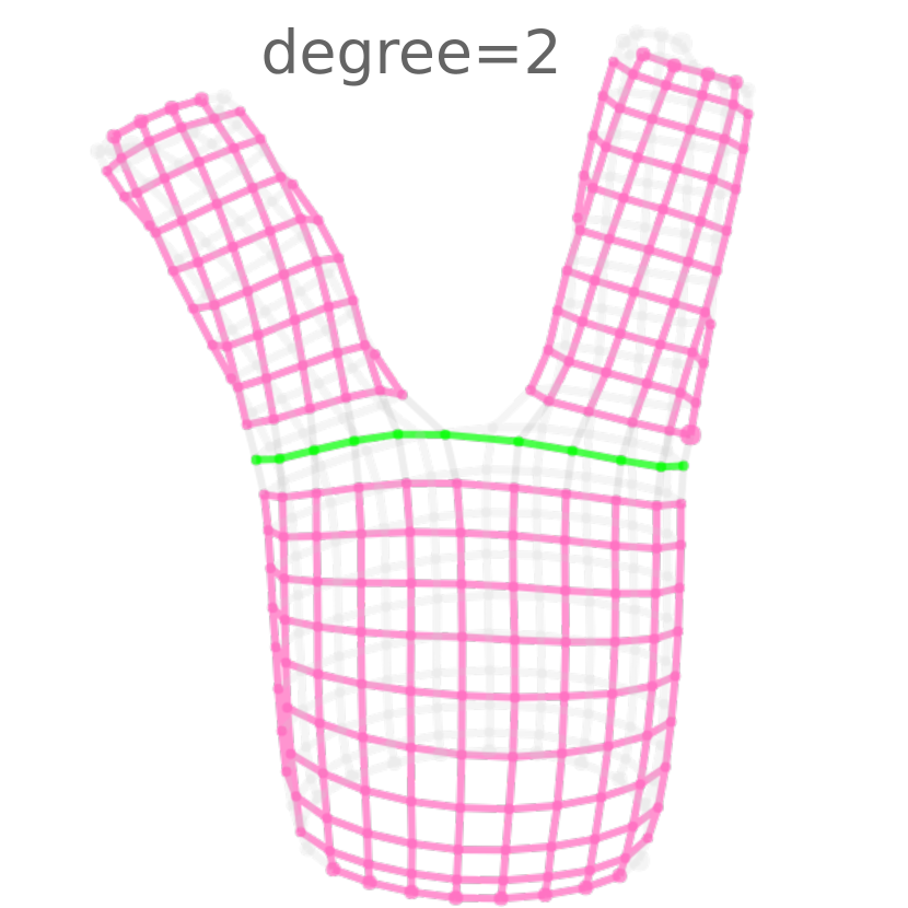
Finally, our Split primitive allows for more complicated structures (like gloves) that require topological branching and/or merging. It merely consists of a base interface and a set of branch interfaces. It has a branching degree together with a branch layout. For automatic layouts, the user can also provide the branch alignment. Furthermore, for tubular bases, the branching can be folded (tubular branches) or not (flat branches) as illustrated in Figure 12. Flat bases only allow flat branches. Finally, since the interface connections are not restricted in any direction, this primitive can be used both to subdivide an interface or to merge multiple interfaces.
| Property | Values |
|---|---|
| Degree | Integer |
| Layout | or "auto" |
| Alignment | Uniform, Left, Right, Center |
| Folded | True or False |
| Base | Interface |
| Branches | List[Interface] |

4.4 Editing Primitive Parameters
Our system allows multiple interaction strategies. One can work exclusively with the abstract skeleton graph, and edit parameters using a tabular inspection panel. Alternatively, one can drag the mouse to interactively extend the shapes on the bed layout. In this approach, more complicated parameters can be specified using the contextual menu that allows the same fine-grained control as the tabular parameter panel.
When specifying parameters through the input panel or the contextual menu, the user can enter either direct numbers, or #expressions that introduce global design parameters. These are global variables that can be reused across different inputs and node parameters, providing a means to expose important design parameters (such as a glove’s width or length scale). For example, the user could specify the length of a glove finger via (#Len + #LenDelta) which introduces two parameters, #Len and #LenDelta. Each of these could be independently applied for the other finger specifications, and any changes to the variable value would be reflected globally. These expressions can also refer to node properties with @prop. For example, the width of a sheet could be made equal to its length using the expression @length.
5 Patterning


| Category | Methods | Explanation |
|---|---|---|
| Filtering | all(), filter(pred) | Stitches that match a logic predicate |
| Sets | or(x,y), and(x,y), minus(x,y), inverse() | Standard operations on sets of stitches |
| Indexed | wales(rng), courses(rng), select(c, w) | Indexed stitches within a range |
| Neighborhood | neighbors(rng), boundaries() | Stitches at some distance from selection |
| Named | named(), shape(name), itf(name) | Stitches located by a named entity |
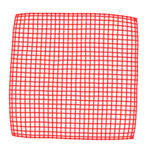
| Masking | stretch(grid), tile(grid), img(src) | Stitches that match a given grid mask |
Given a shape skeleton, our system assembles stitches for each of its nodes, and then merges stitch information at the interfaces, producing a stitch graph whose nodes are individual stitch units (see Figure 2). Initially, the stitch connections (course and wale) are defined by the shape primitives. Each stitch also includes a pattern operation that describes how to modify the stitch with respect to its surrounding neighborhood. These operations allow the user to design special surface textures and appearance on top of the shape.
5.1 Pattern Operations
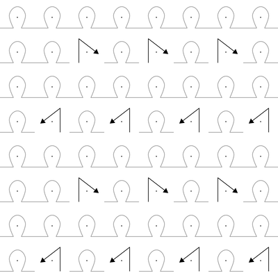
For the pattern operations of each stitch, we use the instruction set of Kaspar et al. [13]. The main difference is that we apply those instructions not on a one-sided regular grid, but on the stitch graph, which is then projected back to the time-needle bed to generate the final low-level machine code. Figure 13 illustrates the types of pattern operations we support.
Importantly, our pattern operations do not create or delete stitch units. Instead, they modify how individual units are interpreted, either by providing a different operation to the target needle (purl or tuck instead of the default knit), or by altering the wale connections (miss, move and cross). In the case of miss, any previous wale connections of the missed stitch are transferred to the subsequent one. Move and cross operations change the subsequent wale connection to a neighboring one along the next course.
If a neighboring wale target does not exist (e.g. at the border of a flat sheet), then the operation is not applied. Note that courses of tubular sheets are treated as cyclic, so a neighboring wale connection always exists (possibly on the other bed). The system ignores move and cross operations on irregular stitches (increase/decrease) to ensure structural soundness.
5.2 Patterning DSL
To apply pattern operations on the stitch graph, we designed a domain specific language in which the user first specifies a subset of stitches of interest – the query – onto which they can apply a given patterning operation.
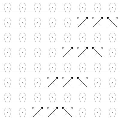
Our types of queries are listed in Table 1, and a subset is illustrated in Figure 14. The main query is filter, on which all other queries are based (with some specialized implementations to improve speed).
Initial
Range of wales
…of courses
Area select
Union
neighbor
img mask
tile mask
Filter with noise
5.3 Drawing Layers
All our patterns are synthesized using our DSL. We split the pattern specification into a sequence of layers: (1) an initial global layer spanning all stitches, (2) varying sequences of per-node layers modifying stitches of specific nodes, and (3) a final global layer. By default, all base layers are empty and we assume the base pattern is a standard knit stitch.
Users can write their own program, use pre-existing ones, or interactively draw node pattern layers in a manner similar to image editing softwares that allow pixel-level modifications. We preview the impact of the patterns on the wales, as illustrated in the right of Figures 4 and 6, where move operations displace the upper wale targets.
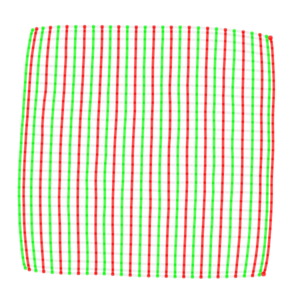
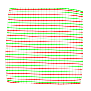
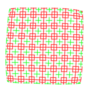
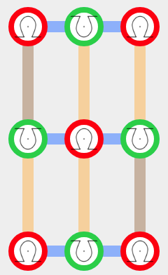
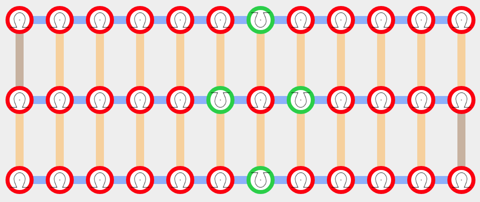
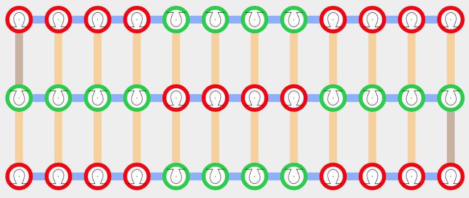
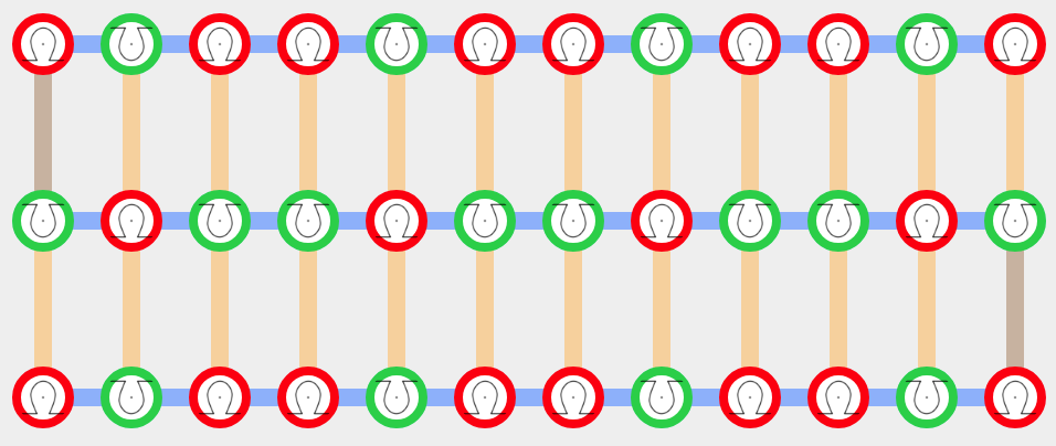
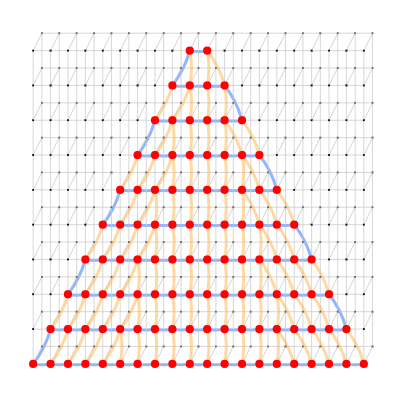
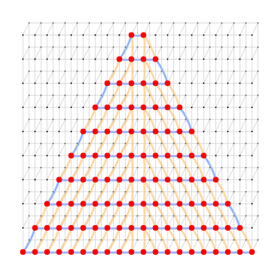
Our pattern layers can be exported, imported and resampled for different shapes and sizes. The resampling behaviour can be specified by using different types of layers. We provide three pattern drawing types – singular, scalable and tileable – whose behaviours are illustrated in Figure 15.
5.3.1 Singular Layers
This is our default drawing mode, which does not resample the initial pattern, but simply modifies its location to account for the change in size (e.g., by centering the original pattern).
5.3.2 Scalable Layers
These layers resample their pattern by nearest neighbor resizing. In this mode, we do not allow cross operations, which are coupled in paired groups and typically applied with a limited local range constraint to prevent yarn breakage.
5.3.3 Tileable Layers
These layers resample their pattern by applying a modulo operation so as to create a tiling of the original pattern.
5.3.4 From Drawings to Programs
Drawings are stored as semi-regular grids of operations, which can be empty (for no operation, the default). To apply the drawing, we transform it into a basic program that makes use of the drawing data together with a resampling function depending on the type of layer. Singular layers relocate the drawing information, whereas scalable and tileable layers use the stretch and tile functions, respectively.
5.4 Half-Gauge Knitting
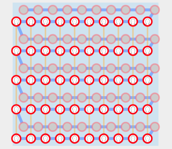
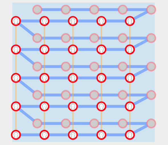
For each primitive, the user can choose a desired gauge (either full or half). This property is important because pattern operations that modify the side of the stitch operation (regular vs reverse, or “purl”) can only occur on a given stitch if the needle directly across from it (on the opposite bed) is empty. In the case of tubular fabric, the opposite bed holds the other side, which can lead to conflicts. In such case, half-gauge knitting is a typical solution, which consists in knitting on every other needle, with both sides offset such that any needle’s counterpart on the opposite bed is empty, as shown in Figure 16. Note that the need for half-gauge depends on both the shape and the pattern. Even if it is unnecessary, it may still be desirable because it creates looser fabric. Thus, we do not automatically choose which gauge to use, but let the decision to the user. For full-gauge primitives, we detect conflicting patterns and show a warning to suggest switching gauge.
6 Results
Our first results explore the range of garments that are machine-knittable using our shaping primitives. We then consider the use of our different pattern layers, and their behaviors as node parameters change.
6.1 Span of Shaping Primitives
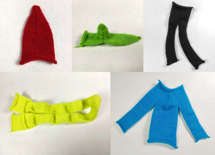
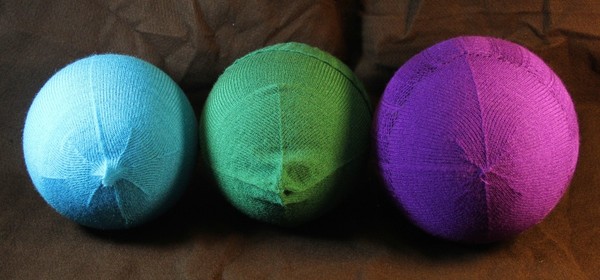
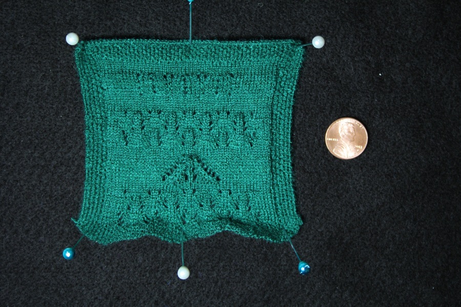
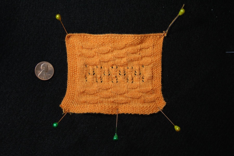
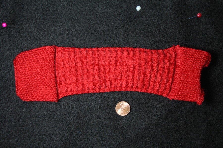
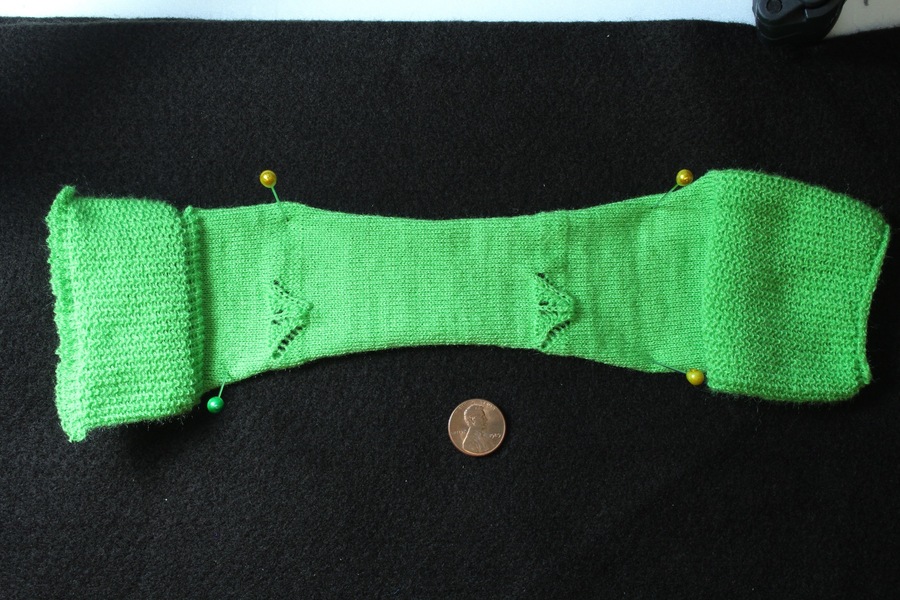
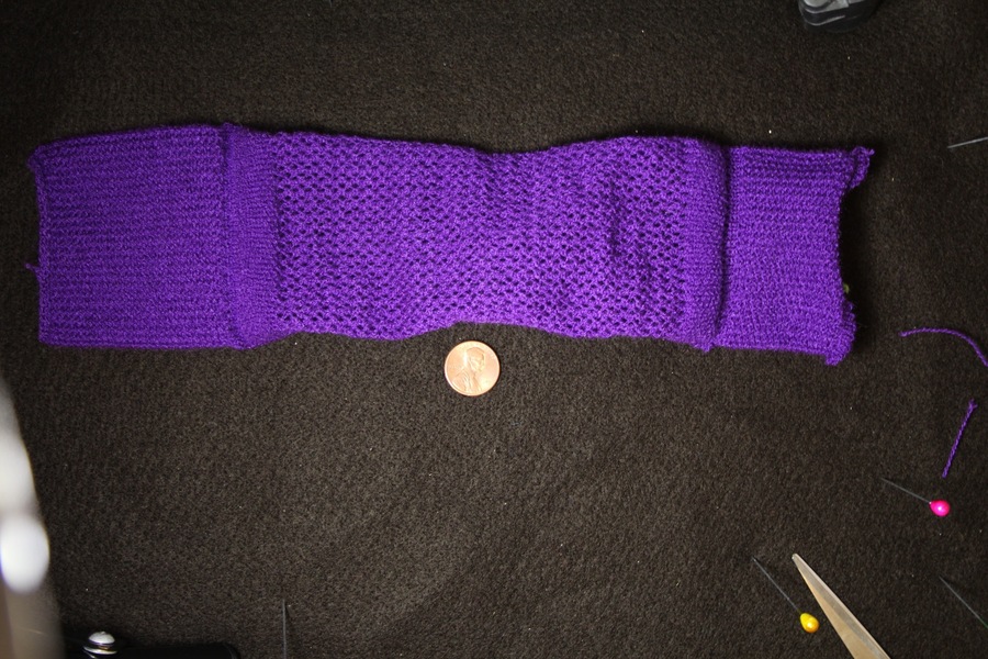
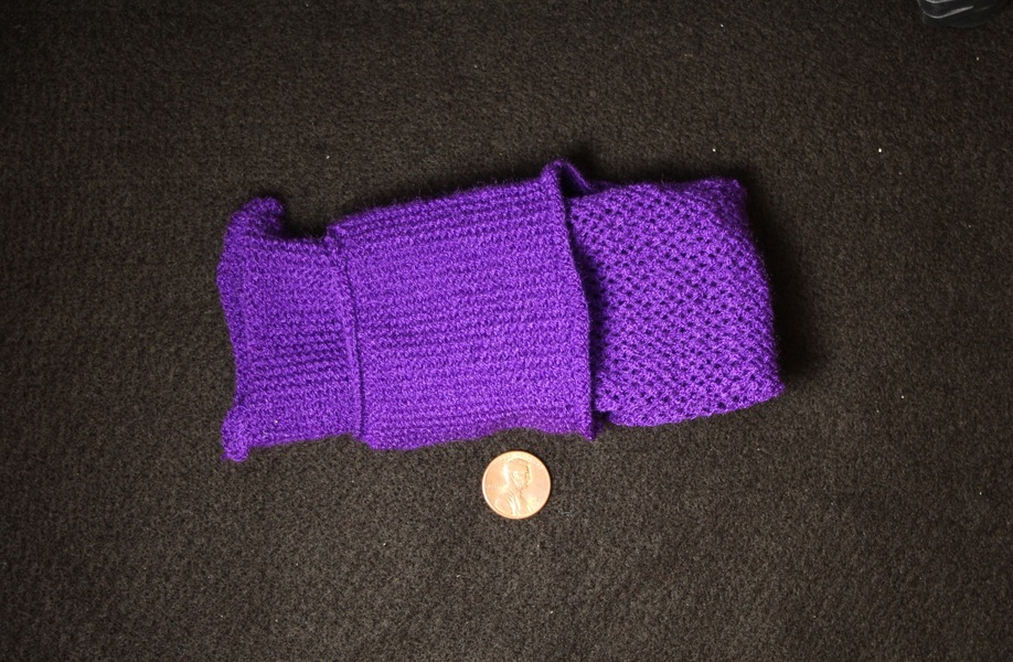
Our first collection of knitted results is illustrated on the 12 inch mannequin shown in Figure 1, together with adult-size versions of a patterned infinity scarf and a ribbed sock. We show the individual pieces in Figure 17, each knitted with a different yarn color. This includes:
-
•
a hat using one cylindrical sheet with a narrow closed top and a wide open bottom;
-
•
a scarf with pocket ends, using one main flat sheet and ends that are split-converted into cylinders (one end is open to let the other end through, and the other is closed as a pocket);
-
•
a yoked shirt using one open tube split into three tubes (two for the sleeves, one for the main body);
-
•
sweatpants as a waist tube with a split branching into two tubular structures;
-
•
two socks using a joint for the heel and two tubes, one of which narrows down to the toes where it closes.
6.2 Pattern Layers in Action
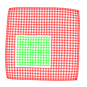
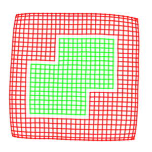
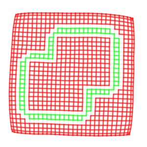
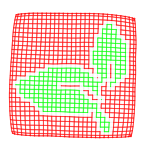
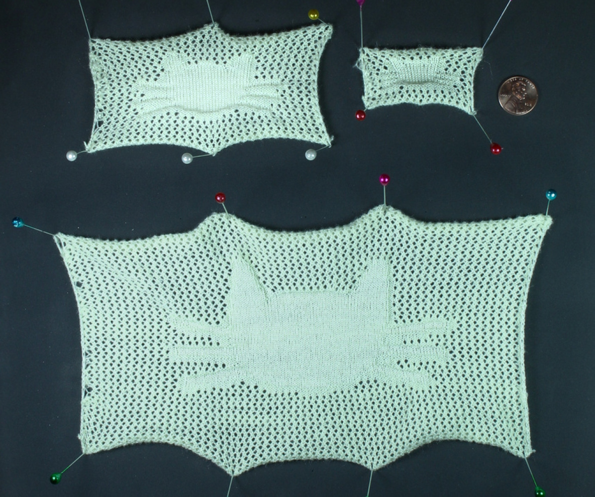
The top part of Figure 19 illustrates how shape modifications alter two overlapping patterning layers. The background consists of a tileable layer repeating a sequence of left and right moves to create lacy holes, whereas the foreground is a scalable image mask applying normal knit stitches. As the sheet size changes, the layers behave differently: the background keeps tiling the same small move sequence, whereas the cat foreground expands with the size. The bottom part illustrates an extension that includes a pure program layer for the margin, and two complementary scalable foregrounds layers with different stitch operations (knit and purls).
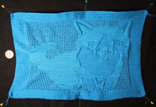
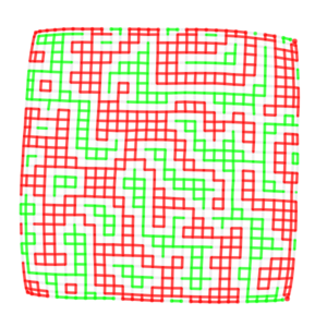
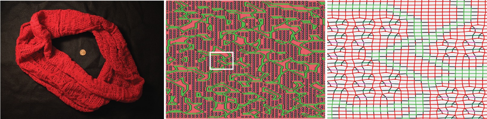
In Figure 18, we visualize the mesh of a patterned infinity scarf, which uses a layer decomposition similar to the tiled lace. However, the tiled lace is applied within a program mask that makes use of 2D simplex noise to create a random area selection. Its boundaries are mapped to regular stitches within 2 stitches, and to purls from 3 to 4 stitches away.
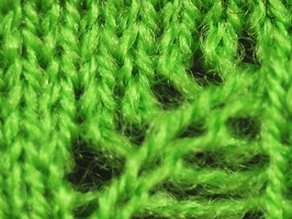
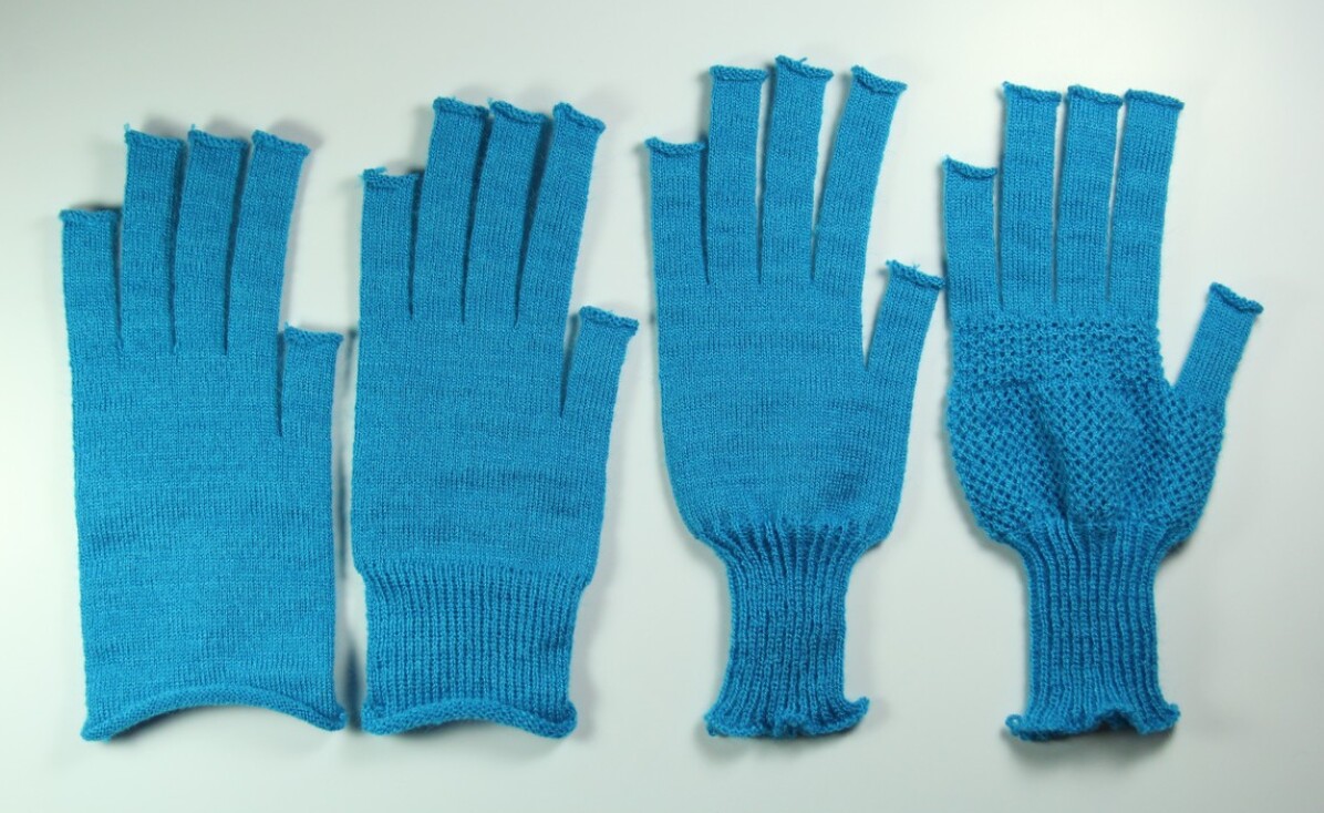
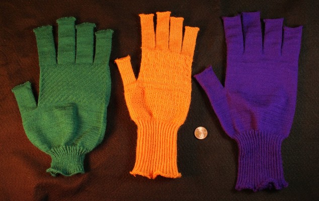
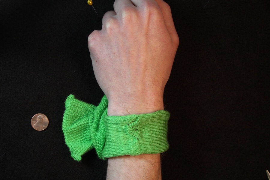
Then in Figure 20 we transfer the global hole pattern to two nodes of a glove skeleton with open fingers. This figure also illustrates the potential impact on shaping that some patterns have. Here, the cuff of the glove has a constant width that matches the palm node. The ribbed cuff shrinks considerably even though it is knitted over the same bed width (in half gauge). This is the same glove as in Figure 1.
7 User Experience
To verify that our interface could be used by non-expert users and receive important feedback, we asked two potential users without prior knitting experience to use our system.
7.1 Procedure
The users were provided a minute introduction to the basic operations involved in machine knitting, including the notions of shaping and the types of stitches. We also supplied a few sample videos of expert user sessions, and an introductory document for our user interface. We asked them to complete a few tasks: the first ones about patterning, and the later one for shape and pattern customization.
7.1.1 Patterning Task
For the first subtask, the users were given a base skeleton with a single flat sheet, featuring an initial program pattern that flattens its margins (to prevent the single-sided fabric from curling up). Their task was to draw some additional patterns on the sheet.
In the second subtask, we provided examples of lace patterns, and asked the users to create their own lace involving at least a few move operations.
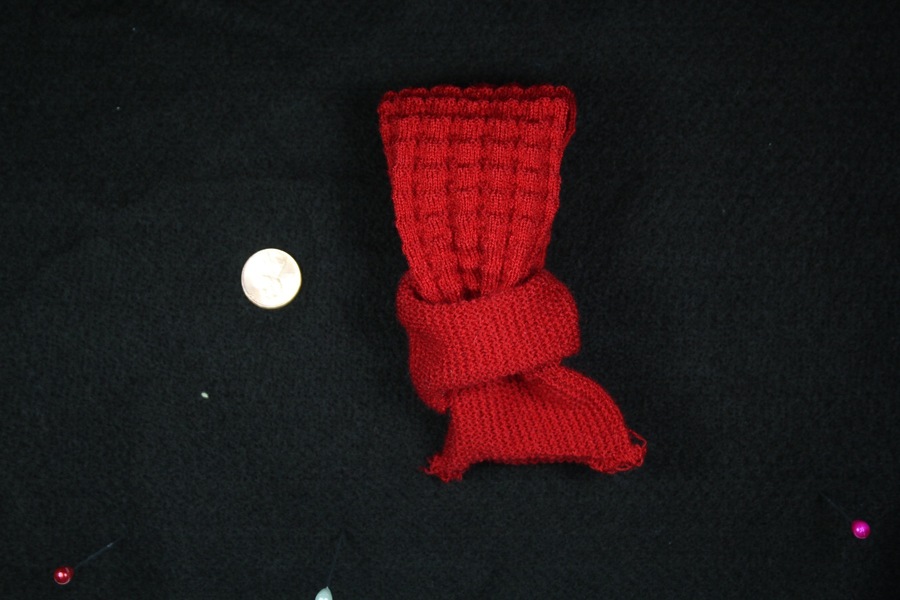
For the last subtask, we provided a more complicated template of a wristband, which is similar to the pocketed scarf in 17. The users had to import a pattern from their previous subtasks and apply it on the main part of the wristband. Please see the supplementary material for these results.
7.1.2 Shaping / Patterning Customization Task
The second task was to customize an adult-size garment of their choice, given an initial skeleton.
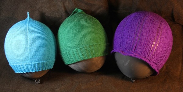
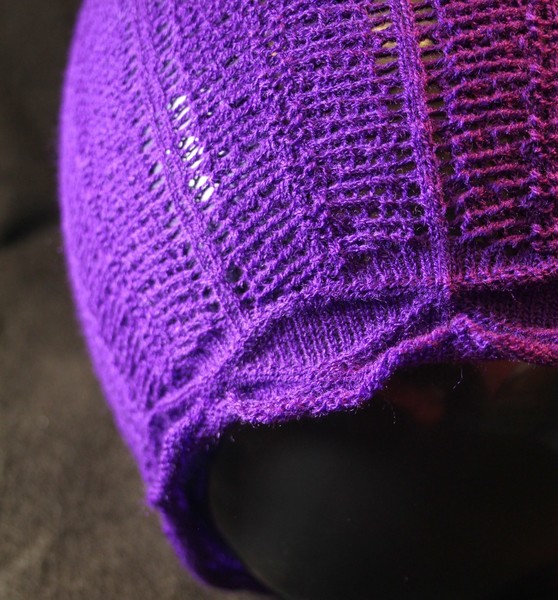
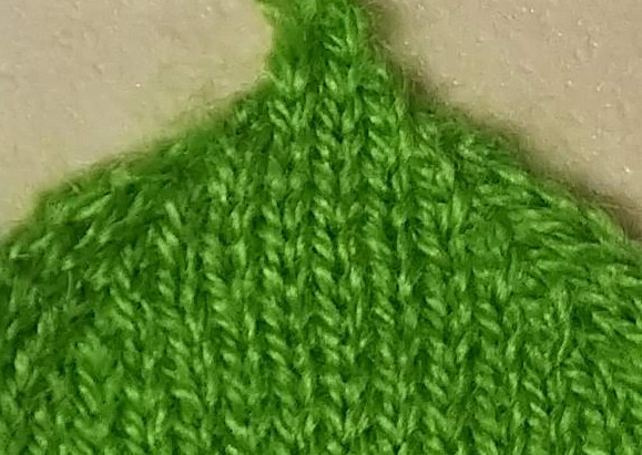
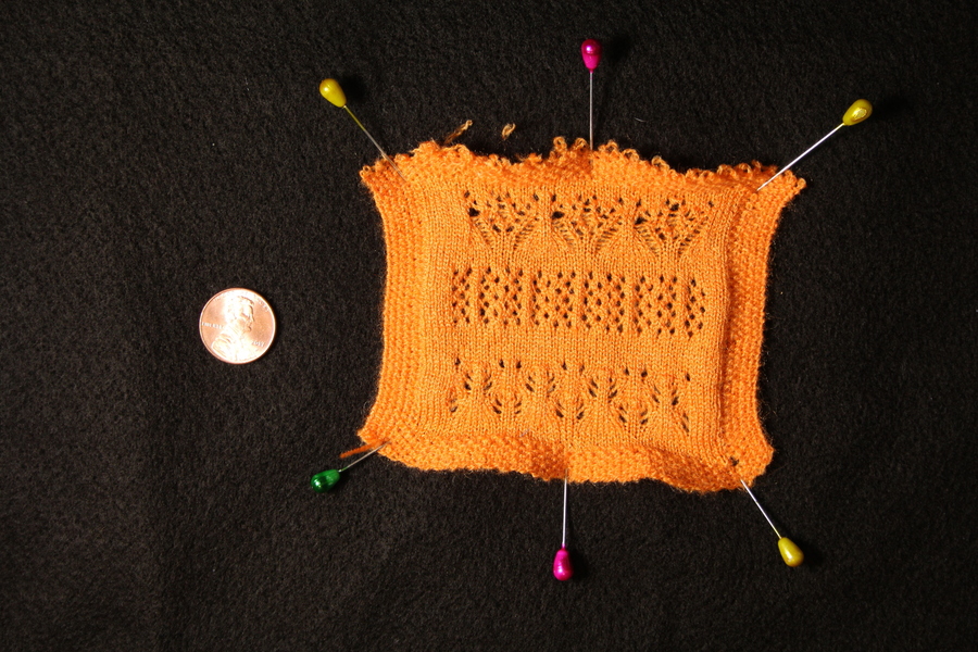
Our users chose to customize a beanie and a glove. For the beanie, users had to change the shape profile of the top section, and optionally modify the pattern of the brim or core sections. For the glove, the goal was to change global, shared design parameters (finger length and width, and/or cuff length) instead of directly changing the individual node widths. The corresponding results are shown in Figures 21 and 23. Figure 22 shows a closeup on the laced beanie and its brim.
7.2 Feedback and Results
Although none of the users had prior knitting skills, each one successfully designed sophisticated, machine-knittable structures that we were able to fabricate. Users were surprised by their new ability to customize garments, especially larger ones (e.g., the beanie).
During the design process, users cited a mismatch between their perception of the garment size (based on our bed visualization), and size of the actual knitted result. This suggests that, beyond local editing, it may be worth tuning the relative size of wales and courses to perceptually match that of the real yarn. However, realistic sizing is an open problem, as current tension parameters are hand-tuned and must be adapted for complicated patterns (e.g., changing the tension impacts the garment size substantially). It will require a better simulation that takes the yarn tension into account.
Our users generally found the patterning interface intuitive, as the image editing analogy was sufficiently familiar. Still, it was difficult for them to reason about the ultimate effect of complex lace patterns. Eventually, they discovered that the mesh simulation was more helpful to preview the pattern impact, and made extensive use of it. They alternated between the two views (layout and mesh). Furthermore, one user found that complex skeleton constraints could hinder pattern experimentation. Instead, they preferred to design their patterns on separate, flat sheets, then import the design onto the final structure. These behaviours emerged organically.
Although our users were allowed to create new shapes, they did not actively try to do so in our task setup. This suggests that non-experts would likely prefer to start from templates. Our tool might also be valuable for professionals, designers and other expert users, but we have not validated such cases.
7.2.1 Knittability Constraints
Flat patterns were always knitted successfully on the first try. However, this was not the case for complex patterns on tubular structures, such as for the adult-size garments.
We show three result beanies, the right one having required multiple iterations to work properly. Our machine translation had very few issues, but some patterns triggered complications during the knitting process, mainly because of fabric pile-up, which arises from non-optimal yarn tension.
In the case of the gloves, all fully knitted from start without pile-up, but we discovered that the sequence of knitting had some unexpected impact on the yarn. Fingers are typically suspended on the bed before being knitted over to create the palm and one user decided to use complex patterns on the fingers themselves. This led to previous fingers being excessively stretched while suspended, and the yarn locally broke. Finding the appropriate tension was the main complication for both the patterned beanie and glove, which required a few trial-and-error attempts. We show the evolution of the green glove of Figure 23 in the supplementary material.
8 Discussion
We first discuss some of our design decisions, and then go over our system limitations, highlighting potential improvements.
8.1 Scope of Our Primitives
By composing three types of primitives (Sheet, Joint and Split), our design space already spans many common garments including varieties of gloves, socks, scarves, headbands, hats, pants and sweatshirts. The garments which we do not handle nicely are traditionally sewed garments such as pullovers with Raglan sleeves or drop shoulders. The general challenge is specifying continuous interfaces that glue primitives over multiple courses. We provide further details and an investigation of potential solutions in the supplementary material.
8.2 Smarter Pattern Layers
Our pattern layers are not guaranteed to behave nicely when resampled or applied to a shaped primitive. A “correct” behaviour is often ill-defined: for example, at the top of a vertically striped hat, should the stripes become thinner or merge together? Thus, it is reasonable to defer to the user in such scenarios, as we do. A different, recently proposed strategy [9] would be to adapt calibrated patterns to the local context.
8.3 Handling Multiple Yarn Carriers
We do not yet support multiple yarns on the bed at once (e.g., for intarsia). However we envision that such specification of the yarn can be done similarly to our patterning by additionally introducing a stack of yarn at each stitch. The main modification would be that yarn tracing would now also involve the specification and optimization of the different yarn interactions. This would allow not only intarsia but also functional fiber routing, yarn inlays, spacer fabric, and pockets.
8.4 Large-Scale Interactivity
Our system runs in a browser and can currently remain interactive with human-sized gloves, socks and beanies. Patterning or shaping full-sized sweaters or sweatpants is challenging because of their scale. Computationally, the garments require processing a very large amount of stitches. Their size also presents challenges for user pattern specification, as simple pixel-based operations are insufficient.
We expect to solve the computational challenge by using hierarchical data structures that do not instantiate all stitches but only the required information (e.g., at the boundaries or where the size changes). As for the design issue, we assume a similar hierarchical process would help. We envision using meta-patterns on higher-level stitch representations to be instantiated for the machine. Finally, recent patch-level pattern simulation [15] has shown promising interactive results.
8.5 Machine Independence
Currently, our system exports machine code for a set of specific machine targets (Wholegarment® knitting machines [28]). However, our design assumptions are that of general V-bed machines. Since our system uses very regular course structures, it should be easy to support exporting Knitout code [17], allowing us to potentially target other V-bed machines as well.
9 Conclusion
We presented a novel interactive system for composing knitted primitives that encompass a large variety of common garments. This work also introduced a domain specific language for patterning, along with novel pattern layers that enable pattern specification akin to image editing, complete with different resampling behaviours. Many works follow, including the support for multiple yarn carriers, which will allow more complex appearance and functional customization. We are also interested in optimizing the interactivity using hierarchical stitch representations, and providing more realistic simulation.
Acknowledgments
We would like to thank James Minor for the help with the paper and voice-over, Tom Buehler for the video composition, our external users Tim Erps and Mike Foshey for their time and precious feedback, as well as Jim McCann and the members of the Textiles Lab at Carnegie Mellon University for providing us with the necessary code to programmatically work with our industrial knitting machine. This work is supported by the National Science Foundation, under grant CMMI-1644558, grant IIS-1409310 and Graduate Research Fellowship 1122374.
References
- [1]
- [2] Lea Albaugh, Scott Hudson, and Lining Yao. 2019. Digital Fabrication of Soft Actuated Objects by Machine Knitting. In Extended Abstracts of the 2019 CHI Conference on Human Factors in Computing Systems (CHI EA ’19). ACM, New York, NY, USA, Article VS01, 1 pages. DOI:http://dx.doi.org/10.1145/3290607.3311767
- [3] Michael Bostock, Vadim Ogievetsky, and Jeffrey Heer. 2011. D3: Data-Driven Documents. IEEE Trans. Visualization & Comp. Graphics (Proc. InfoVis) (2011). http://idl.cs.washington.edu/papers/d3
- [4] Ann Budd. 2012. Knitter’s Handy Book of Top-Down Sweaters: Basic Designs in Multiple Sizes and Gauges. Interweave.
- [5] Butterick Publishing Inc. 2016. The Art of Knitting (Dover Knitting, Crochet, Tatting, Lace). Dover Publications.
- [6] Robert L Cook. 1984. Shade trees. ACM Siggraph Computer Graphics 18, 3 (1984), 223–231.
- [7] Nanette Donohue. 2015. 750 Knitting Stitches: The Ultimate Knit Stitch Bible. St. Martin’s Griffin.
- [8] Nur Al-huda Hamdan, Simon Voelker, and Jan Borchers. 2018. Sketch&Stitch: Interactive Embroidery for E-textiles. In Proceedings of the 2018 CHI Conference on Human Factors in Computing Systems. ACM, 82.
- [9] Megan Hofmann, Lea Albaugh, Ticha Sethapakadi, Jessica Hodgins, Scott Hudson, Jame McCann, and Jennifer Mankoff. 2019. KnitPicking Textures: Programming and Modifying Complex Knitted Textures for Machine and Hand Knitting. (2019).
- [10] Yuki Igarashi, Takeo Igarashi, and Hiromasa Suzuki. 2008a. Knitting a 3D model. In Computer Graphics Forum, Vol. 27. Wiley Online Library, 1737–1743.
- [11] Yuki Igarashi, Takeo Igarashi, and Hiromasa Suzuki. 2008b. Knitty: 3D Modeling of Knitted Animals with a Production Assistant Interface.. In Eurographics (Short Papers). Citeseer, 17–20.
- [12] Jonathan Kaldor. 2011. Simulating yarn-based cloth. (2011).
- [13] Alexandre Kaspar, Tae-Hyun Oh, Liane Makatura, Petr Kellnhofer, and Wojciech Matusik. 2019. Neural Inverse Knitting: From Images to Manufacturing Instructions. In Proceedings of the 36th International Conference on Machine Learning (Proceedings of Machine Learning Research), Kamalika Chaudhuri and Ruslan Salakhutdinov (Eds.), Vol. 97. PMLR, Long Beach, California, USA, 3272–3281. http://proceedings.mlr.press/v97/kaspar19a.html
- [14] Matthew Keeter. 2013. Hierarchical volumetric object representations for digital fabrication workflows. ACM.
- [15] Jonathan Leaf, Rundong Wu, Eston Schweickart, Doug L. James, and Steve Marschner. 2018. Interactive Design of Yarn-Level Cloth Patterns. ACM Transactions on Graphics (Proceedings of SIGGRAPH Asia 2018) 37, 6 (11 2018). DOI:http://dx.doi.org/https://doi.org/10.1145/3272127.3275105
- [16] Ali Maziz, Alessandro Concas, Alexandre Khaldi, Jonas Stålhand, Nils-Krister Persson, and Edwin WH Jager. 2017. Knitting and weaving artificial muscles. Science advances 3, 1 (2017), e1600327.
- [17] James McCann, Lea Albaugh, Vidya Narayanan, April Grow, Wojciech Matusik, Jennifer Mankoff, and Jessica Hodgins. 2016. A compiler for 3D machine knitting. ACM Transactions on Graphics (TOG) 35, 4 (2016), 49.
- [18] Vidya Narayanan, Lea Albaugh, Jessica Hodgins, Stelian Coros, and James McCann. 2018. Automatic Knitting of 3D Meshes. ACM Trans. Graph (2018).
- [19] Huaishu Peng, Scott Hudson, Jennifer Mankoff, and James McCann. 2016. Soft printing with fabric. XRDS: Crossroads, The ACM Magazine for Students 22, 3 (2016), 50–53.
- [20] Hannah Perner-Wilson, Leah Buechley, and Mika Satomi. 2011. Handcrafting Textile Interfaces from a Kit-of-no-parts. In Proceedings of the Fifth International Conference on Tangible, Embedded, and Embodied Interaction (TEI ’11). ACM, New York, NY, USA, 61–68. DOI:http://dx.doi.org/10.1145/1935701.1935715
- [21] Ivan Poupyrev, Nan-Wei Gong, Shiho Fukuhara, Mustafa Emre Karagozler, Carsten Schwesig, and Karen E. Robinson. 2016. Project Jacquard: Interactive Digital Textiles at Scale. In Proceedings of the 2016 CHI Conference on Human Factors in Computing Systems (CHI ’16). ACM, New York, NY, USA, 4216–4227. DOI:http://dx.doi.org/10.1145/2858036.2858176
- [22] Przemyslaw Prusinkiewicz and Aristid Lindenmayer. 2012. The algorithmic beauty of plants. Springer Science & Business Media.
- [23] Michael Rein, Valentine Dominique Favrod, Chong Hou, Tural Khudiyev, Alexander Stolyarov, Jason Cox, Chia-Chun Chung, Chhea Chhav, Marty Ellis, John Joannopoulos, and others. 2018. Diode fibres for fabric-based optical communications. Nature 560, 7717 (2018), 214.
- [24] Michael L Rivera, Melissa Moukperian, Daniel Ashbrook, Jennifer Mankoff, and Scott E Hudson. 2017. Stretching the bounds of 3D printing with embedded textiles. In Proceedings of the 2017 CHI Conference on Human Factors in Computing Systems. ACM, 497–508.
- [25] Gerard Rubio. 2014. OpenKnit: Open Source Digital Knitting. http://openknit.org. (2014). [Online; Accessed: 2018-09-01].
- [26] Triambak Saxena, Gerard Rubio, and Tom Catling. 2017. Kniterate: The Digital Knitting Machine. https://www.kickstarter.com/projects/kniterate/kniterate-the-digital-knitting-machine. (2017). [Online; Accessed: 2018-09-01].
- [27] Adriana Schulz, Cynthia Sung, Andrew Spielberg, Wei Zhao, Robin Cheng, Eitan Grinspun, Daniela Rus, and Wojciech Matusik. 2017. Interactive robogami: An end-to-end system for design of robots with ground locomotion. The International Journal of Robotics Research 36, 10 (2017), 1131–1147.
- [28] Shima Seiki. 2011. SDS-ONE Apex3. http://www.shimaseiki.com/product/design/sdsone_apex/flat/. (2011). [Online; Accessed: 2018-09-01].
- [29] D.J. Spencer. 2001. Knitting Technology: A Comprehensive Handbook and Practical Guide. Technomic publishing. https://books.google.com/books?id=zsoRvDWPd2gC
- [30] Stoll. 2011. M1Plus pattern software. http://www.stoll.com/stoll_software_solutions_en_4/pattern_software_m1plus/3_1. (2011). [Online; Accessed: 2018-09-01].
- [31] Nobuyuki Umetani, Danny M Kaufman, Takeo Igarashi, and Eitan Grinspun. 2011. Sensitive couture for interactive garment modeling and editing. ACM Trans. Graph. 30, 4 (2011), 90–1.
- [32] Jenny Underwood. 2009. The design of 3D shape knitted preforms. (2009).
- [33] Vasturiano. 2018. Force-directed graph rendered on HTML5 canvas. https://github.com/vasturiano/force-graph. (2018). [Online; Accessed: 2018-08-22].
- [34] Kiril Vidimce, Alexandre Kaspar, Ye Wang, and Wojciech Matusik. 2016. Foundry: Hierarchical material design for multi-material fabrication. In Proceedings of the 29th Annual Symposium on User Interface Software and Technology. ACM, 563–574.
- [35] Anita Vogl, Patrick Parzer, Teo Babic, Joanne Leong, Alex Olwal, and Michael Haller. 2017. StretchEBand: Enabling Fabric-based Interactions through Rapid Fabrication of Textile Stretch Sensors.. In CHI. 2617–2627.
- [36] Waag. 2014. Building the OpenKnit Machine. https://www.instructables.com/id/Building-the-Open-Knit-machine/. (2014). [Online; Accessed: 2018-09-01].
- [37] Kui Wu, Xifeng Gao, Zachary Ferguson, Daniele Panozzo, and Cem Yuksel. 2018a. Stitch meshing. ACM Transactions on Graphics (TOG) 37, 4 (2018), 130.
- [38] Kui Wu, Hannah Swan, and Cem Yuksel. 2018b. Knittable Stitch Meshes. ACM Transactions on Graphics (2018).
- [39] Cem Yuksel, Jonathan M Kaldor, Doug L James, and Steve Marschner. 2012. Stitch meshes for modeling knitted clothing with yarn-level detail. ACM Transactions on Graphics (TOG) 31, 4 (2012), 37.
- [40] Cem Yuksel, Sylvain Lefebvre, and Marco Tarini. 2019. Rethinking Texture Mapping. Computer Graphics Forum (Proceedings of Eurographics 2019) 38, 2 (2019), 17. to appear.
– Supplementary for –
Knitting Skeletons: A Computer-Aided Design Tool for Shaping and Patterning of Knitted Garments
10 Content
The supplementary material contains:
-
•
Implementation details regarding the process from our skeleton to machine layout and low-level program
-
•
Implementation details regarding our shaping functions for specifying the local behaviour of increases and decreases in Sheet primitives
-
•
Details about the limitations of our current primitives
-
•
Details about our system’s performance
-
•
Additional results from the non-expert user sessions
-
•
Details about the making of the green glove
11 Implementation Overview
We provide a brief overview of our pipeline implementation. Code will be made available publicly. It borrows ideas from both Stitch Meshes [39, 37] and Automatic 3D Machine Knitting [17, 18]. The initial input is the user-generated skeleton as well as a starting interface to knit from. The stages are, in order:
-
1.
Shape generation: each node is translated into its individual set of stitch courses, initial wale connections are created (but not course connections across courses), and interface courses are merged across shapes;
-
2.
Course scheduling: connected components are grouped together, topologically sorted and then a course-by-course schedule is generated;
-
3.
Yarn tracing: continuity courses are generated, course connections are generated between distinct courses, creating the actual yarn path;
-
4.
Pattern application: pattern layers are translated into their corresponding programs and executed, effectively assigning a pattern instruction to each stitch;
-
5.
Layout optimization: the node courses are organized into layout groups, whose offsets and bed sides are optimized iteratively to reduce the stress between stitches;
-
6.
Knitting interpretation: the whole time-needle bed is generated, and the yarn path interpreted using both associated pattern instructions and wale connections to generate sequential per-bed passes (namely cast-on, actions, transfers, cast-off);
-
7.
Knitting simulation: the bed passes are processed to evaluate potential dangerous yarn situation (large moves, yarn piling up) and generate appropriate warning or error messages;
-
8.
Bed Compaction: for visualization purpose, we use an additional pass in which we compact the knitting bed by removing some of the suspended stitch beds
-
9.
Code generation: the bed passes are translated into low-level machine instructions including specialized needle cast-on and cast-off procedures to prevent yarn from unravelling.
11.1 Shape Generation
Each skeleton node is individually transformed into a generic shape made of a sequence of stitch courses, some of which are annotated as interfaces (with respective names similar to that of the skeleton nodes). Each shape’s course is assembled with its neighboring courses using the node’s shaper program, layout and alignment properties.
Then all node’s interfaces are processed: connected ones are bound across shapes, and disconnected ones are either left as-is or closed if chosen by the user.
At this stage, note that some stitch connections have not been generated. Notably, course connections across different courses require orientation information which depends on scheduling, happening next.
11.2 Course Scheduling
Given the various shapes and their courses, we first groups them into connected components, and then each group is separately scheduled, course-by-course.
The scheduling is done by topologically sorting the courses according to knitting order constraints: we require previous branches to be knitted before allowing merge operations in split nodes.
11.3 Yarn Tracing
Given the course schedule, we can now trace the path of the yarn and generate course connections. This also involves creating additional continuity stitches so that the yarn doesn’t jump between far away stitches.
11.4 Patterning
At this stage, we have the final stitch graph, and we use our patterning layers, transforming them into programs that assign pattern instructions to each stitch.
11.5 Layout Optimization
From the course schedule, we generate individual disjoint needle bed assignments. The offsets and relative sides between courses of a same node are fixed to optimal assignments without taking other nodes into accounts, creating groups of fixed bed layouts.
Then, the bed layout groups are optimized w.r.t. each-other’s offsets and relative sides. The main trick here is that we can easily pre-compute optimal alignments by approximating the yarn stress between two full beds by pre-computing their stitch pairs, as well as their corresponding center of mass, which should typically align for the minimal stress assignment.
11.6 Knitting Interpretation
The time-needle bed is generated by aggregating the layout groups, and a first pass interpret each bed time, bed after bed, generating consecutive per-bed passes over time.
This generates the following (potentially empty) passes for each time-step:
-
•
Cast-on: empty needles are cast yarn onto (requires specialized procedures to ensure the yarn catches, which is different from typical already-cast knitting);
-
•
Actions: per-needle actions are computed for each stitch of the current time’s bed according to their number of up-going wales, their locations, the previous stitch actions, and their corresponding pattern instruction. Potential actions include: Knit, Purl, Tuck, Miss, Knit Front/Back, Kickback Knit, Split Knit;
-
•
Transfers: necessary transfers are processed per-side at once, with relative orderings specified by the instruction types (e.g. Cross instructions, Stack instructions);
-
•
Cast-off: stitches that should be cleared off the bed are cast-off using dedicated procedures to prevent unraveling.
11.7 Knitting Simulation
Given the interpretation, the actual knitting process is simulated to discover potential issues due to large yarn stretching or long interactions between stitch operations (e.g. knit-over-miss for large miss sections, which ends up collapsing the yarn, or several loops merging onto one, beyond the needle knitting capabilities). This produces potential warning and error messages that the user can use to correct their layout / parameters.
11.8 Code Generation
The bed pass interpretations are translated into low-level machine instructions, which can then be processed by the machine (typically re-compiled there to check for further issues and assign machine parameters before knitting).
12 Shaping
In our system, shaper programs allow the user to specify the wale binding between successive course of Sheet primitives. Although the main change in shape from such primitive comes from the difference in course sizes, the local wale connections have two important impacts:
-
•
They induce visual seams around the change of wale flow
-
•
They impact the stitch stability (and thus can lead to knitting failures)
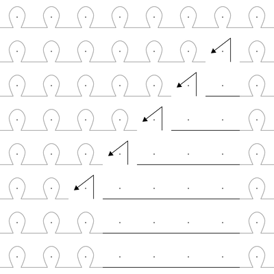
A shaper program describes a function which links stitch units between two consecutive course rows of sizes and . Since the order is not important as we are creating bidirectional wale connections, we assume that . The program takes as input , , as well as the current index within the first course (), and potentially other context parameters. Its output is a (possibly empty) sequence of mappings between cells of the first course and cells of the second course. For two courses of same sizes, the simplest mapping is . Two common shaping programs (uniform and center) are illustrated in Figure 24. Given the mapping from the shaping program, our system then creates corresponding wale connections between the associated stitch units.
In comparison, systems that build upon meshes such as AutoKnit [18] or Stitch Meshes [39, 37, 38] do not directly provide user control over increases and decreases. Instead, these are implicitly encoded in the original mesh. Figure 24 shows that we can use such programs to control the location of seams, which is of interest when customizing a garment.
13 Limitations of the Shaping Primitives
One constraint of wholegarment industrial knitting machines is that they cannot instantaneously introduce a new garment section (i.e. tubular or flat sheets) with a perpendicular wale flow. Instead, perpendicular wale flows must be joined in a continuous gluing operation that connects the two suspended sections laterally, as illustrated in Figure 25.
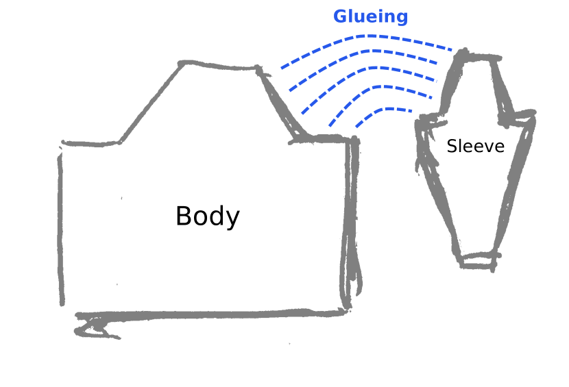
The current primitives of this work do not support such continuous gluing operation. This notably means that we cannot knit garments with sleeves extending perpendicularly to the base trunk. Note that it is quite different from our Joint primitive whose flow is continuously changed from its bottom to its top, because it does not split the flow, but only redirect it in a single direction.
Possible solutions we envision include:
-
•
Adding a specialized T-Junction primitive (although we are looking for a more general and simpler-to-specify primitive)
-
•
Introducing lateral interfaces for flat sheet primitives, which – combined with Joints and Split – would allow the creation of T-Junction structures (and more)
-
•
Introducing an Anchor primitive that would allow specifying regions on top of current other primitives, to specify additional interfaces (e.g. hole sections, from which we could generate new lateral primitives).
Any of these unfortunately comes with many complication in terms of implementation and layout optimization because we cannot work with full courses alone and must allow binding courses to parts of other courses over time (i.e. for the lateral gluing operation). There is also the problem of how the user would parameterize the gluing process as many variants exist [4].
14 Performance
The running time for our system is highly dependent on the client machine and web browser being used. However, we still provide performance tables here to highlight the current processing bottlenecks: (1) the stitch instantiation and (2) the pattern development.
| Skeleton | Shape | Pattern | Layout | Yarn | Update | Code | |||||||||||
|---|---|---|---|---|---|---|---|---|---|---|---|---|---|---|---|---|---|
| Name | Nodes | Patterns | Stitches | Create | Schedule | Trace | Develop | Create | Optimize | Pack | Interpret | Simulate | Compact | Shape | Pattern | Total | Generate |
| cat-32x32 | 1 | 2 | 1024 | 3 | 1 | 8 | 30 | 4 | 1 | 7 | 6 | 1 | 2 | 33 | 51 | 63 | 27 |
| cat-64x64 | 1 | 2 | 4096 | 8 | 1 | 15 | 21 | 3 | <1 | 18 | 14 | 1 | 5 | 65 | 62 | 86 | 40 |
| glove | 10 | 3 | 5030 | 12 | 1 | 11 | 27 | 6 | 9 | 36 | 24 | 9 | 8 | 116 | 119 | 143 | 46 |
| cat-128x128 | 1 | 2 | 16384 | 46 | <1 | 70 | 97 | 9 | 1 | 71 | 52 | 9 | 20 | 278 | 259 | 375 | 77 |
| sock | 6 | 1 | 17740 | 46 | <1 | 50 | 89 | 18 | <1 | 70 | 46 | 8 | 34 | 272 | 265 | 361 | 101 |
| corgy | 1 | 4 | 19200 | 22 | 1 | 78 | 129 | 13 | <1 | 83 | 60 | 11 | 24 | 292 | 320 | 421 | 76 |
| beanie | 3 | 1 | 28774 | 141 | <1 | 79 | 124 | 29 | 1 | 107 | 67 | 7 | 51 | 482 | 386 | 606 | 96 |
| noisy-scarf | 1 | 1 | 85000 | 199 | <1 | 328 | 1034 | 54 | <1 | 309 | 219 | 86 | 140 | 1335 | 1842 | 2369 | 335 |
For both issues, we refer to Table 2 where we provide timings for most of the shape skeletons within the paper, excluding rendering times. These are captured on 64-bit Ubuntu 16.04 with Intel® Core™ i7-3820 CPU @ 3.60GHz i7 (8 processors) and 24GB of RAM. The test browser was Chromium 74. To have a reasonable idea of the peak performance, we ran the profiling by loading the skeleton file, then switching to Compact mode, and generating the output times consecutively before actually measuring the times we report here. This warm-up leads the browser to optimize hot functions with its Just-In-Time compiler. We then export the machine code times before measuring the code generation time.
The compaction time isn’t actually needed except for shapes using branches (here mainly glove) but our implementation instantiates a new bed whether there is a need for it (branching) or not, so the total update times might be smaller in practice if the user does not toggle bed compaction.
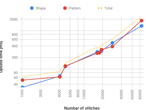
Generally, these timings are not meaningful as absolute numbers, but to understand the relative profile of different processes w.r.t. different shape complexities. Both shape and pattern updates have mostly linear runtimes as shown in Figure 26 for the considered shapes. However, the complexity of user patterns is of course going to be dependent on the user pattern. The linear behaviour for pattern development comes from the fact that filter operations traverse all stitches, and thus most of our operations end up being linear in that number.
14.1 Instantiating Stitches
In the current implementation, we generate the layout from scratch every time a change happens. This makes our implementation very simple, but prevents us from reusing most of the data that doesn’t change. Unfortunately, reusing stitch information is not easy because simple stitch modifications can have drastic impacts on the whole needle bed (e.g., adding a course at the beginning shifts all following stitches). For the shape part, our system runs mostly linearly in the number of stitches, and thus we are limited in the size of our garment shape.
When purely editing the pattern, we avoid recreating the whole data-structure since the pattern development does not remove or add stitches. Instead, we clear the stitch operations of all stitches, and re-apply the patterns, interpretation, simulation and compaction steps (since these are dependent on both the shape and the pattern).
14.2 Pattern Development
The pattern code evaluation is of course going to be longer to evaluate the more complex the pattern is. Our DSL implementation packs all stitches in a linear array and then mainly relies on filtering the set of indexed stitches for the queries, whereas the operations are done by traversing the current selected indices and applying the operation on the corresponding stitch objects. The implementation we provide performance for is purely CPU-based.
We expect possible improvements through a GPU implementation that would compile our DSL as shaders or other compute programs for GPGPU.
15 Additional Non-Expert Results
Figures 27 and 28 present additional results from the patterning task of our non-expert user sessions. Although neither of our users had previous experience with knitting, both were able to generate interesting, machine-knittable results within a few hours of their start with our system.
16 Making the Green Glove
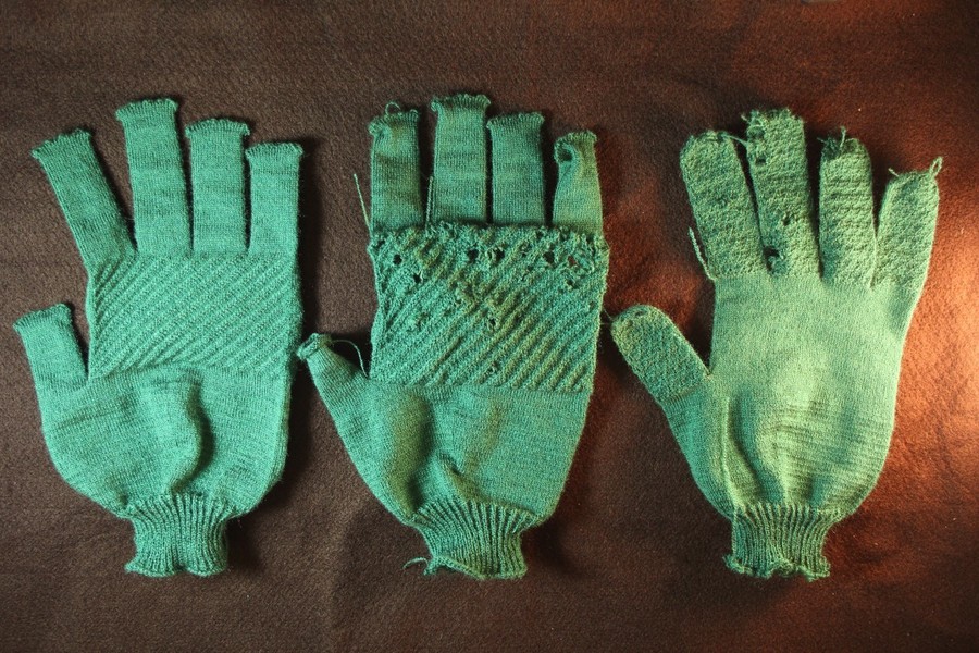
The green glove of the last Figure from the main paper went over a few complicated iterations whose main results are shown in Figure 29. The initial design was intending to add gripping texture under the fingers. It was going to do so with continuously shifted cross patterns. Furthermore, its finger ends were to be closed with some shaping at their ends.
The first issue arose from the finger ends that had used very quick increases, with unstable kickback operations next to future increases. This led to a few holes at the finger tips. This can be fixed by changing the shaping, but also shows that one would definitely benefit from being able to manually specify the expected shaping seams, since then one could route the yarn correctly and avoid unstable increases. We plan to automate the detection and fixing of such problems.
The more interesting issue came from the move patterns on the fingers. The basic glove skeleton we used was starting the knitting from the fingers to avoid having to split the fingers into multiple knitting sections. This would have been required if starting from the cuffs, because a large knitted section is eventually suspended (the palm), from which smaller branches extends, one-by-one. In that case, the tension at the boundary of the branches increases the farther the finger knitting is, which eventually leads to the yarn breaking.
Typically, this can easily be solved for gloves by starting the knitting from the fingers. However, one issue is then that the fingers are kept suspended until the palm can be knitted (i.e., all fingers have been knitted). Unfortunately, this means that patterning the individual fingers with patterns that include large movements leads to the suspended yarn being stretched continuously. This is possible, but ended up breaking the yarn in random locations with the tension we used.
Instead, our user decided to move the pattern to the main palm, which solved the issues with the fingers (after also improving the shape of finger tips to be stable). Unfortunately, knitting continuous cables over a large area requires a correct tension parameter. Our initial setup was incorrectly estimating that the required yarn tension should be very loose (because of the many cables), but effectively they all combined into small shifts, that do not stretch the yarn beyond 2 needle pitches globally. Having a wrongly loose tension typically leads to the yarn not catching correctly, and more unfortunately in it catching onto wrong needles on the sides. This leads to unpredictable behaviours and eventually led to fabric pile up (stopping the machine and also breaking a needle during the clearing process). Fixing the tension led to a completely fine glove.
This illustrates that although our system can allow users to create programs for shaping and patterning, there are still components missing to allow fully automated knitting as a service. We still require some expertise in how to handle the tension and other machine parameters, which brings up many interesting avenues for research.