Nagaoka ferromagnetism observed in a quantum dot plaquette
Engineered, highly-controllable quantum systems hold promise as simulators of emergent physics beyond the capabilities of classical computers Feynman1982 . An important problem in many-body physics is itinerant magnetism, which originates purely from long-range interactions of free electrons and whose existence in real systems has been subject to debate for decades Auerbach1994 ; Mattis2006 . Here we use a quantum simulator consisting of a four-site square plaquette of quantum dots Mukhopadhyay2018 to demonstrate Nagaoka ferromagnetism Nagaoka1966 . This form of itinerant magnetism has been rigorously studied theoretically Mattis2003 ; Nielsen2007 ; Oguri2007 ; Stecher2010 but has remained unattainable in experiment. We load the plaquette with three electrons and demonstrate the predicted emergence of spontaneous ferromagnetic correlations through pairwise measurements of spin. We find the ferromagnetic ground state is remarkably robust to engineered disorder in the on-site potentials and can induce a transition to the low-spin state by changing the plaquette topology to an open chain. This demonstration of Nagaoka ferromagnetism highlights that quantum simulators can be used to study physical phenomena that have not yet been observed in any system before. The work also constitutes an important step towards large-scale quantum dot simulators of correlated electron systems.
The potential impact of discovering and understanding exotic forms of magnetism and superconductivity is one of the largest motivations for research in condensed-matter physics. These quantum mechanically governed effects result from the strong correlations that arise between interacting electrons. Modelling and simulating such systems can in some instances only be achieved through the use of engineered, controllable systems that operate in the quantum regime Feynman1982 . Efforts to build quantum simulators have already demonstrated great promise at this early stage Georgescu2014 , mainly led by the ultracold atom community Trotzky2008 ; Nascimbene2012 ; Bloch2012 ; Dai2017 ; Goerg2018 ; Salomon2018 ; Nichols2018 . More broadly, quantum simulations of many-body fermionic systems have been carried out in a range of experimental systems such as quantum dot lattices Singha2011 , dopant atoms Salfi2016 , superconducting circuits Barends2015 and trapped ions Martinez2016 .
Electrostatically defined semiconductor quantum dots Kouwenhoven2001 ; Wiel2002 ; Hanson2007 have been proposed as excellent candidates for quantum simulations Manousakis2002 ; Byrnes2008 ; Barthelemy2013 . Their ability to reach thermal energies far below the hopping and on-site interaction energies enable access to previously unexplored material phases. Quantum dot systems have already achieved success in realising simulations of Mott-insulator physics in linear arrays Hensgens2017 . Additionally, the feasibility to extend these systems into 2D lattices has recently been demonstrated Thalineau2012 ; Seo2013 ; Noiri2017 ; Mukhopadhyay2018 ; Mortemousque2018 , including the ability to perform measurements of spin correlations Mukhopadhyay2018 . As a result, quantum dot systems are now prime candidates for exploring how superconductivity and magnetism emerge in strongly-correlated electron systems Scalapino1995 ; Tsuei2000 ; Balents2010 .
The emergence of magnetism in purely itinerant electron systems presents a long-standing problem in quantum many-body physics Auerbach1994 ; Mattis2006 with only few rigorous theoretical results, for instance in systems with special flat bands or Nagaoka’s ferromagnetism (see Ref. Tasaki1998 and references therein). The Nagaoka model of ferromagnetism Thouless1965 ; Nagaoka1966 relies on the simplicity of the Hubbard model Hubbard1963 , which captures complex correlations between electrons in a lattice with only two Hamiltonian parameters. Using this single-band model, Nagaoka proved analytically that for some lattice configurations, and in the limit of infinitely strong interactions, the presence of a single hole on top of a Mott-insulating state with one electron per site renders the ground state ferromagnetic. The Nagaoka mechanism can be intuitively understood as an interference effect between the different paths that the hole can take across the lattice. These paths interfere constructively when all lattice sites have the same spin orientation, which lowers the kinetic energy of the hole.
Given that Nagaoka obtained his rigorous result using unrealistic limits, it has been an open question whether this mechanism can still be responsible for the observation of ferromagnetism in an experimental, finite-size system, in the presence of long-range interactions and disorder, as well as additional available orbitals. In this light, we note that a ferromagnetic state is a fully-polarised spin state, and as such is an eigenstate of the total spin operator . This statement is true whether the system is in the thermodynamic limit, or whether it is finite size. The feasibility of performing a quantum simulation of Nagaoka ferromagnetism has been explored theoretically for quantum dots Mattis2003 ; Nielsen2007 ; Oguri2007 as well as optical superlattices Stecher2010 , but there are no experimental reports to date.
In this article, we present clear experimental evidence of Nagaoka ferromagnetism, using a quantum dot device designed to host a 22 array of electrons. Using the high degree of parameter tunability, we study how external magnetic fields and disorder in local potentials affect the magnetic nature of the ground state. Furthermore, by effectively tuning the geometry of the system from periodic to open boundary conditions, we experimentally demonstrate the suppression of ferromagnetism expected from the Lieb-Mattis theorem Lieb1962 .
Nagaoka in the quantum dot plaquette
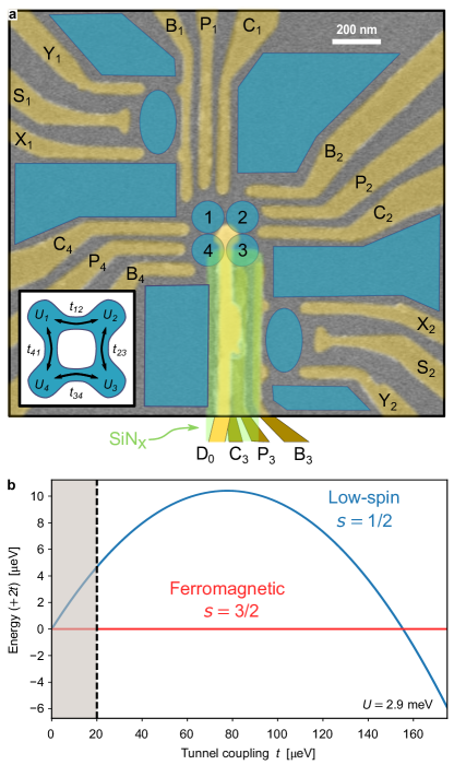
The single-band Hubbard model provides a simple description of interacting electrons in a lattice, such as the plaquette of electrostatically defined and controlled quantum dots (Fig. 1a). The Hamiltonian contains competing kinetic energy and electron-electron interaction terms:
| (1) |
where describes electron tunnelling between sites and , is the on-site Coulomb repulsion energy at site and is a local energy offset at site . In typical quantum dot systems, is mainly set by the geometry of the device and is on the order of meV, while and can be controlled by gate voltages in the range of to meV and to meV respectively Barthelemy2013 . The operators , and represent the second quantisation annihilation, creation and number operators for an electron on site with spin projection .
Nagaoka ferromagnetism is predicted to occur with an almost-half-filled lattice, which for the case of the 22 plaquette corresponds to having three interacting electrons in the four-site system. By additionally restricting the system to nearest-neighbour-only coupling, the Hamiltonian is analytically solvable Mattis2003 for homogeneous interactions (, , ) and in the limit , where the lowest eigenenergies are:
| (2) |
Here, is the energy of the high-spin, ferromagnetic quadruplets (with total spin ) and is the energy of the 2 sets of low-spin degenerate doublets (see supplementary material for details).
We note that the Hamiltonian in Eq. 1 neglects some of the essential features of the experimental device used in this work. For comparison with experimental results, we employ a more general model Hamiltonian, in which we account for interdot Coulomb repulsion (in Fig. 2a), spin-orbit and hyperfine interactions (in Fig. S4a), as well as the effects of external magnetic fields (in Fig. 5a-b). The implementation of these terms is described in detail in the supplementary material. In addition to this model, we have also performed an ab initio calculation (see supplementary material and Ref. Wang2019 ) based on multiple orbitals solved from a potential landscape with 22 minima, showing very similar results to those obtained with Eq. 1.
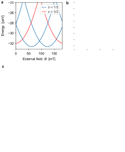
The simple model described by Eqs. 1 and 2 already provides some useful insight into the parameter regimes relevant to the experiment. The ferromagnetic state is the ground state at large , with a transition to a low-spin ground state occurring at . The quantum dot array used in this work has an average meV, with tunable nearest-neighbour tunnel couplings in the range of eV Mukhopadhyay2018 . Unless otherwise stated, we set eV. This means that we are probing the regime where the ground state is expected to be ferromagnetic (see Fig. 1b).
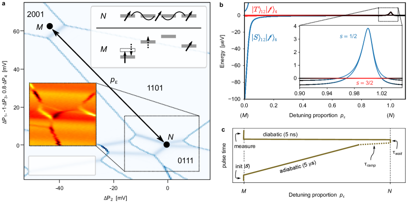
We prepare the system by using charge stability diagrams Wiel2006 to find the appropriate voltage bias that will stabilise the system in a charge configuration with 3 resonant electrons delocalised in the 4 sites. We set the local energy reference at this regime as eV for all dots, and refer to this condition as point . Charge stability diagrams are also used to tune the gates to the measurement point , where single-shot measurements in the singlet-triplet basis are performed on 2 of the 3 electrons. Fig. 2a and Fig. S1 show simulated and measured charge stability diagrams where points and can be identified, along with an inset schematic of the dot local energies at these points.
With the accessible system parameters, the theoretically expected (Fig. 1b) energy gap between the ferromagnetic () and low-spin () states at point is eV, comparable to the measured electron temperature eV ( mK) Mukhopadhyay2018 . In order to study the magnetic properties of the ground state, we have developed a technique (see Fig. 2b-c) based on initialising a low-entropy state at point and adiabatically pulsing to point to access the ground state. We then diabatically pulse back to point and probe the spin state of the system on timescales faster than the relaxation times. By shortening the ramp time of the pulse from point to we can also access excited states. To distinguish whether the system is in a ferromagnetic or low-spin state, we repeat the cycle of preparation and measurement, and extract the triplet probability , which informs us on the nature of the original 3-spin state (see supplementary material for details). In the Methods section we provide a detailed description of these preparation and measurement protocols.
Experimental results
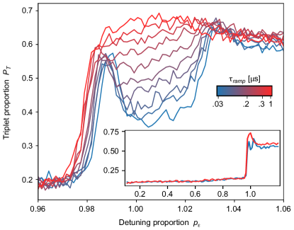
Fig. 3 shows plots of as we perform measurements at different values of detuning proportion , defined as the quantity that sets the linear combination of gate voltages (see Fig. 1a) such that at the system is tuned to point (). From the inset of the figure we highlight that remains at a low value for most of the range, with a sharp increase as approaches 1 (point ). This is consistent with the expectation that the electrons will remain localised until the region close to point , where they begin to delocalise and the measurement starts to project the three interacting spins (see Methods for details). This is expected to happen after , where the energy spectrum (see inset of Fig. 2b) shows an energy level crossing and the states become the ground state. The non-zero triplet fraction at low is attributed partly to thermal excitations during the initialisation stage (see Methods)–as a consequence of the finite electron temperature–and partly to a small probability of leakage to excited states during the pulse.
The main plot shows the measurement around point , for a range of . In the region , a clear increase of is observed as is increased, consistent with a gradual transition from diabatically pulsing into the low-spin state, to adiabatically pulsing into the ferromagnetic state, where is maximum. For the faster pulses, we see ‘peaks’ of at and , where the pulse reaches the energy-level crossings, as all the spin states quickly (i.e., much faster than the experimental timescales) mix due to the nuclear hyperfine fields and spin-orbit coupling Khaetskii2002 ; Merkulov2002 ; Chekhovich2013 .
The timescale for the diabatic to adiabatic transition shown in Fig. S3a can be theoretically studied using time-evolution simulations with an extended-Hubbard model (see supplementary material for details). From fits to the data we estimate a hyperfine coupling parameter neV, in agreement with previous observations and calculations in similar GaAs quantum dot systems Petta2005 ; Koppens2005 ; Chekhovich2013 . Fig. S3b shows as a function of the waiting time spent at point (), consistent with thermal equilibration of the system with a timescale s.
We note that we cannot directly assign the measured values of to and populations, because the observed is subject to measurement imperfections caused by mechanisms that are difficult to disentangle, such as the finite measurement bandwidth, the signal-to-noise ratio and to relaxation, as well as unwanted leakage to other states during the pulsed passages.
Changing topology – from 2D to 1D
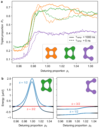
Whereas the square plaquette can be thought of as a 1D ring, the Lieb-Mattis theorem Lieb1962 ; Mattis2003 asserts that the ground state of a 1D array of electrons with open boundary conditions has the lowest possible spin. We can intuitively understand the difference between these two configurations when we consider how the hole tunnels to its next-nearest neighbour Mattis2006 . In a 2D plaquette, the hole has 2 possible paths to the next-nearest neighbour. If the system is initialised in any of the configurations, the 2 paths will leave the system in 2 different spin configurations. On the other hand, for an system the 2 paths leave identical spin configurations, and interfere constructively to lower the kinetic energy. In contrast, in an open boundary 1D array, the kinetic energy of the hole is independent of the spin configurations of the neighbouring electrons as there is only one path for the hole through the array.
One powerful feature of the quantum dot system is that the tunnel barriers can be tuned independently, allowing us to test different array topologies. In Fig. 4a we compare diabatic and adiabatic sweeps as we raise the tunnel barrier that controls , effectively transforming the plaquette into a system that behaves more like an open-boundary 1D system. In the latter regime, we see that becomes insensitive to sweep rate. Additionally, we no longer observe the peaks of for the fast sweep rate, which we had associated with mixing at the avoided level crossings. From these observations we infer that for the open chain, the instantaneous ground state does not exhibit an avoided crossing between an state and an state as the system is taken to point . In this regime the sweeps will always evolve to the ground state, independent of the sweep rate. This interpretation is also consistent with the numerical simulations of the energy spectrum shown in Fig. 4b.
Effects of external magnetic fields
Given that Nagaoka ferromagnetism originates from interference effects due to the trajectories of the hole around the ring, it then follows that a magnetic flux through the plaquette will add an Aharonov-Bohm phase Aharonov1959 that disturbs the interference effects. We capture this effect in the theoretical model by adding a magnetic field dependent gauge to the tunneling term in Eq. 1. In addition, the application of an external field subjects the system to the Zeeman effect, causing a spin-dependent energy offset. See supplementary material for details on how the gauge and Zeeman terms are implemented in the extended-Hubbard model.
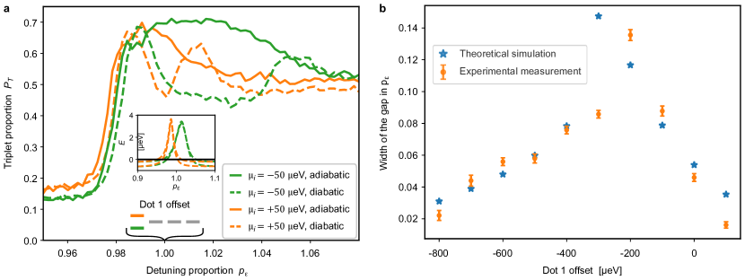
Fig. 5a shows the effect of a magnetic field through the plaquette on the spectrum, ignoring the Zeeman effect. The lowest and levels at point are shown as a function of the applied field, where periodic crossings can be observed. In the range mT, the system ground state transitions to the low-spin state, with the perhaps counterintuitive implication that we can destroy the ferromagnetic state by applying a magnetic field. Additionally, this effect highlights that the ferromagnetic state in this system is dominated by the Nagaoka effect rather than long-range interactions. In line with this observation, the ab initio calculations suggest that long-range interactions only account for of the ferromagnetic polarisation Wang2019 . When we include the Zeeman effect (see Fig. 5b) the picture becomes more complicated, because both Zeeman and orbital effects cause perturbations of similar energy scales.
From this initial numerical analysis, it is clear that the experimental characterisation of the effect of the external field will be challenging, due to the increased complexity of the spectral structure of the spin states as a function of field. The small energy splittings that appear both at point , as well as at lower values (see inset of Fig. 5c) are expected to cause mixing of the spin states during the adiabatic pulses. To minimise this mixing, we adjusted the pulsing protocol such that we pulse adiabatically ( s ramp) to , then pulse diabatically ( ns ramp) the rest of the way. The results in Fig. 5c show that from to mT increases at point , and we stop observing the characteristic dip. Note that the range of field that we were able to probe is still below the estimated ground state transition point ( mT). Therefore, we infer that the observed increase in results from hybridisation of the and states as their energy gap reduces. We cannot claim that the observed hybridisation of states is occurring solely at point , as it is evident from the increase in at (i.e. prior to the energy-level crossings) that some of the mixing is occurring during the pulse. However, we do see that in all plots converge at the energy-level crossings ( and ) suggesting that the Aharonov-Bohm orbital effects are partly responsible for the additional mixing near point . Attempts to perform the measurement at higher fields closer to the expected spin-state transition resulted in similar plots.
Sensitivity to local energy offsets
We also use the tunability available in quantum dot systems to study the effects of disorder of the local potential. For the plot in Fig. 6a, we modified the experimental protocol used to probe the states at point , pulsing instead to a point , where the local energy of dot 1 is offset by eV. We achieve this by employing the virtual gates technique Hensgens2017 ; Mukhopadhyay2018 , which gives access to control knobs that map a linear combination of gates onto local dot energy offsets. The measurements show that the region in the detuning trajectory where the ferromagnetic state is the ground state changes in width and position when different offsets are applied. The panel inset shows the expected energy spectra when we simulate the experimental conditions using the model in Eq. 1. The spectra show excellent qualitative agreement to the measured variations in width and position of the gapped region. In Fig. S7 we repeated the measurement on each of the four dots, showing similar qualitative agreement with theory.
Fig. 6b compares experimental measurements and theoretical predictions of the width of the detuning proportion region (as defined in the caption of Fig. S8) with a ferromagnetic ground state energy gap, for offsets of dot 1 in the range to eV. This plot further confirms the interpretation of the experimental observations, showing excellent agreement between measurements and theoretical predictions. Remarkably, the system still shows signs of the ferromagnetic ground state with offsets up to eV (see Fig. S8), more than an order of magnitude larger than the tunnel coupling. We also note that the theoretical simulations in Fig. S8 suggest that from eV the ground state is no longer , even though the measurement still shows a gap in between diabatic and adiabatic sweeps. The presence of this gap is explained by the large splitting between the two branches that occurs at such large local offsets.
Discussion
In this work we have presented the first measurements showing experimental evidence of Nagaoka’s 50-year old theory in a small-scale system. The large degree of tunability, high ratio of interaction strength to temperature, and fast measurement techniques available to quantum dot systems, allowed observing both the ferromagnetic ground state and the low-spin excited state of an almost-half-filled lattice of electrons. By performing a quantum simulation involving both charge and spin, it builds on previous demonstrations Hensgens2017 that quantum dot systems can be useful simulators of the extended Hubbard model, despite their initial inhomogeneities in the potential shape and local energies. Furthermore, in this work we showed a flavour of the capabilities for studying the sensitivity to disorder, and these experiments already revealed some remarkable effects, when we found that the Nagaoka condition can still be observed after offsetting a local energy by amounts much larger than the tunnel coupling. This can readily be studied in further detail, along with other possibilities for exploring the effects of disorder, which could bring insights into e.g., the stability of the ferromagnetic state. More quantitative insight of the energy gap between the spin states can be achieved through spectroscopy measurements, using techniques such as applying oscillating electric fields through a gate Nowack2007 or observing ‘exchange-like’ oscillations Malinowski2018 .
While the problem of three electrons in a four-site plaquette can be solved analytically using the single-band Hubbard picture, a complete description of this experimental system that includes all its available orbitals is not easily tractable, analytically or numerically. Indeed, the computational cost of the ab initio calculation of the 5 lowest states, with long-range and on-site interaction terms being considered, is on the order of CPU hours. Small-scale simulations on tractable models can be used to systematically benchmark the performance of devices as the scale-up technology develops towards devices that can perform classically intractable simulations. Larger quantum dot systems (or other experimentally controllable systems), such as 2N or MN arrays can shed more light on the existence of purely itinerant ferromagnetism in real systems. The exchange interaction grows proportionally to the system size, creating a competition against the hopping energy that is characteristic of Nagaoka ferromagnetism, and leaving the fate of the Nagaoka mechanism in larger systems unknown.
References
- (1) Feynman, R. P. Simulating physics with computers. Int. J. Theor. Phys 21, 467–488 (1982).
- (2) Auerbach, A. Interacting Electrons and Quantum Magnetism (Springer New York, 1994).
- (3) Mattis, D. C. The Theory of Magnetism Made Simple (World Scientific, 2006).
- (4) Mukhopadhyay, U., Dehollain, J. P., Reichl, C., Wegscheider, W. & Vandersypen, L. M. K. A 2x2 quantum dot array with controllable inter-dot tunnel couplings. Appl. Phys. Lett. 112, 183505 (2018).
- (5) Nagaoka, Y. Ferromagnetism in a narrow, almost half-filled s band. Phys. Rev. 147, 392–405 (1966).
- (6) Mattis, D. C. Eigenvalues and magnetism of electrons on an artificial molecule. Int. J. Nanosci. 02, 165–170 (2003).
- (7) Nielsen, E. & Bhatt, R. N. Nanoscale ferromagnetism in nonmagnetic doped semiconductors. Phys. Rev. B 76, 161202(R) (2007).
- (8) Oguri, A., Nisikawa, Y., Tanaka, Y. & Numata, T. Kondo screening of a high-spin Nagaoka state in a triangular quantum dot. J. Magn. Magn. Mater. 310, 1139–1141 (2007).
- (9) von Stecher, J., Demler, E., Lukin, M. D. & Rey, A. M. Probing interaction-induced ferromagnetism in optical superlattices. New J. Phys. 12, 055009 (2010).
- (10) Georgescu, I. M., Ashhab, S. & Nori, F. Quantum simulation. Rev. Mod. Phys. 86, 153–185 (2014).
- (11) Trotzky, S. et al. Time-resolved observation and control of superexchange interactions with ultracold atoms in optical lattices. Science 319, 295–299 (2008).
- (12) Nascimbène, S. et al. Experimental realization of plaquette resonating valence-bond states with ultracold atoms in optical superlattices. Phys. Rev. Lett. 108, 205301 (2012).
- (13) Bloch, I., Dalibard, J. & Nascimbène, S. Quantum simulations with ultracold quantum gases. Nat. Phys. 8, 267–276 (2012).
- (14) Dai, H.-N. et al. Four-body ring-exchange interactions and anyonic statistics within a minimal toric-code Hamiltonian. Nat. Phys. 13, 1195–1200 (2017).
- (15) Görg, F. et al. Enhancement and sign change of magnetic correlations in a driven quantum many-body system. Nature 553, 481–485 (2018).
- (16) Salomon, G. et al. Direct observation of incommensurate magnetism in Hubbard chains. Nature 565, 56–60 (2018).
- (17) Nichols, M. A. et al. Spin transport in a Mott insulator of ultracold fermions. Science 363, 383–387 (2018).
- (18) Singha, A. et al. Two-dimensional Mott-Hubbard electrons in an artificial honeycomb lattice. Science 332, 1176–1179 (2011).
- (19) Salfi, J. et al. Quantum simulation of the Hubbard model with dopant atoms in silicon. Nat. Commun. 7, 11342 (2016).
- (20) Barends, R. et al. Digital quantum simulation of fermionic models with a superconducting circuit. Nat. Commun. 6, 7654 (2015).
- (21) Martinez, E. A. et al. Real-time dynamics of lattice gauge theories with a few-qubit quantum computer. Nature 534, 516–519 (2016).
- (22) Kouwenhoven, L. P., Austing, D. G. & Tarucha, S. Few-electron quantum dots. Rep. Prog. Phys. 64, 701–736 (2001).
- (23) van der Wiel, W. G. et al. Electron transport through double quantum dots. Rev. Mod. Phys. 75, 1–22 (2002).
- (24) Hanson, R., Kouwenhoven, L. P., Petta, J. R., Tarucha, S. & Vandersypen, L. M. K. Spins in few-electron quantum dots. Rev. Mod. Phys. 79, 1217–1265 (2007).
- (25) Manousakis, E. A quantum-dot array as model for copper-oxide superconductors: A dedicated quantum simulator for the many-fermion problem. J. Low Temp. Phys. 126, 1501–1513 (2002).
- (26) Byrnes, T., Kim, N. Y., Kusudo, K. & Yamamoto, Y. Quantum simulation of Fermi-Hubbard models in semiconductor quantum-dot arrays. Phys. Rev. B 78, 075320 (2008).
- (27) Barthelemy, P. & Vandersypen, L. M. K. Quantum dot systems: a versatile platform for quantum simulations. Ann. Phys. (Leipzig) 525, 808–826 (2013).
- (28) Hensgens, T. et al. Quantum simulation of a Fermi–Hubbard model using a semiconductor quantum dot array. Nature 548, 70–73 (2017). eprint 1702.07511v1.
- (29) Thalineau, R. et al. A few-electron quadruple quantum dot in a closed loop. Appl. Phys. Lett. 101, 103102 (2012).
- (30) Seo, M. et al. Charge frustration in a triangular triple quantum dot. Phys. Rev. Lett. 110 (2013).
- (31) Noiri, A. et al. A triangular triple quantum dot with tunable tunnel couplings. Semicond. Sci. Technol. 32, 084004 (2017).
- (32) Mortemousque, P.-A. et al. Coherent control of individual electron spins in a two dimensional array of quantum dots. http://arxiv.org/abs/1808.06180v1 (2018). eprint http://arxiv.org/abs/1808.06180v1.
- (33) Scalapino, D. J. The case for dx2 - y2 pairing in the cuprate superconductors. Phys. Rev. 250, 329–365 (1995).
- (34) Tsuei, C. C. & Kirtley, J. R. Pairing symmetry in cuprate superconductors. Rev. Mod. Phys. 72, 969–1016 (2000).
- (35) Balents, L. Spin liquids in frustrated magnets. Nature 464, 199–208 (2010).
- (36) Tasaki, H. From Nagaoka’s ferromagnetism to flat-band ferromagnetism and beyond: An introduction to ferromagnetism in the Hubbard model. Progress of Theoretical Physics 99, 489–548 (1998).
- (37) Thouless, D. J. Exchange in solid 3He and the Heisenberg Hamiltonian. Planet. Space Sci. 86, 893–904 (1965).
- (38) Hubbard, J. Electron correlations in narrow energy bands. P. Roy. Soc. Lon. A 276, 238–257 (1963).
- (39) Lieb, E. & Mattis, D. Theory of ferromagnetism and the ordering of electronic energy levels. Phys. Rev. 125, 164–172 (1962).
- (40) Wang, Y. et al. Ab initio exact diagonalization simulation of the Nagaoka transition in quantum dots. Phys. Rev. B 100, 155133 (2019).
- (41) van der Wiel, W. G., Stopa, M., Kodera, T., Hatano, T. & Tarucha, S. Semiconductor quantum dots for electron spin qubits. New J. Phys. 8, 28 (2006).
- (42) Khaetskii, A. V., Loss, D. & Glazman, L. Electron spin decoherence in quantum dots due to interaction with nuclei. Phys. Rev. Lett. 88, 186802 (2002).
- (43) Merkulov, I. A., Efros, A. L. & Rosen, M. Electron spin relaxation by nuclei in semiconductor quantum dots. Phys. Rev. B 65, 205309 (2002).
- (44) Chekhovich, E. A. et al. Nuclear spin effects in semiconductor quantum dots. Nat. Mater. 12, 494–504 (2013).
- (45) Petta, J. R. Coherent Manipulation of Coupled Electron Spins in Semiconductor Quantum Dots. Science 309, 2180–2184 (2005).
- (46) Koppens, F. H. L. Control and Detection of Singlet-Triplet Mixing in a Random Nuclear Field. Science 309, 1346–1350 (2005).
- (47) Aharonov, Y. & Bohm, D. Significance of electromagnetic potentials in the quantum theory. Phys. Rev. 115, 485–491 (1959).
- (48) Nowack, K. C., Koppens, F. H. L., Nazarov, Y. V. & Vandersypen, L. M. K. Coherent Control of a Single Electron Spin with Electric Fields. Science 318, 1430–1433 (2007).
- (49) Malinowski, F. K. et al. Spin of a multielectron quantum dot and its interaction with a neighboring electron. Phys. Rev. X 8, 011045 (2018).
Acknowledgements
We acknowledge input and discussions with M. Chan, S. Philips, Y. Nazarov, F. Liu, L. Janssen, T. Hensgens, T. Fujita and all of the Vandersypen team, as well as experimental support by L. Blom, C. van Diepen, P. Eendebak, R. Schouten, R. Vermeulen, R. van Ooijik, H. van der Does, M. Ammerlaan, J. Haanstra, S. Visser and R. Roeleveld. L.M.K.V. thanks the NSF-funded MIT-Harvard Center for Ultracold Atoms for its hospitality. This work was supported by grants from the Netherlands Organisation for Scientific Research (FOM projectruimte and NWO Vici) (J.P.D., U.M., L.M.K.V.), the European Research Council (ERC-Synergy) (V.P.M., L.M.K.V.), the Postdoctoral Fellowship in Quantum Science of the Harvard-MPQ Center for Quantum Optics and AFOSR-MURI Quantum Phases of Matter (Grant No. FA9550-14-1-0035) (Y.W.), the Swiss National Science Foundation (C.R., W.W.), The Villum Foundation (M.S.R.).
Data and code availability. Datasets obtained from the measurements described in this work, as well as code to plot the datasets and implement models used to reproduce all the figure in the main manuscript are available in the repository Zenodo with the identifier 10.5281/zenodo.3258940.