Particle dynamics in deposition of porous films with a pulsed radio-frequency atmospheric pressure glow discharge
Abstract
Nanoparticles grown in a plasma are used to visualize the process of film deposition in a pulsed radio-frequency (rf) atmospheric pressure glow discharge. Modulating the plasma makes it possible to successfully prepare porous TiO2 films. We study the trapping of the particles in the sheath during the plasma-on phase and compare it with numerical simulations. During the plasma-off phase, the particles are driven to the substrate by the electric field generated by residual ions, leading to the formation of porous TiO2 film. Using video microscopy, the collective dynamics of particles in the whole process is revealed at the most fundamental “kinetic” level.
Porous films deposited on substances have many applications such as perovskite-sensitized Burschka et al. (2013) and dye-sensitized Chen et al. (2009) solar cells, Li-ion batteries Qin et al. (2018), sensing Kimura et al. (2012); Liu et al. (2013), and photocatalysis Varshney et al. (2016). The recent development of atmospheric pressure glow discharges (APGD) makes the process of plasma assisted film deposition easier than traditional methods Chen et al. (2009); Justicia et al. (2002) since it can be performed in an open system with high growth rates at low thermal budgets Boysen et al. (2018); Massines et al. (2012); Shi and Kong (2006). However, the films deposited by plasma enhanced chemical vapor deposition (PECVD) are usually dense Hodgkinson and Sheel (2013); Li et al. (2019); Baba et al. (2017). It is challenging to deposit mesoporous films with particles in plasmas on the substrate since the particles are charged by the electron and ion currents and confined by the plasma potential Selwyn et al. (1989); Selwyn. et al. (1990), preventing them from being deposited Bazinette et al. (2016).
The dynamics of mesoscopic particles in plasmas has been widely studied in dusty plasma research Fortov et al. (2005); Shukla and Mamun (2002); Bouchoule (1999). Using video microscopy, the particle motion can be easily recorded in real time. In a low pressure plasma, the dynamics of a strongly coupled dusty plasma are virtually undamped Morfill and Ivlev (2009); Chaudhuri et al. (2011); Kryuchkov et al. (2018a). This makes dusty plasmas an ideal model system to study regular liquids and solids at the kinetic level Thomas and Morfill (1996); Rubin-Zuzic et al. (2006); Tsai et al. (2016); Wong et al. (2018); Kryuchkov et al. (2018b). However, in atmospheric plasmas, the collective dynamics of charged particles is fully damped, and has been barely studied.
In this work we use nanoparticles grown in a plasma to visualize the process of film deposition and demonstrate that modulating the plasma makes it possible to successfully prepare porous TiO2 films. The collective dynamics of the particles driven by the electric field in the initial stage of the plasma-off phase is revealed using video microscopy. We show that varying the plasma-off time allows to control the size of the deposited particles.
The experiments were conducted in a radio-frequency (13.56 MHz) dielectric barrier discharge system at atmospheric pressure, as shown in Fig. 1(a). A plasma was ignited in a capacitively coupled quartz discharge chamber. The discharge gap was mm high and mm wide. Two fluorine-doped tin oxide glass plates were used as electrodes, where the upper one was driven and the lower one was grounded. The particles were illuminated by a laser with wavelength of nm Thomas (1999); Thomas et al. (2004); Schlebrowski et al. (2013); Barbosa et al. (2015); Du et al. (2017). Two CMOS cameras were used to record the particle dynamics and the evolution of the discharge glow with a frame rate of frames per second (fps). Helium was used as discharge carrier gas for TiCl4 and H2O, and O2 was used as the oxidizing agent. The corresponding gas flow rates were set at , , and sccm, respectively.
The deposition of a porous film was achieved by pulse modulating the rf discharge. After igniting the helium plasma, we inlet carrier gases into the discharge chamber. The input voltage was set to V. Since the plasma conditions play an important role in the particle formation, we kept the plasma-on time ms, and varied the time of the plasma-off phase for , , , , ms, corresponding to the repetition frequencies , , , , and Hz. The particles grew in the plasma.
To characterize the TiO2 particles formed in the plasma, we collected the dust particles at the gas exit of the discharge chamber and performed transmission electron microscope (TEM) analysis to determine their sizes and structure. As shown in Fig. 1(b), the particles have a spherical shape. In the Selected Area Electron Diffraction (SAED) pattern in Fig. 1(c), the polymorphic rings indicate that the TiO2 particles are polycrystalline. The distribution of particle diameters was measured from the TEM images and shown in Fig. 1(d). The average diameter of the collected particles is nm. Larger particles can be formed in the plasma discharge but their amount is rather limited.
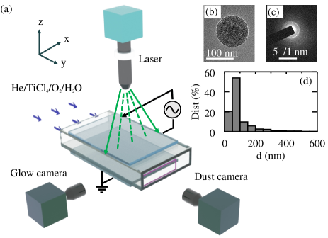
The polycrystalline TiO2 particles are formed in the He/TiCl4/O2/H2O atmospheric pressure plasma. The precursor molecules are excited/dissociated/ionized into active precursor species by the plasma first. Then they react and nucleate into nanoscale particles, agglomerate and further grow into submicron particles as displayed in Fig. 1 Bouchoule (1999); Mitic et al. (2018); Mikikian et al. (2016); Berndt et al. (2009); Couëdel et al. (2010). This process is accompanied by the formation of negatively charged clusters and the agglomeration of these clusters when critical densities are reached; further growth by radical sticking is halted when charging effects prevent further agglomeration. In our experiment with the continuous discharge, no TiO2 film can be deposited inside the discharge zone. This means that negatively charged TiO2 particles are formed as the precursor molecules enter the plasma discharge zone and become trapped near the sheath. The film deposition marginally depends on the diffusion and surface reaction of active species, but is achieved with a different process.
During the plasma-on phase of the modulated discharge, the negatively charged particles close to the axis of symmetry [dashed-dotted line in Fig. 2(a)] are confined in two layers close to the bottom and top electrodes with a huge void in-between Mikikian et al. (2010), as shown in Fig. 2(a). The ion drag force Khrapak et al. (2002) is balanced by the electric force in the (pre)sheath, and gravity plays a minor role. Close to the side of the chamber, vortexes are clearly visible, presumably caused by the thermophoretic force and neutral drag Schwabe et al. (2014); Rubin-Zuzic et al. (2007). Between the central stable region and the vortexes, there appear bent layers of particles at the position mm. The detailed origin of theses vortexes and bent layers is beyond the scope of this manuscript and will be described elsewhere. In this paper, we focus on the dynamics of particles in the region of interest (ROI) close to the chamber center, marked by a white rectangle in Fig. 2(a).
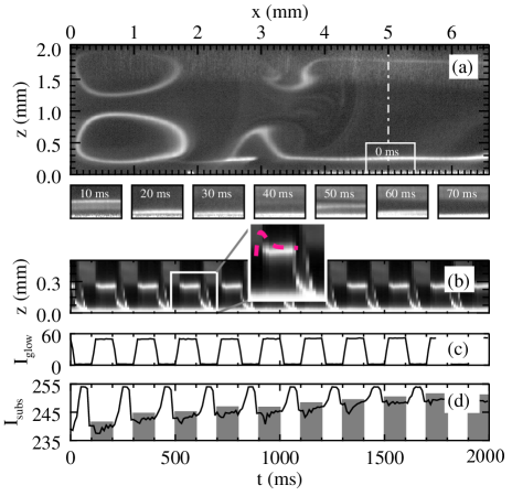
As the plasma-off phase starts, the glow disappears instantaneously in terms of the recording rate, as shown in Fig. 2(c). The particles can no longer be confined in the (pre)sheath. We show the particle positions in the ROI in consecutive frames recorded by the “dust camera” with a time interval of ms in Fig. 2(a). As we can see, the cloud drops to the bottom electrode within ms followed by a second drop at ms. This dynamics can also be clearly seen in the spatiotemporal evolution in Fig. 2(b). Particularly, the particle layer splits into two layers (at ms) as it falls down. The process of the (visible) particle deposition lasts for ms. After ms, the plasma is again ignited. The intensity of the glow, recorded by the “glow camera”, restores to a value of . The particles are trapped in the (pre)sheath again. However, the height of the particle layer shows a spike as soon as the plasma is ignited, and it restores to its equilibrium position afterwards. It is well known that dust particles can be used as diagnostics for the sheath Annaratone et al. (2004, 2003); Kersten et al. (2003); Basner et al. (2009). This result implies that a wider sheath is formed at the moment of ignition.
We performed a dedicated numerical simulation to study the evolution of the plasma sheath as the voltage is applied. The model simulates an atmospheric pressure, rf-driven capacitive discharge using a hybrid analytical-numerical global model. The model’s detailed description is given in the supplemental material as well as in Ref. Ding et al. (2014a, b); Lazzaroni et al. (2012). In the simulation, the sheath width increases to mm after the ignition of plasma. It decreases to a stable value of mm afterwards, as shown by a pink-dashed curve in the inset of Fig. 2(b). The spike of the height of the particle layer observed in the experiment is much smaller than the spike of the sheath width in the simulation. This is caused by the friction of particles in the atmospheric plasma, where the damping rate is about s-1. The particles cannot follow the formation of the sheath. Nevertheless, the experimental results show a qualitative agreement with the numerical simulation.
The particle acceleration towards the electrode in the plasma-off phase can be explained as follows. When the plasma is on, the particles are charged negatively due to the high electron thermal velocity. The estimated average particle charge number is Khrapak et al. (2006); Khrapak and Morfill (2009). After the plasma is off, the electron population is expected to vanish on a time scale of s, while the ion density remains almost unchanged. The charge is now determined by the balance of positive and negative ion fluxes. Due to the higher mobility of positive ions (O) than the negative ions (Cl-) in He gas Ellis et al. (1976), the particle charge will shift to the positive values (). Most of the particles are either uncharged or carry one or two elementary charges.
When the electron component has just vanished, the electric field (resulting from the space charge of ions) would accelerate a singly charged particle up to a terminal velocity , determined from the balance between the electric force and friction against the neutral gas, cm/s, where refers to the electron charge, denotes the electric field, denotes the particle mass, and denotes the frictional damping rate. The electric field decays as the ions start to diffuse towards the discharge walls and electrodes. When most of the ions are lost (on the time scale of few ms), all particle charges remain “frozen” since no mechanism of re-charging is available. Meanwhile, the electric field should not necessarily vanish, because some positive charge can be carried by a fog of small nanometer size particles due to the same frozen-charge effect. The remaining electric field pushes discretely charged particles ( e or e) to the electrode, resulting in the two dropping layers of particles at ms, which agrees with experimental observations. The details of these estimations are provided in the supplemental materials.
As TiO2 particles are accelerated to the substrate by the modulated rf discharge, a porous film is deposited. The reflection of laser light on the substrate can indicate the thickness of the film. As we can see in Fig. 2(d), the intensity of the reflection on the substrate increases stepwise as particles are accelerated to the substrate periodically 111The intensity of the reflection has a non-linear relation to the thickness of the film. But generally, the brighter the reflection is, the thicker the film is..
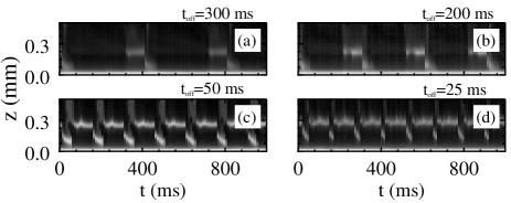
Since the modulation plays an important role in film deposition, we study the particle dynamics with various plasma-off times. The results are shown in Fig. 3. For and ms, the plasma-off phase is long enough that almost all dust particles can reach the substrate. However, when the time of the plasma-off phase is shorter than the critical time ( ms), the next discharge ignites before most particles reach the substrate. The particles are moved back to the sheath edge, and thus the deposition process is inhibited by the fast formation of the sheath in the plasma.
We study the morphology of the TiO2 films deposited for minutes under the scanning electron microscope (SEM). Images of the surface and the cross section of the films deposited with five plasma-off times are shown in Fig. 4(a-e). For and ms, the surface morphology of the film is rather similar, as shown in Fig. 4(a,b). As decreases, the ratio of big particles to small particles increases. For ms, only big particles can be seen as constituents of the film, as shown in Fig. 4(e). This trend is clearly demonstrated in the distribution of particle diameters shown in Fig. 4(f). The peak lies at about nm for and ms, similar to the size distribution of the particles collected at the gas exit, as shown in Fig. 1(d). However, the peak shifts to larger diameter and becomes broader as decreases. Here only the bigger particles (with higher probability of being charged) get accelerated enough that they can reach the substrate within the limited time of the plasma-off phase. Most particles, in particular those with small size, are turned back to the sheath as the plasma is ignited after the very short off time.
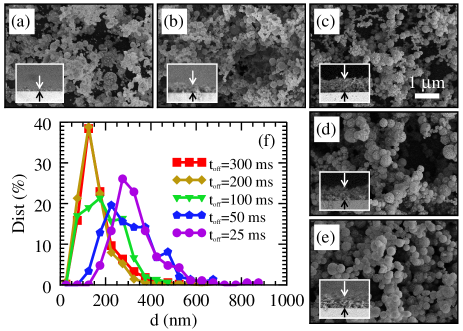
As a consequence of the particle dynamics, the thickness of the film varies considerably with the plasma-off time, as shown in the insets of Fig. 4. Here we measure the TiO2 film thicknesses and mean particle diameters with a total deposition time of minutes. As we can see in Fig. 5, the film thickness first increases from m to m as increases up to ms. It then decreases to m for ms. Two factors influence the film thickness, i.e., the repetition frequency and the duration of the plasma-off phase. On the one hand, a longer plasma-off time leads to fewer repetitions within a certain time period. For , , ms, almost all particles can be deposited on the substrate within each repetition. Therefore, the more repetitions there are, the thicker the film is. On the other hand, a shorter plasma-off phases prevents small particles from reaching the substrate. Consequently, fewer particles are deposited on the substrate in each repetition. This causes the thinner film as further decreases below ms. As to the size of the particles in the porous film, the mean diameter keeps relatively stable for ms and increases as a shorter plasma-off time is applied, as shown by the diamond symbols in Fig. 5. Based on these factors, we can describe the dependence of the film thickness on the plasma-off time with a phenomenological formula:
| (1) |
where is the ratio of the plasma-off time to the plasma-on time. The formula is composed of three terms, where the first term, , is associated with the repetition frequency, the second term, , represents the effect of particle sizes, and the third term, , is the cumulative (normal) distribution function 222The cumulative distribution function should approach one as exceeds the critical time . The formula (1) is fitted to the measured film thickness and its second term is fitted to the mean particle diameter , resulting in the fitting parameters as , m, m, , and . As we can see in Fig. 5, this formula provides a good agreement to the experimental results.

In summary, we apply a pulse modulation to overcome the particle trapping effect and successfully prepare porous TiO2 films in an rf atmospheric plasma glow discharge. In contrast to film deposition by plasma-jet Homola et al. (2016), the thickness and the structure of the porous films can be controlled directly by tuning the discharge parameters such as the plasma-off time. Using video microscopy, we directly observe the collective dynamics of particles during the deposition, revealing the whole process at the most fundamental “kinetic” level. Besides, the formation of the plasma sheath at the ignition is monitored using particles as diagnostics, showing a fair agreement with the numerical simulations. This work sheds light on the microscopic mechanism of the plasma assisted porous film deposition and extends its application to various fields requiring fine control.
Acknowledgements.
The authors acknowledge support from the National Natural Science Foundation of China (NSFC), Grant No. 11405030, 10775031, and 10835004. We thank Michael A. Lieberman and Hubertus M. Thomas for the valuable suggestions.References
- Burschka et al. (2013) J. Burschka, N. Pellet, S. Moon, R. Humphry-Baker, P. Gao, M. K. Nazeeruddin, and M. Grätzel, Nature 499, 316 (2013).
- Chen et al. (2009) D. Chen, F. Huang, Y. Cheng, and R. A. Caruso, Advanced Materials 21, 2206 (2009).
- Qin et al. (2018) S. Qin, M. Wang, C. Wang, Y. Jin, N. Yuan, Z. Wu, and J. Zhang, Advanced Materials Interfaces 5, 1800579 (2018).
- Kimura et al. (2012) M. Kimura, R. Sakai, S. Sato, T. Fukawa, T. Ikehara, R. Maeda, and T. Mihara, Advanced Functional Materials 22, 469 (2012).
- Liu et al. (2013) L. Liu, X. Li, P. K. Dutta, and J. Wang, Sensors and Actuators B: Chemical 185, 1 (2013).
- Varshney et al. (2016) G. Varshney, S. R. Kanel, D. M. Kempisty, V. Varshney, A. Agrawal, E. Sahle-Demessi, R. S. Varma, and M. N. Nadagoud, Coordination Chemistry Reviews 306, 43 (2016).
- Justicia et al. (2002) I. Justicia, P. Ordejón, G. Canto, J. L. Mozos, J. Fraxedas, G. A. Battiston, R. Gerbasi, and A. Figueras, Advanced Materials 12, 1399 (2002).
- Boysen et al. (2018) N. Boysen, T. Hasselmann, S. Karle, D. Rogalla, D. Theirich, M. Winter, T. Riedl, and A. Devi, Angewandte Chemie International Edition 57, 16224 (2018).
- Massines et al. (2012) F. Massines, C. Sarra-Bournet, F. Fanelli, N. Naudé, and N. Gherardi, Plasma Processes and Polymers 9, 1041 (2012), ISSN 16128850.
- Shi and Kong (2006) J. J. Shi and M. G. Kong, Phys. Rev. Lett 96, 105009 (2006).
- Hodgkinson and Sheel (2013) J. L. Hodgkinson and D. W. Sheel, Surface and Coatings Technology 230, 73 (2013).
- Li et al. (2019) D. Li, S. Bulou, N. Gautier, S. Elisabeth, A. Goullet, M. Richard-Plouet, P. Choquet, and A. Granier, Applied Surface Scienc 466, 63 (2019).
- Baba et al. (2017) K. Baba, S. Bulou, P. Choquet, and N. D. Boscher, ACS Appl. Mater. Interfaces 9, 13733 (2017).
- Selwyn et al. (1989) G. S. Selwyn, J. Singh, and R. S. Bennett, Journal of Vacuum Science & Technology A 7, 2758 (1989).
- Selwyn. et al. (1990) G. S. Selwyn., J. E. Heidenreich, and K. L. Haller, Applied Physics Letters 57, 1876 (1990).
- Bazinette et al. (2016) R. Bazinette, J. Paillol, J.-F. Lelièvre, and F. Massines, Plasma Processes and Polymers 13, 1015 (2016).
- Fortov et al. (2005) V. E. Fortov, A. V. Ivlev, S. A. Khrapak, A. G. Khrapak, and G. E. Morfill, Physics Reports 421, 1 (2005).
- Shukla and Mamun (2002) P. Shukla and A. Mamun, Introduction to Dusty Plasma Physics (Institute of Physics Publishing, Bristol and Philadelphia, 2002).
- Bouchoule (1999) A. Bouchoule, ed., Dusty Plasmas: Physics, Chemistry, and Technological Impact in Plasma Processing (Wiley, Chichester, 1999).
- Morfill and Ivlev (2009) G. E. Morfill and A. V. Ivlev, Rev. Mod. Phys. 81, 1353 (2009).
- Chaudhuri et al. (2011) M. Chaudhuri, A. V. Ivlev, S. A. Khrapak, H. M. Thomas, and G. E. Morfill, Soft Matter 7, 1287 (2011).
- Kryuchkov et al. (2018a) N. P. Kryuchkov, S. O. Yurchenko, Y. D. Fomin, E. N. Tsiok, and V. N. Ryzhov, Soft Matter 14, 2152 (2018a).
- Thomas and Morfill (1996) H. M. Thomas and G. E. Morfill, Nature 379, 806 (1996).
- Rubin-Zuzic et al. (2006) M. Rubin-Zuzic, G. E. Morfill, A. V. Ivlev, R. Pompl, B. A. Klumov, W. Bunk, H. M. Thomas, H. Rothermel, O. Havnes, and A. Fouquet, Nat. Phys. 2, 181 (2006).
- Tsai et al. (2016) Y.-Y. Tsai, J.-Y. Tsai, and L. I, Nat. Phys. 12, 573 (2016).
- Wong et al. (2018) C.-S. Wong, J. Goree, Z. Haralson, and B. Liu, Nat. Phys. 14, 21 (2018).
- Kryuchkov et al. (2018b) N. P. Kryuchkov, E. V. Yakovlev, E. A. Gorbunov, L. Couëdel, A. M. Lipaev, and S. O. Yurchenko, Phys. Rev. Lett. 121, 075003 (2018b).
- Thomas (1999) E. Thomas, Physics of Plasmas 6, 2672 (1999).
- Thomas et al. (2004) E. Thomas, J. D. Williams, and J. Silver, Physics of Plasmas 11, L37 (2004).
- Schlebrowski et al. (2013) T. Schlebrowski, H. Bahre, M. Boke, and J. Winter, Plasma Sources Science and Technology 22, 065014 (2013).
- Barbosa et al. (2015) S. Barbosa, L. Couëdel, C. Arnas, K. K. Kumar, C. Pardanaud, and F. R. A. Onofri, Journal of Physics D: Applied Physics 49, 045203 (2015).
- Du et al. (2017) C.-R. Du, V. Nosenko, H. M. Thomas, A. Muller, A. M. Lipaev, V. I. Molotkov, V. E. Fortov, and A. V. Ivlev, New Journal of Physics 19, 073015 (2017).
- Mitic et al. (2018) S. Mitic, S. Coussan, C. Martin, and L. Couëdel, Plasma Processes and Polymers 15, 1700152 (2018).
- Mikikian et al. (2016) M. Mikikian, S. Labidi, E. von Wahl, J. F. Lagrange, T. Lecas, V. Massereau-Guilbaud, I. Géraud-Grenier, E. Kovacevic, J. Berndt, H. Kersten, et al., Plasma Physics and Controlled Fusion 59, 014034 (2016).
- Berndt et al. (2009) J. Berndt, E. Kovacevic, I. Stefanovic, O. Stepanovic, S. H. Hong, L. Boufendi, and J. Winter, Contributions to Plasma Physics 49, 107 (2009).
- Couëdel et al. (2010) L. Couëdel, M. Mikikian, A. A. Samarian, and L. Boufendi, Physics of Plasmas 17, 083705 (2010).
- Mikikian et al. (2010) M. Mikikian, L. Couëdel, M. Cavarroc, Y. Tessier, and L. Boufendi, Phys. Rev. Lett. 105, 075002 (2010).
- Khrapak et al. (2002) S. A. Khrapak, A. V. Ivlev, G. E. Morfill, and H. M. Thomas, Physical Review E 66, 046414 (2002).
- Schwabe et al. (2014) M. Schwabe, S. Zhdanov, C. Räth, D. B. Graves, H. M. Thomas, and G. E. Morfill, Phys. Rev. Lett. 112, 115002 (2014).
- Rubin-Zuzic et al. (2007) M. Rubin-Zuzic, H. M. Thomas, S. K. Zhdanov, and G. E. Morfill, New Journal of Physics 9, 39 (2007).
- Annaratone et al. (2004) B. M. Annaratone, T. Antonova, H. M. Thomas, and G. E. Morfill, Phys Rev Lett 93, 185001 (2004).
- Annaratone et al. (2003) B. M. Annaratone, M. Glier, T. Stuffler, M. Raif, H. M. Thomas, and G. E. Morfill, New Journal of Physics 5, 92 (2003).
- Kersten et al. (2003) H. Kersten, R. Wiese, G. Thieme, M. Fröhlich, A. Kopitov, D. Bojic, F. Scholze, H. Neumann, M. Quaas, H. Wulff, et al., New Journal of Physics 5, 93 (2003).
- Basner et al. (2009) R. Basner, F. Sigeneger, D. Loffhagen, G. Schubert, H. Fehske, and H. Kersten, New Journal of Physics 11, 013041 (2009).
- Ding et al. (2014a) K. Ding, M. A. Lieberman, A. J. Lichtenberg, J. J. Shi, and J. Zhang, Plasma Sources Science and Technology 23, 065048 (2014a).
- Ding et al. (2014b) K. Ding, M. A. Lieberman, and A. J. Lichtenberg, Journal of Physics D: Applied Physics 47, 305203 (2014b).
- Lazzaroni et al. (2012) C. Lazzaroni, P. Chabert, M. A. Lieberman, A. J. Lichtenberg, and A. Leblanc, Plasma Sources Science and Technology 21, 035013 (2012).
- Khrapak et al. (2006) S. A. Khrapak, G. E. Morfill, A. G. Khrapak, and L. G. D’yachkov, Physics of Plasmas 13, 052114 (2006).
- Khrapak and Morfill (2009) S. Khrapak and G. Morfill, Contributions to Plasma Physics 49, 148 (2009).
- Ellis et al. (1976) H. Ellis, R. Pai, E. McDaniel, E. Mason, and L. Viehland, Atomic Data and Nuclear Data Tables 17, 177 (1976).
- Homola et al. (2016) T. Homola, P. Dzik, M. Vesely, J. Kelar, M. Černák, and M. Weiter, ACS Appl. Mater. Interfaces 8, 33562 (2016).