Dynamical coupling between connected foam films by interface transfer across the menisci
Abstract
The highly confined flow of the liquid phase, trapped between the gas bubbles, is at the origin of the large effective viscosity of the liquid foams. Despite the industrial relevance of this complex fluid, the foam viscosity remains difficult to predict, because of the lack of flow characterization at the bubble scale. Using an original deformable frame, we provide the first experimental evidence of the interface transfer between a compressed film (resp. a stretched film) and its first neighbour, across their common meniscus. We measure this transfer velocity, which is a key boundary condition for local flows in foams. We also show the dramatic film thickness variation induced by this interface transfer, which may play an important role in the film thickness distribution of a 3D foam sample.
pacs:
47.15.gm,47.55.dk,82.70.Rr,82.70.Uv,83.50.LhDry liquid foams are made of thin liquid films connected with each other by menisci. Considering the foam at the millimetric scale of few bubbles, most of the mechanical properties can be understood by modelling the thin films and the menisci respectively as 2D surfaces and 1D lines. The obtained geometrical shape, simply called the foam shape hereafter, is a minimal surface and obeys the Plateau rules Plateau (1873) if the gravity, inertia and viscous forces are negligible, and if the surface tension is homogeneous Cantat et al. (2013). Under slow imposed deformation, the foam shape follows the evolution of the external constraint, still obeying the Plateau rules: this is the well known elasto-plastic regime Höhler and Cohen-Addad (2005). In this regime, the normal motion of the different films fully determines the mechanical response of the foam; the tangential velocities on the interfaces remain unknown and irrelevant, entirely decoupled from the observed dynamics.
At higher deformation rate, in contrast, tangential velocities become crucial, as they are strongly coupled to the viscous forces and surface tension variations which govern the dynamics. In this viscous regime, foam dynamics at the local scale has been partially characterized in the literature: interfacial stress have been determined by a measure of the angles between adjacent films during imposed deformation Durand and Stone (2006); Besson and Debrégeas (2007); Biance et al. (2009); Zaccagnino et al. (2018) or by force measurements Costa et al. (2013a); film thicknesses have been measured by interferometry Seiwert et al. (2013) or light absorption Petit et al. (2015); and velocities in a stretched film by particle tracking Petit et al. (2015). These measurements provide important information, but are not exhaustive enough to fully determine the flow in the liquid phase. Especially, the amount of interface area which is transferred from one film to its first neighbour during a film deformation, or which is created/destroyed in the meniscus, has never been measured, and is a key parameter in all the current predictions of foam dissipation Besson et al. (2008); Denkov et al. (2009); Costa et al. (2013b); Titta et al. (2018); Zaccagnino et al. (2018). The principal aim of the paper is to provide the first measurement of the tangential velocities on both sides of a given meniscus, and especially the tangential velocity induced in a film by the deformation of its first neighbour. This measure is synchronized with thickness film and foam shape measurements, during a well controlled deformation.
A dedicated deformable frame, schematized Fig. 1, has been designed on which five connected foam films are produced. The central one has a horizontal rectangular shape; its short edges, of length mm and oriented along , are the central part of the two X-shaped metallic pieces constituting the lateral boundaries of the system; its long edges, oriented along are two free menisci of length mm, each of them being connected to two other rectangular films, called the lateral films and labelled by the index (see Fig. 1).
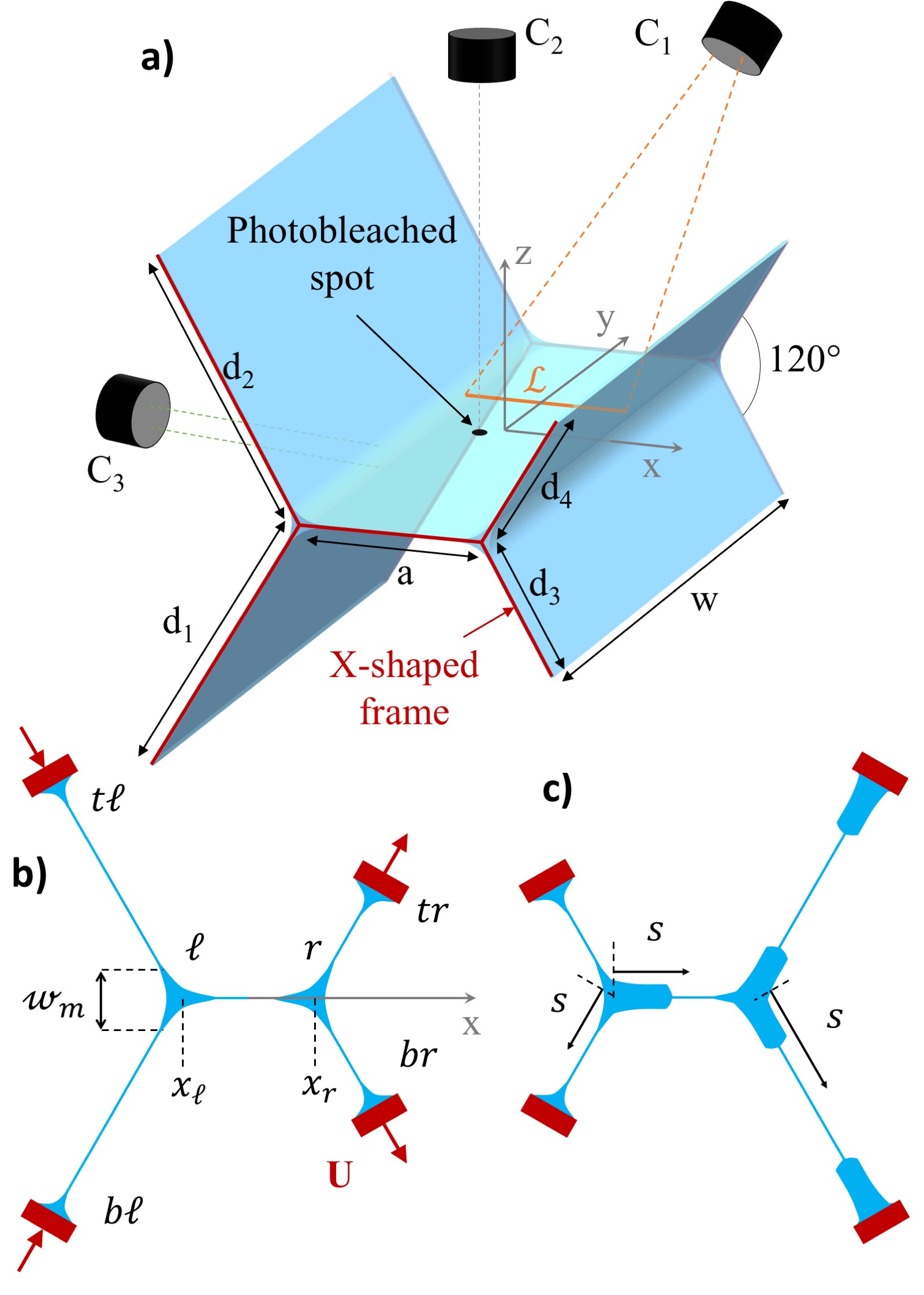
The lateral films make an angle of 120o with the central film and their external edges are a metallic segment of length which can translate along the lateral arms of the X-shaped pieces. The distance between the moving edge and the corresponding meniscus is controlled by a linear piezo motor (PI U-521.23). This geometry has been chosen so that each film remains flat and stay in the same plane during the deformation. In this study, we impose on the left side and on the right side, between and . The four motors stop after a displacement of mm, at time s. The motor velocity is mm/s and mm. Syringes positioned along the four upper arms of the X-shaped pieces each injects a flux mL/min of surfactant solution in the system. This allows to prepare a reproducible initial state for the films and menisci, which are deformed 15 s after being pulled at a controlled velocity out of the foaming solution.
The solution is made of deionised water, sodium dodecyl sulfate (SDS, cmc = g/L) at g/L, dodecanol at g/L, glycerol at in volume and fluorescein at g/L. The viscosity is mPa.s, and the equilibrium surface tension is mN/m.
The most extensive set of data has been obtained in the central film, and reveals that the deformation of the lateral films induce an important flow in the central film, as well as a strong swelling, even if the central film area is not modified. This unexpected dynamical behavior has been fully characterized by 3 synchronized cameras.
The central film thickness is measured along a line oriented along , with a spectral camera Resonon Pika L (camera ) used at a frame rate of im/s. This camera records light spectrum along the vertical lines of the sensor, each point of corresponding to a different sensor line (see Supp. Mat. A SM ). The thickness is extracted by using the relation , with the water refractive index and the incidence angle.
Film thickness profiles have also been obtained in the bottom lateral films, hereafter denoted by the left and right films.
The velocity field is deduced from the motion of photobleached spots Seiwert et al. (2017). A laser of wavelength nm and power mW is focused on the film with a normal incidence, during ms. The fluorescein is photobleached over the whole film thickness in a cylindrical region of diameter m. A large part of the film is illuminated at the same wave length and the light of wavelength between and nm emitted by the fluorescein is recorded with a camera placed above the setup (camera ). For each experiment, a single spot is photobleached 10 ms before motor motion, and its position is followed during few seconds (unless it reaches the central film boundaries before). The velocity remains uniform across the central film thickness because (i) the pressure is the ambient pressure in the flat part of the film, preventing any Poiseuille flow; (ii) the symmetry of the system and of the imposed deformations implies identical velocities on both interfaces, preventing any shear flow. Moreover the experimental time is shorter than the fluorescein diffusion time. Consistently the spot remains well contrasted along its whole trajectory and is a good passive tracer.
This camera is also used to track the positions and , of the left and right menisci, respectively. They slightly move during the deformation, without modifying significantly the central film area. In the central film, we denote by the distance to the left meniscus, i.e. , while in the lateral films is the distance to the corresponding free meniscus (see Fig. 1)c.
Finally, the vertical dimension of the left meniscus is recorded by light transmission using a collimated white light and a telecentric objective Edmund optic Silver-TL 4x (camera ). The vertical position of the meniscus remains almost constant, with variations less than m.
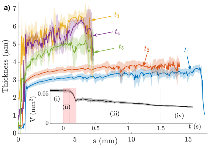
The thickness profiles during and after motor motion are shown in Fig. 2 for different times, in the central, left and right films, evidencing the following phenomenology :
(i) Initial state . The central film thickness is uniform and equal to nm. The left film is 3 m thick and the right film is 1.5 m thick. These last thicknesses have steady but out of equilibrium values, which depend on the film size and inclination, and on the injected flux. The meniscus radius of curvature is deduce from the equilibrium relationship m Cantat et al. (2013).
(ii) Lateral films stretching and compression ( s). The right film get thinner and the left film get thicker, but their volumes remains constant. This evidences a homogeneous films deformation with no exchange with the menisci. No noticeable evolution is observed in the central film.
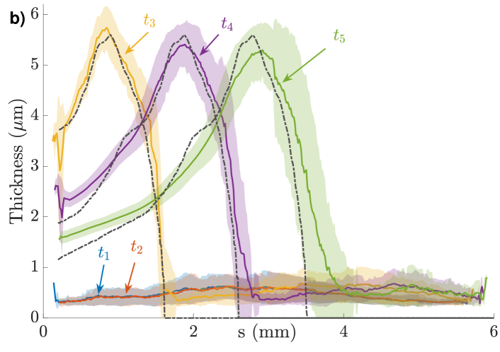
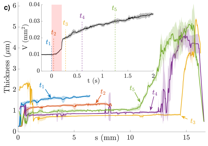
(iii) Interface transfer across menisci ( s). In the right film, thick pieces of film, called the Frankel’s films, are extracted from both the right and bottom right menisci (see Fig. 1c). A straight, well defined, frontier separates these Frankel’s films from the film initially present (hereafter called the initial film). The total film volume increases, while the initial film keeps a constant volume, and a homogeneous and increasing thickness; symmetrically, the left film get thinner and its volume decreases, evidencing a liquid flux toward the left and bottom left menisci. A similar behavior is observed in the top lateral films. Note that during steps (ii) and (iii) the thickness in the left film and in the right initial film evolves non-monotonically, as shown in Fig. 1 of the Sup. Mat. SM . In the central film, a Frankel’s film is extracted from the left meniscus and the thin film initially present flows into the right meniscus. This step (iii) begins while the motors are still moving, but lasts for few second after motors stop at s. The top/bottom symmetry of the motion in the right film is broken at s by a gravitational instability which imposes a stratification of the film thickness, thicker parts of the film laying below the thinner parts. A single Frankel’s film is thus observed at later times in the right film, close to the bottom meniscus. The Frankel’s film is however continuously produced at the top, but it falls down after its extraction from the meniscus and merges with the Frankel’s film produced at the bottom (see Shabalina et al. (2018)). The downwards motion of patches of thick films induces recirculations in the central part of the stretched film, thus forbidding reliable velocity measurements in this lateral film.
(iv) Eventually, the system recovers its slow drainage behavior, after a delay of the order of 10 s.
The Frankel’s film extraction in the central film is due to the motion of the interfaces across the left and right menisci, which we determine from the velocity measurements. We measured the spots position relatively to the left meniscus . The displacement of the spots in the direction remains smaller than of the total spot displacement, except for positions very close from the right meniscus, where we observe marginal regeneration which locally breaks the invariance in the direction Mysels et al. (1959). In the following, the spots at a distance smaller than 1 mm from the right meniscus are discarded. We recorded 4 trajectories , each being averaged over 10 experiments. The index refers to the initial distance between the spots (i) and the left meniscus, ranging from 1 to 4 mm.
These trajectories evidence a translational motion of the central film, with almost no deformation, over a distance which is a significant fraction of the motor displacement. Fig. 3(inset) shows the distance between spots and the spots as a function of time. The spots and are close to the left meniscus, and the distance between them is almost conserved during the whole motion, showing the absence of film deformation in this region. The distances between spots (3,4) and spots (1) slightly decrease, indicating a small film compression in the right part of the film. However, no clear signature of this compression is observable in the thickness map (Fig. 2b), and residual recirculations close to the right meniscus may be at the origin of this small drift, especially at the longest times.
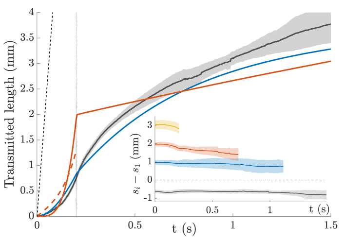
The trajectory of spots relatively to their initial position, i.e. the distance , is plotted in Fig. 3. As the central film moves as a whole close to the left meniscus, corresponds to the amount of film extracted from the left meniscus. If we neglect the small compression observed close to the right meniscus, it corresponds also to the amount of film absorbed by the right meniscus.
In the left and right films, the interface length transmitted across the meniscus is determined from the thickness profile. On both sides, we assume that the same amount of interface goes in (or out) the top and bottom meniscus bounding the lateral film. In that case, we establish in Supp. Mat. B SM that:
| (1) |
with the film velocity at the free meniscus and the film extension. The average is made respectively on the whole left film, and on the thin part of the right film. Then we define .
In the right film, the top and bottom Frankel films have the same width before the instability begins, thus confirming the validity of our symmetry assumption, at least at short time. In the left film, a spot trajectory has been obtained, again at short time, allowing to compute as , which does not requires any symmetry assumption (see Supp. Mat. B SM ). The prediction is in qualitative agreement with , as shown in Fig. 3.
The quantity is determined with an error bar smaller than 10 . and (or ) have a larger uncertainty at large time, due to the assumption of symmetric behavior we need to make. However, they show a behavior very similar to with time (Fig. 3). A first conclusion is thus that the motor displacements lead to the transfer of interface from the left film to the right film across the two free menisci and the central film, occurring with negligible in-plane deformation, and with some delay with respect to the motor motion. The amount of interface transferred after 1 s is of the order of 3 mm, which is a significant part of the 10 mm displacement of the motor.
This interface transfer across the central film is coupled to the extraction of a Frankel’s film from the left meniscus. After few seconds, it entirely invades the central film which is, thus, strongly modified by the deformation, even if its area remains unchanged: the extracted film is one order of magnitude thicker than the film initially present. It is separated from the thin film by a sharp frontier, moving at the velocity (see Fig. 3 inset).
The thickness of the film extracted from a meniscus of radius , at a constant velocity is given by the Frankel’s expression , with Mysels et al. (1959). In the central film, the dynamical meniscus lateral extension scales as m and the film goes through this region in a time s, much smaller than the time scale of the velocity variation s (see Fig. 3). An approximation of quasi steady motion is thus justified. The thickness gradient at the frontier is of the order of and it decreases on the typical time scale s Chai et al. (2014), the diffusion of the step-like frontier thus occurs on a slower timescale than the experiment. Once extracted from the meniscus, the film thus simply follows a passive convection. Moreover, as the central film extension rate is negligible, it moves without any deformation. As a consequence, the film at the position at time has been extracted from the meniscus at time implicitly given by the relation , and the theoretical prediction for its thickness is
| (2) |
The quantitative agreement shown in Fig. 2 between this prediction, obtained without adjustable parameter, and the experimental data, validates a posteriori the assumptions of the Frankel’s model.
In conclusion, the imposed deformation induces a thickness increase by a factor of 10 in a film which is only a neighbour of the deformed films. The thickness relaxation toward its initial value last for several seconds. We believe that the localized deformations occurring in 3D foam samples, due to aging or global flow, may redistribute the liquid phase in the thin films at a much larger distance from the local deformation than previously expected. This process is potentially an efficient factor of rejuvenation of the foam films, competing with the slow drainage imposed by the meniscus capillary suction and gravity. The original set-up we developed proved, on the example of the imposed deformation we choose, its capacity to identify deformation modes in foam films, and to measure them with an accuracy allowing for a quantitative comparison with local theoretical models. We believe this should remains the case for a large class of imposed deformations, which paves the way to a deeper understanding of dissipation in foams.
Acknowledgements.
This project has received funding from the European Research Council (ERC) under the European Union’s Horizon 2020 research and innovation program (grant agreement No 725094). We thank A. Saint-Jalmes and A. Bérut for fruitful discussions and E. Schaub for technical support.References
- Plateau (1873) J. A. F. Plateau, Statique expérimentale et théorique des liquides soumis aux seules forces moléculaires (Gauthier-Villard, Paris, 1873).
- Cantat et al. (2013) I. Cantat, S. Cohen-Addad, F. Elias, F. Graner, R. Höhler, O. Pitois, F. Rouyer, and A. Saint-Jalmes, Foams. Structure and Dynamics, edited by S. Cox (Oxford University Press, Oxford, 2013).
- Höhler and Cohen-Addad (2005) R. Höhler and S. Cohen-Addad, J. Phys.: Condens. Matter 17, R1041 (2005).
- Durand and Stone (2006) M. Durand and H. Stone, Phys. Rev. Lett. 97, 226101 (2006).
- Besson and Debrégeas (2007) S. Besson and G. Debrégeas, Eur. Phys. J. E 24, 109 (2007).
- Biance et al. (2009) A. L. Biance, S. Cohen-Addad, and R. Höhler, Soft Matter 5, 4672 (2009).
- Zaccagnino et al. (2018) F. Zaccagnino, A. Audebert, and S. J. Cox, Phys. Rev. E 98, 022801 (2018).
- Costa et al. (2013a) S. Costa, S. Cohen-Addad, A. Salonen, and R. Höhler, Soft Matter 9, 886 (2013a).
- Seiwert et al. (2013) J. Seiwert, M. Monloubou, B. Dollet, and I. Cantat, Phys. Rev. Lett. 111, 094501 (2013).
- Petit et al. (2015) P. Petit, J. Seiwert, I. Cantat, and A.-L. Biance, J. Fluid Mech. 763, 286 (2015).
- Besson et al. (2008) S. Besson, G. Debrégeas, S. Cohen-Addad, and R. Höhler, Phys. Rev. Lett. 101, 214504 (2008).
- Denkov et al. (2009) N. D. Denkov, S. Tcholakova, K. Golemanov, and A. Lips, Phys. Rev. Lett. 103, 118302 (2009).
- Costa et al. (2013b) S. Costa, R. Höhler, and S. Cohen-Addad, Soft Matter 9, 1100 (2013b).
- Titta et al. (2018) A. Titta, M. Le Merrer, F. Detcheverry, P. Spelt, and A.-L. Biance, J. Fluid Mech. 838, 222 (2018).
- (15) See Supplemental Material at xxx for information about the spectral camera and the calculation of the transmitted interface length.
- Seiwert et al. (2017) J. Seiwert, R. Kervil, S. Nou, and I. Cantat, Phys. Rev. Lett. 118, 048001 (2017).
- Shabalina et al. (2018) E. Shabalina, A. Bussonnière, M. Cavelier, A. Bérut, A. Saint-Jalmes, and I. Cantat, Gallery of Fluid Motion /10.1103/APS.DFD.2018.GFM.V0035 (2018).
- Mysels et al. (1959) K. J. Mysels, K. Shinoda, and S. Frankel, Soap films: Study of their thinning and a bibliography (Pergamon, New-York, 1959).
- Chai et al. (2014) Y. Chai, T. Salez, J. D. McGraw, M. Benzaquen, K. Dalnoki-Veress, E. Raphaël, and J. A. Forrest, Science 343, 994 (2014).