Comparison of the lateral retention forces on sessile, pendant, and inverted sessile drops
Abstract
We compare the lateral retention forces on sessile drops (which are drops that are placed on top of a solid surface), pendant drops (which are drops that are placed on the underside of the surface), and inverted sessile drops (which are drops that are first placed on top and then on the underside of the surface by flipping the surface). We have found experimentally that the retention force on a truly pendant drop is always smaller than that on a sessile drop. However, the retention force on an inverted sessile drop is comparable to, and usually larger than, that on a sessile drop. Thus, the retention force on a drop depends not only on whether it is placed on top or on bottom of a surface, but also on the history of drop deposition, since such history affects the width, the shape and the contact angles of the drop.
1 Introduction
The study of liquid drops on solid substrates has attracted a great deal of attention [1, 2, 3], because of both its scientific interest and its industrial applications. However, there are many aspects of wetting and dewetting phenomena that are still not well understood. One such aspect was reported in Ref. [4], where Tadmor et al. presented a very counterintuitive property of the lateral retention force on liquid droplets at the moment the droplets start to slide on a solid surface. Contrary to the solid-solid friction case, a drop hanging from a solid surface experiences a larger retention force than a drop resting on the surface [4]. In spite of the attention it drew [5, 6], the origin of this effect remains unknown.
The purpose of this paper is to put forward an explanation of the effect observed in Ref. [4]. We will argue that the origin of such effect is rooted on how the drops are formed. We will distinguish between sessile drops (which are drops that are formed by placing a small amount of liquid on top of a uniform, flat, solid surface), pendant drops (which are drops that are formed by placing the liquid on the underside of the surface), and inverted sessile (or simply inverted) drops (which are drops that are formed by placing the liquid on top of the surface, and then placing it on the underside by flipping the surface). We have found that the retention force on a truly pendant drop is smaller than that on a sessile drop, just as naive intuition suggests. We have also found that the retention force on an inverted sessile drop is comparable to, and usually larger than, that on a sessile drop. This result may explain the effect observed in Ref. [4], because the drops placed on the underside of the solid substrate in Ref. [4] were not truly pendant drops, but rather inverted sessile drops.
2 Experimental Section
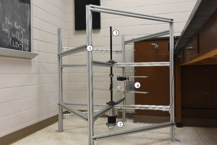
Our experimental apparatus is a simplified version of the Centrifugal Adhesion Balance [4] and the Kerberos drop accelerator [7, 8, 9]. It consists of a metallic frame with dimensions inside of which the rotary unit is mounted, see Fig. 1. The four legs of the frame are bolted to the floor to reduce mechanical vibrations. The rotary unit consists of a servo motor [10], a shaft, and two pairs of aluminum rails that are attached perpendicularly to the shaft. The motor is connected to a power supply and a computer, whose software controls the motor.
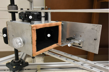
A metallic box is mounted on the aluminum rails. The box has two cameras placed on top and on the side, which provide top and side views of the drops, see Fig. 2. A remote-controlled LED is used to set a common starting time in the videos of the cameras. On the door of the metallic box, we mounted a poly methyl methacrylate (PMMA) sheet (Optix®, by Plaskolite) such that, when a drop is placed on the sheet and the door is closed, the cameras have side and top views of the drop. Illumination for the side camera is provided by the remote-controlled LED. Lighting for the top camera is provided by an LED panel and an optical gradient [11]. To remove any remnants of their protective films, the PMMA sheets were initially washed with hot water and soap. Afterward, before each run, the PMMA sheets were cleaned with 70% isopropyl alcohol and paper tissue [12], and dried with lamplight.
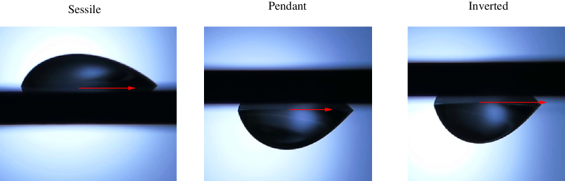
To place the water droplets on the PMMA sheet, we used a micropipette [13]. A sessile (pendant) drop was formed by slowly releasing the contents of the micropipette on top (bottom) of the PMMA sheet. An inverted sessile drop was formed by slowly releasing the contents of the micropipette on top of the PMMA sheet, and then flipping the sheet, so the drop ends up on the underside of the sheet. Figure 3 shows 30-L sessile, pendant, and inverted sessile drops at rest. Clearly, an inverted sessile drop is not the same as a pendant drop. In particular, the width of the inverted sessile drop is larger than that of a pendant drop, but comparable to the width of the sessile drop. As we will see, the width is the main factor that differentiates the retention forces on sessile, pendant, and inverted sessile drops.
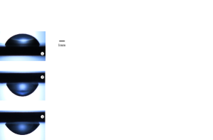
To make the drops slide on the PMMA sheet, we rotated the box with a constant angular acceleration of about 0.086 rad/s2. As the angular velocity of the drop increases, the centrifugal force increases [14]. This eventually makes the advancing edge of the drop crawl forward in the radial direction, although the receding edge of the drop stays pinned to the surface [8]. While the advancing edge crawls forward, the triple line deforms slightly from its initial circular shape. At some point, when the centrifugal force is large enough, the receding edge of the drop also starts moving in the outward, radial direction. When that happens, the whole drop moves in the outward, radial direction [8]. This is why we identify the onset of the motion of the drop with the instant at which the receding (i.e., trailing) edge of the drop starts moving.
We used the videos of the side camera and custom-made software to determine the instant when the receding edge of the drop starts moving. At such instant, we obtained the contact angles from the videos of the side-view camera using ImageJ [15], and the width from the videos of the top-view camera using PixelZoomer [16].
3 Results and Discussion
3.1 Experimental Results
We measured the time it took each drop to start sliding on the PMMA sheet for each type of drop (sessile, pendant, and inverted sessile), for each volume (15, 20, 25, and 30 L), and for twelve different PMMA sheets. For volumes larger than 30 L, it is hard to produce inverted drops, because big drops slide on the surface during the flip. Hence, for 40-100 L volumes, we analyzed only sessile and pendant drops at intervals of 10 L. Using the times at which the onset of the motion occurs, we obtained the lateral retention force from the centrifugal force,
| (3.1) |
where is the mass of the drop, is its density, is its volume, is the distance from the center of the drop to the axis of rotation (about 170 mm in our experiment), is the angular acceleration, and is the time since the rotation of the motor started.
For each volume and for each type of drop, we calculated the average time of about 24 runs, and we obtained that
| (3.2) |
Hence,
| (3.3) |
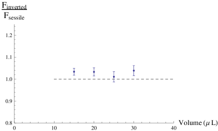
The best way to visualize Eq. (3.3) is by plotting (see Fig. 4) and (see Fig. 5), which according to Eq. (3.3) should be greater than one. It is clear from Fig. 4 that is always greater than . It is also clear that as the volume decreases, and become closer to each other. Indeed, for 100-L drops, is 18.9% larger than , but for 15-L drops, is only 2.4% larger than . This is not surprising, because the influence of gravity compared to that of surface tension decreases as the volume decreases, and therefore the drops become more alike as they become smaller.
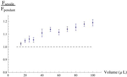
We can see in Fig. 5 that is comparable to, and usually larger than, . We can also see that, unlike Fig. 4, Fig. 5 does not show a steady decrease of the ratio as the volume decreases. What is more, for 25 L, is essentially the same as . The reason is that it is difficult to prepare inverted sessile drops by flipping a surface. In fact, unless it is done properly [12], the drop tends to slide on the surface during the flip, which may deform the drop and make it loose some of its adhesion to the surface.
Another way to rephrase Eq. (3.3) is by comparing the centrifugal accelerations at the onset of the motion, see Table 1. As can be seen in Table 1, sessile drops start sliding at a larger acceleration than pendant drops, but at a smaller acceleration than inverted drops, and hence Eq. (3.3) holds.
| Centrifugal Acceleration (m/s2) | |||||||||||
| Volume (L) | 100 | 90 | 80 | 70 | 60 | 50 | 40 | 30 | 25 | 20 | 15 |
| Sessile | 2.75 | 3.01 | 3.13 | 3.50 | 3.89 | 4.62 | 5.24 | 6.50 | 7.31 | 8.56 | 10.22 |
| Pendant | 2.32 | 2.56 | 2.71 | 3.07 | 3.49 | 4.06 | 4.72 | 6.16 | 6.89 | 8.17 | 9.97 |
| Inverted | 6.68 | 7.39 | 8.84 | 10.56 | |||||||
3.2 Systematics, troubleshooting, and reproducibility
To exclude systematic effects as the source of our results, we performed two additional experiments. One experiment was similar to that of Ref. [12], and it yielded the same results as the present paper. The other one, which can be very easily reproduced, was a simple tilted-plate experiment. We placed a sessile and a pendant drop on a PMMA surface and then slowly tilted the surface until the drops started to slide. We visually observed that, on average, the pendant drops started to slide before the sessile drops. However, when the same experiment was done with sessile and inverted sessile drops, we observed that, on average, the sessile drops started to slide before the inverted sessile drops. We also did the tilted-plate experiment with water drops on polycarbonate (Lexan) and obtained the same results.
The most important factor affecting the retention force in our experiments is how the drop is formed. While preparing the drops, the pipette needs to be perpendicular to the surface and above the same point of the surface. Otherwise, the shape and the width of the drop may change, which will affect the retention force of the drop. In addition, the procedure of Ref. [12] to build inverted drops must be followed. Overall, it is not difficult to build sessile and pendant drops that are consistently similar, but inverted sessile drops require some skill and practice.
3.3 Derivation of the theoretical retention force
To really understand our theoretical explanation of the above experimental observations, it is useful to first understand the derivation of the theoretical retention force [17, 18, 19, 20, 21, 22, 23, 24, 25, 26]. In this section, we provide such derivation. Our derivation is an improved version of the derivation provided by Dussan and Chow [22].
Let us consider a drop on a flat surface subject to an external force parallel to the surface. Three surface tensions act on a given infinitesimal section of the triple line at point P (see Fig. 6): The solid-liquid surface tension , the solid-vapor surface tension , and the liquid-vapor surface tension .
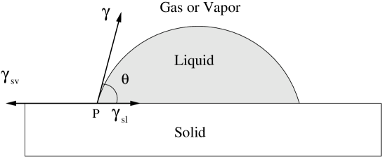
The solid-liquid and solid-vapor surface tensions act parallel to the surface, and the liquid-vapor surface tension acts at an angle with respect to the surface, where is the contact angle at that point. Thus, in the direction parallel to the surface but perpendicular to the triple line, the surface tensions acting on an element of triple line located at P are , and . When the contact angle is the Young, equilibrium angle , the net force on the element is zero, which leads to the Young equation:
| (3.4) |
When the contact angle at is not , the forces due to the surface tensions do not cancel each other,
| (3.5) |
and therefore there is a nonzero capillary force per unit of length acting on the element in the direction parallel to the surface. If we denote by the unit vector perpendicular to the triple line and pointing outwardly (see Fig. 7), then such capillary force per unit of length is given by
| (3.6) |
However, if the infinitesimal element at point P does not move, there must be a force that cancels the force in Eq. (3.6), much like when we push a solid resting on a surface but the solid doesn’t move, we say that our push is canceled by the static frictional force. The force that cancels that in Eq. (3.6) is the retention force per unit of length and is presumably due to solid-liquid-vapor interactions (compare with Eq. (6.1) in Ref. [1], Eq. (4.1) in Ref. [3], and Eqs. (11) and (12) in Ref. [24]),
| (3.7) |
Figure 7 shows the direction of the retention force at the infinitesimal element of triple line located at point P.

The net retention force on the whole drop is obtained by adding the infinitesimal retention forces acting on each infinitesimal element of the triple line :
| (3.8) |
Because , and are constant [27], and because , Eq. (3.8) simplifies to
| (3.9) |
This is the exact equation that provides the retention force on a drop resting on a uniform solid. When the contact area is symmetric with respect to the -axis, the -component of this force is zero, and therefore one only needs to worry about the -component,
| (3.10) |
To obtain the exact expression of , one needs to know
-
(i)
the exact shape of the triple line and, in particular, the variation along of the angle between and the centrifugal force, i.e., the variation of along the triple line,
-
(ii)
how the contact angle varies along the triple line.
Because it is very difficult to obtain (i)-(ii) either experimentally or theoretically, it is common to make some approximations to obtain an effective, approximate expression for the retention force that captures the essence of the exact one. One common approximation is to assume that in the “advancing half” (“receding half”) of the triple line, the contact angle remains constant and equal to the contact angle at the advancing (receding) edge of the drop, (). Within this approximation, and denoting by () the contour associated with the advancing (receding) half of the triple line, Eq. (3.10) becomes
| (3.11) | |||||
| (3.12) | |||||
| (3.13) |
where in the last step we have used [22, 26] that , being the width of the drop in the direction perpendicular to the motion of the drop, see Fig. 7.
It is clear that, in going from Eq. (3.11) to Eq. (3.12), we are making an approximation. It is also clear that what we call the “advancing” and “receding” halves is somewhat arbitrary. To correct for these approximations and still have a useful formula, it is common to introduce a shape factor in the retention force,
| (3.14) |
The shape factor carries the information lost in the approximation, that is, accounts for (i)-(ii). From a practical point of view, the shape factor is simply a fitting parameter that makes the theoretical retention force be equal to the experimental one . Hence, one can calculate in terms of experimentally measurable quantities as
| (3.15) |
One can improve the above approximation by assuming a specific variation of the contact angle along the triple line. This is what, for example, Extrand and Gent [23] and ElSherbini and Jacobi [25] did, who obtained and , respectively. It should be noted however that Refs. [23, 25] assumed that the angle between and is the same as the polar angle that locates each point on the triple line. Using an argument similar to ours, Carre and Shanahan derived Eq. (3.14) with a shape factor of .
To finish this section, we would like to note that the advancing (receding) angle is usually defined as the angle that the drop makes with the surface when the drop is inflated (deflated) [1, 3]. However, there are situations in which the contact angle at the advancing (receding) edge of the drop is not the same as when the drop is inflated (deflated) [28]. In our case, due to gravity, the contact angles at the advancing and receding edges of a sessile drop are not the same as those of pendant and inverted drops. However, as the above derivation shows, this is of no concern: Equation (3.14) simply uses the angle at the advancing () and receding () edges of the drop for the situation at hand, independently of whether such angles are different in other situations.
3.4 Theoretical explanation
According to Eq. (3.14), the three main factors that affect the retention force are the shape of the drop (), its width (), and contact angle hysteresis (). In this section, we are going to elucidate the role that each of these factors plays in differentiating the retention forces on sessile, pendant, and inverted drops.
To elucidate whether the width of the drop plays an essential role in the difference between , and , we calculated the centrifugal force per unit of width,
| (3.16) |
Because is essentially the same for sessile, pendant and inverted drops [29], we conclude that the retention force is proportional to the width of the drop. Thus, since for each volume (see Table 2), it follows that .
| Width (mm) | |||||||||||
|---|---|---|---|---|---|---|---|---|---|---|---|
| Volume (L) | 100 | 90 | 80 | 70 | 60 | 50 | 40 | 30 | 25 | 20 | 15 |
| Sessile | 9.48 | 9.15 | 8.80 | 8.51 | 8.04 | 7.83 | 6.75 | 6.18 | 5.83 | 5.44 | 4.90 |
| Pendant | 8.01 | 7.64 | 7.46 | 7.23 | 7.21 | 6.90 | 6.39 | 5.90 | 5.58 | 5.32 | 4.85 |
| Inverted | 6.21 | 5.89 | 5.86 | 5.09 | |||||||
To determine the influence of contact angle hysteresis on each type of drop, we measured the contact angles at the advancing and receding edges, and we obtained that is very similar for sessile, pendant, and inverted drops,
| (3.17) |
This result, coupled to the fact that and remain fairly constant as the volume of the drops decreases, leads us to conclude that it is unlikely that contact angle hysteresis is essential in differentiating the retention forces on sessile, pendant and inverted drops [30].
As mentioned above, the shape factor is, for practical purposes, a free parameter that allows one to fit the theoretical retention force to the experimental one . Thus, it is difficult to determine the influence of the shape of the drop on the retention force. One can nevertheless use Eq. (3.15) to obtain a value of the shape factor in terms of experimentally measurable quantities. In our experiment, we obtained that
| (3.18) |
Because these shape factors are fairly similar, it is unlikely that the shape of the triple line and the variation of the contact angle along such line are critical in determining which type of drop gets more pinned to the surface.
Thus, among the three factors that make up the retention force in Eq. (3.14), the width seems to be the one that most critically determines which kind of drop gets more pinned to the surface. Because the width of a sessile drop is larger than the width of a pendant drop (see Table 2), and because the retention force is proportional to the width, we have that is larger than . However, when we flip a sessile drop and make it an inverted sessile drop, at the onset of the motion the width is slightly larger than what it would had been for the original sessile drop (as long as the flip is done as explained in Ref. [12]), and that is what makes larger than .
One can prepare drops of a given type and volume, e.g., 80-L sessile drops, in different ways so that the widths of the drops are different. Because it is proportional to the width, the retention force should be larger for those drops with a larger width, even though they all are sessile drops of the same volume. Indeed, an experiment was done in Ref. [12] with 80-L sessile drops that were formed with different widths relative to the radial direction of the motion. It was found that the retention force increased with the width, even though the volume and the type of drop were the same. That the experiment in Ref. [12] with 80-L drops can be easily explained by saying that the retention force is proportional to the width further suggests that the width is the most critical parameter in differentiating , and , and that the retention force depends not only on whether the drop is placed on top or bottom of a solid surface, but also on the history of droplet deposition.
The lack of volume dependence in Fig. 5 can also be understood from the proportionality between the retention force and the width. Due to the way we build inverted drops, the ratio is close to unity for any volume, and therefore should always be close to unity, independently of the volume of the drop.
It is important to mention that the influence of the history of drop deposition on the retention force has been studied recently by Ríos-López et al. [8, 9], who found that one can still use Eq. (3.14) even when the drop history contains an initial stage of tilting. In their case, the relevant geometrical feature that enters Eq. (3.14) is the initial length of the drop, whereas in our case it is the width at the onset of the motion.
4 Conclusions
Using a rotating-platform experiment, we have observed that the lateral retention force on sessile drops is larger than on pendant drops, but smaller than on inverted sessile drops. We have identified the width of the drop as the critical parameter that determines this result, even though the contact angles and the shape of the triple line also affect the retention force. Because the retention force is proportional to the width, and because we built the drops such that , we have that . In general, the retention force on a drop does not depend only on whether it is placed on top or on bottom of a surface, but also on how the drop was formed. Our results can be easily reproduced, by using either a simple tilted-plate experiment or other drop accelerators [4, 7].
We would like to note that the experiment in Ref. [4] was done with a different liquid-solid combination, and for smaller volumes. We believe that our results would also be applicable to many other liquid-solid combinations for large volumes. However, for very small volumes, it might be possible that is smaller than , as long as remains constant as the volume of the drops decreases [30]. If such was the case, then contact angle hysteresis should suffice to explain why becomes smaller than . Our experiment, however, does not address the effect of the resting time on the retention force [4].
Acknowledgments
The authors thank Rafael Tadmor for many enlightening discussions. Additional thanks are due to Sage Automation, Thomas Michel, Thomas Podgorski, Taylor Whitehead, Jason Dark, Jon Klipfel, Aaron Burlew, David Jackson, Miles Stone, Jared Richards, and Al Sauerman. Financial support from a Lamar Presidential Fellowship is gratefully acknowledged.
References
- [1] de Gennes, P. G.; Brochard-Wyart, F.; Quéré, D. Capillarity and Wetting Phenomena, Springer, New York, 2004.
- [2] Erbil, H.Y. Surface Chemistry of Solid and Liquid Interfaces, Wiley-Blackwell, 2006.
- [3] Bormashenko, E. A. Wetting of Real Surfaces, Walter de Gruyter, 2013.
- [4] Tadmor, R.; Bahadur, P.; Leh, A.; N’guessan, H. E.; Jaini, R.; Dang, L. Measurement of Lateral Adhesion Forces at the Interface Between a Liquid and a Substrate. Phys. Rev. Lett. 103, 266101 (2009).
- [5] Minkel, J. R. Focus: Hanging Droplets Feel More Friction. Phys. Rev. Focus 24, 21 (2009).
- [6] Fitzgerald, R. J. A New Look at Friction. Phys. Today 63, 16 (2010).
- [7] Evgenidis, P.; Kalić, K.; Kostoglou, M.; Karapantsios, T. D. Kerberos: A Three Camera Headed Centrifugal/Tilting Device for Studying Wetting/Dewetting under the Influence of Controlled Forces. Colloids and Surfaces A: Physicochem. Eng. Aspects 521, 38-48 (2017).
- [8] Ríos-López, I.; Evgenidis, S.; Kostoglou, M.; Zabulis, X.; Karapantsios, T. D. Effect of Initial Droplet Shape on the Tangential Force Required for Spreading and Sliding Along a Solid Surface. Colloids and Surfaces A: Physicochem. Eng. Aspects 549, 164-173 (2018).
- [9] Ríos-López, I.; Karamaoynas, P.; Zabulis, X.; Kostoglou, M.; Karapantsios, T. D. Image Analysis of Axisymmetric Droplets in Wetting Experiments: A New Tool for the Study of 3D Droplet Geometry and Droplet Shape Reconstruction. Colloids and Surfaces A: Physicochem. Eng. Aspects 553, 660-671 (2018).
- [10] https://www.teknic.com
- [11] Podgorski, T.; Flesselles, J.-M.; Limat, L. Corners, Cusps and Pearls in Running Drops. Phys. Rev. Lett. 87, 036102 (2001).
- [12] de la Madrid, R.; Whitehead, T.; Irwin, G. Comparison of the Lateral Retention Forces on Sessile and Pendant Water Drops on a Solid Surface. Am. J. Phys. 83, 531-538 (2015).
- [13] Even though syringes are slightly more precise than micropipettes, we did not use them. The reason is that when we built pendant drops with a syringe, there was more liquid left in the syringe as compared to when we built sessile and inverted drops. With a micropipette, you can visually check that all the liquid has been deposited on the surface.
- [14] As the angular velocity increases, small vibrations of the apparatus produce a small trembling motion on surface of the drops. The triple line however does not seem to be significantly affected by such vibrations.
- [15] https://imagej.nih.gov/ij/
- [16] http://pixelzoomer.com
- [17] Macdougall, G.; Ockrent, C. Surface energy relations in liquid/solid systems I. The adhesion of liquids to solids and a new method of determining the surface tension of liquids. Proc. Royal Soc. Lond. A 180, 151-173 (1942).
- [18] Frenkel, Y. I. On the behavior of liquid drops on a solid surface 1. The sliding of drops on an inclined surface. J. Exp. Theo. Phys. (USSR), 18, 659-668 (1948).
- [19] Kawasaki, K. Study of wettability of polymers by sliding of water drop. J. Colloid Sci. 15, 402-407 (1960).
- [20] Furmidge, C. G. L. Studies at Phase Interfaces I. The Sliding of Liquid Drops on Solid Surfaces and a Theory of Spray Retention. J. Coll. Int. Sci. 17, 309-324 (1962).
- [21] Brown, R. A.; Orr, Jr., F. M.; Scriven, L. E. Static Drop on an Inclined Plate. Analysis by the Finite Element Method. J. Coll. Int. Sci. 73, 76-87 (1980).
- [22] Dussan, E. B.; Chow, R. T.-P. On the Ability of Drops and Bubbles to Stick to Non-Horizontal Surfaces of Solids. J. Fl. Mech. 137, 1-29 (1983).
- [23] Extrand, C. W.; Gent, A. N. Retention of Liquid Drops by Solid Surfaces. J. Coll. Int. Sci. 138, 431-442 (1990).
- [24] Carre, A.; Shanahan, M. E. R. Drop Motion on an Inclined Plane and Evaluation of Hydrophobic Treatments to Glass. J. Adhesion 49, 177-185 (1995).
- [25] ElSherbini, A. I.; Jacobi, A. M. Liquid Drops on Vertical and Inclined Surfaces; I. An Experimental Study of Drop Geometry. J. Coll. Int. Sci. 273, 556-565 (2004).
- [26] De Coninck, J.; Fernandez Toledano, J. C.; Dunlop, F.; Huillet, T. Pinning of a Drop by a Junction on an Incline. Phys. Rev. E 96, 042804 (2017).
- [27] If and were not constant along the triple line (for example, if the drop straddled the boundary between two different solids), then would not be zero, and the retention force would be provided by Eq. (3.8), not by Eq. (3.9).
- [28] Krasovitski, B.; Marmur, A. Drops Down the Hill: Theoretical Study of Limiting Contact Angles and the Hysteresis Range on a Tilted Plane. Langmuir 21, 3881-3885 (2005).
- [29] Although it remains fairly constant, has a slight tendency to increase as the volume decreases.
- [30] Due to gravity and the deformability of liquid water, the contact angles of sessile drops are about 6∘ smaller than those of pendant and inverted drops. Thus, is always a bit smaller for sessile drops. Such difference in is however not enough to upset Eq. (3.3), at least in the volume range we have studied.