Coherent Control of Two-Dimensional Excitons
pacs:
Valid PACS appear hereElectric dipole radiation can be controlled by coherent optical feedback, as has previously been studied by modulating the photonic environment for point dipoles placed both in optical cavities Purcell et al. (1946); Heinzen et al. (1987); Vredenberg et al. (1993) and near metal mirrors Drexhage et al. (1968); Drexhage (1970). In experiments involving fluorescent molecules Drexhage et al. (1968); Drexhage (1970), trapped ions Eschner et al. (2001); Wilson et al. (2003) and quantum dots Stobbe et al. (2009) the point nature of the dipole, its sub-unity quantum efficiency, and decoherence rate conspire to severely limit any change in total linewidth. Here we show that the transverse coherence of exciton emission in the monolayer two-dimensional (2D) material removes many of the fundamental physical limitations present in previous experiments. The coherent interaction between excitons and a photonic mode localized between the and a nearby planar mirror depends interferometrically on mirror position, enabling full control over the radiative coupling rate from near-zero to 1.8 meV and a corresponding change in exciton total linewidth from 0.9 to 2.3 meV. The highly radiatively broadened exciton resonance (a ratio of up to in our samples) necessary to observe this modulation is made possible by recent advances in 2D materials sample fabrication Cadiz et al. (2017); Scuri et al. (2018); Back et al. (2018). Our method of mirror translation is free of any coupling to strain or DC electric field in the monolayer, which allows a fundamental study of this photonic effect. The weak coherent driving field in our experiments yields a mean excitation occupation number of such that our experiments correspond to probing radiative reaction in the regime of perturbative quantum electrodynamics Meschede et al. (1990). This system will serve as a testbed for exploring new excitonic physics Byrnes et al. (2014) and quantum nonlinear optical effects Zeytinoǧlu et al. (2017); Wild et al. (2018).
The transition metal dichalcogenides (TMDs) and become direct band gap semiconductors when isolated in monolayer form Mak et al. (2010); Splendiani et al. (2010); Zhang et al. (2013), transferring a significant fraction of the interband spectral weight to a strong and spectrally narrow excitonic resonance Molina-Sánchez et al. (2013, 2016). Coherence Jones et al. (2013), spin-valley interactions Xiao et al. (2012); Mak et al. (2012a), strain effects Conley et al. (2013), many-body electron physics You et al. (2015); Sidler et al. (2016); Mak et al. (2012b) and engineered confinement Wang et al. (2018); Palacios-Berraquero et al. (2017) have all been studied using TMD excitons.
Monolayer and few-layer TMDs were first prepared by mechanical exfoliation Mak et al. (2010); Splendiani et al. (2010); Frindt (1965) and were typically n-doped and inhomogeneously broadened by substrate roughness. By adding electrostatic control via a gate, the semiconductor could be made neutral Sidler et al. (2016); Mak et al. (2012b). Encapsulation of TMDs in atomically flat hBN (hexagonal Boron Nitride) has enabled further improvements Cadiz et al. (2017); Scuri et al. (2018); Back et al. (2018). While some residual imperfections persist Mennel et al. (2018); Hong et al. (2015); Wang et al. (2015); Xue et al. (2011), sample qualities sufficient to manifest quantum coherent effects are now achievable.
Modifying the electromagnetic environment by using a mirror to engineer the local photonic density of states can affect the radiative decay rate of a dipole Purcell et al. (1946); Drexhage (1970). In addition to those involving fluorescent molecules Drexhage et al. (1968); Drexhage (1970), trapped ions Eschner et al. (2001); Wilson et al. (2003) and quantum dots Stobbe et al. (2009), similar studies have been conducted with surface plasmon-polaritons Brechbühler et al. (2018) and with an acoustic gong Langguth et al. (2016). For a perfect 0D dipole placed near a perfectly reflective spherical concave mirror, the radiative coupling and total linewidth could in principle be modulated from near zero to twice their vacuum values Drexhage (1970). Experimentally, the modulation in total linewidth is much smaller due to the sub-unity quantum efficiency of real dipoles, their decoherence properties, and the use of planar mirrors (or finite numerical aperture Eschner et al. (2001)) for practical reasons, which partially obscure the interference effects. For a planar mirror, interference effects on the total linewidth likewise decrease rapidly with mirror-dipole distance because of the high numerical aperture of the emission pattern. However, the situation is different for excitons in 2D materials because the delocalized nature of the planar exciton leads to conservation of transverse momentum Wang et al. (2016); Soh et al. (2018), meaning that the exciton emission is angularly restricted. This opens the possibility of full manipulation of the radiative coupling even when the mirror is many wavelengths from the emitter.
The features that make this system a novel testbed for optical physics also make it attractive for engineering applications. Coupling mirror-membrane position to the frequency, linewidth and strength of a resonance is of interest for optomechanics. For nonlinear and quantum optics, controllably reducing the intrinsic linewidth would greatly enhance nonlinearities Wild et al. (2018). High quality TMDs grown by chemical vapor deposition Yu et al. (2013); Lee et al. and then laser annealed to improve sample quality Rogers et al. (2018) offer a path towards scalable quantum engineering applications.

We report the effect of varying the distance between the monolayer semiconductor and a metal mirror on the exciton resonance (). A low-finesse photonic mode is formed between the mirror and , and light coupling out of this cavity interferes with light directly emitted by the exciton. As the mirror is translated, the interference condition at the varies between destructive and constructive, strongly modifying the reflection of the device. The magnitude of the reflection at can vary from near zero to near unity, and the absorption varies in a complementary way. This interference condition also affects the radiative coupling of to the environment, and at maximal destructive interference the coupling can be almost entirely suppressed, in theory limited only by mirror losses. Conversely, at maximal constructive interference this coupling is twice its vacuum value. Since is primarily radiatively broadened, this modulation of the radiative coupling induces a similar effect on the total linewidth.
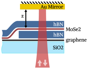
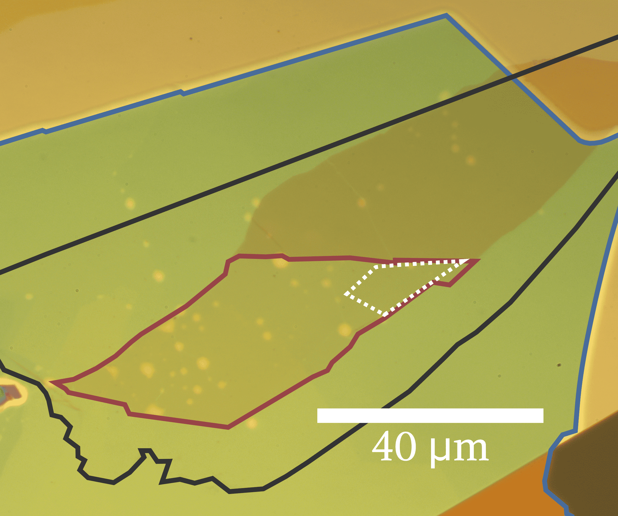
In the experiment we fabricate heterostructures of encapsulated in hBN, and then transfer these stacks onto fused silica substrates Zomer et al. (2014); Pizzocchero et al. (2016). A microscope image of the sample used for the data presented in this paper is shown in Fig. 1b, and a schematic of the experiment is shown in Fig. 1a. Experiments are conducted within an optical cryostat at 4 K. A gold mirror on a mechanical actuator is placed in close proximity to the heterostructure. The mirror is translated along the optical axis, and at selected positions reflectance measurements are made using a grating spectrometer. Note that is the optical path length between the mirror and the . This method of mirror translation isolates the effect of coherent electromagnetic feedback since it is entirely free of coupling to strain or electric field in the TMD. More detail on the samples and the experiment can be found in the methods sections I.1 and I.2. Because we excite with nW of continuous-wave optical power with a bandwidth of 300 nm the photon rate at the sample is GHz, and considering only optical power resonant with the rate is GHz. Taking into account the exciton decay rate of meV GHz, the excitation occupation number during the measurement is very low, .
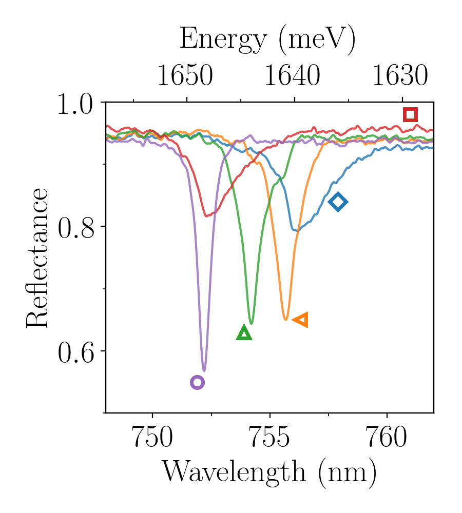
Maps of the magnitude of the dip in reflectance at and its center frequency/wavelength (, ) are shown in Fig. 1c. The mirror is near but not at maximum destructive interference. As observed by others Scuri et al. (2018); Cadiz et al. (2017), there is inhomogeneity on a few-micron scale in both and the magnitude of the reflection. Nonetheless, some areas of the sample are radiatively broadened. In Fig. 1d, spots are selected to show both a range of sample quality and .
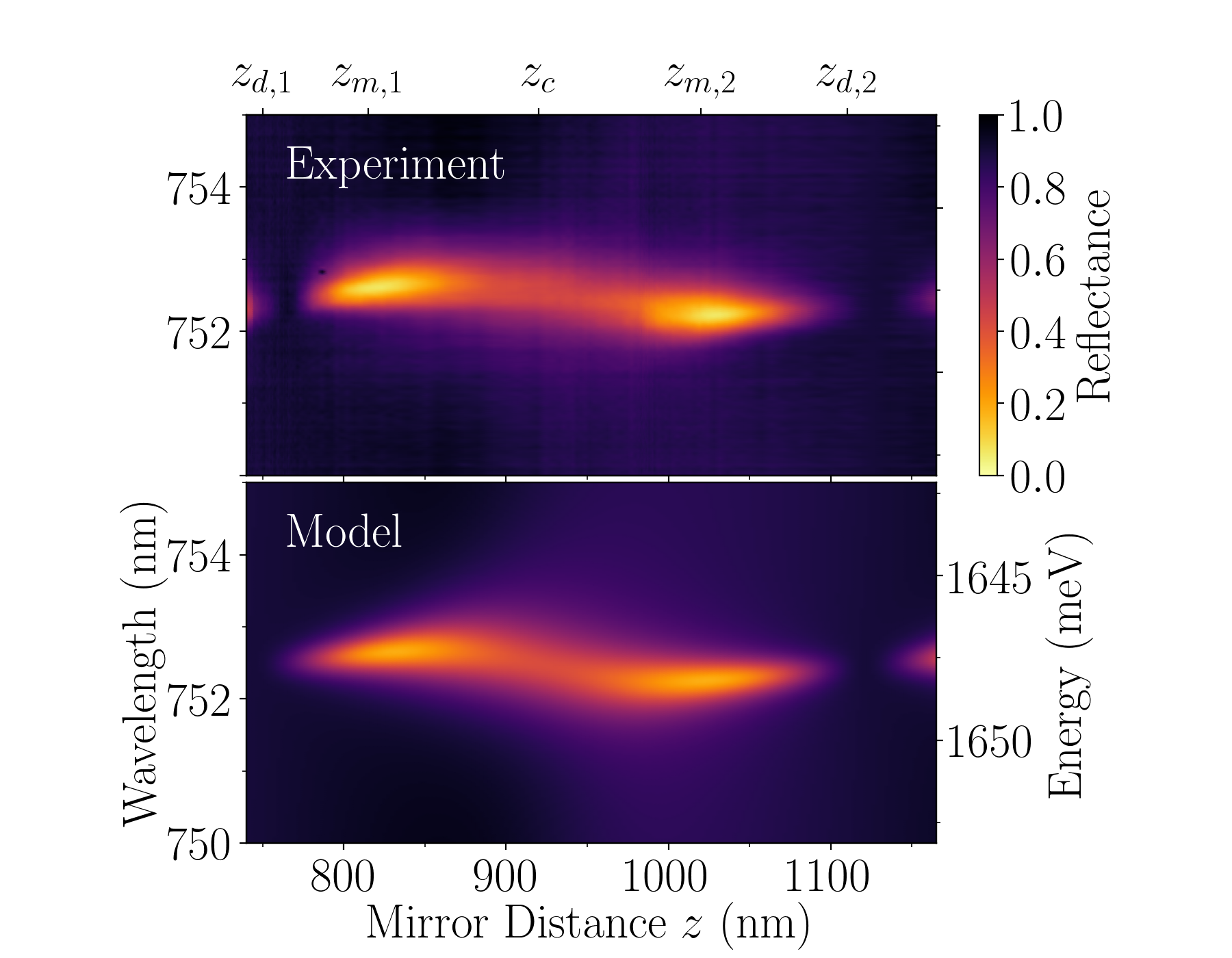
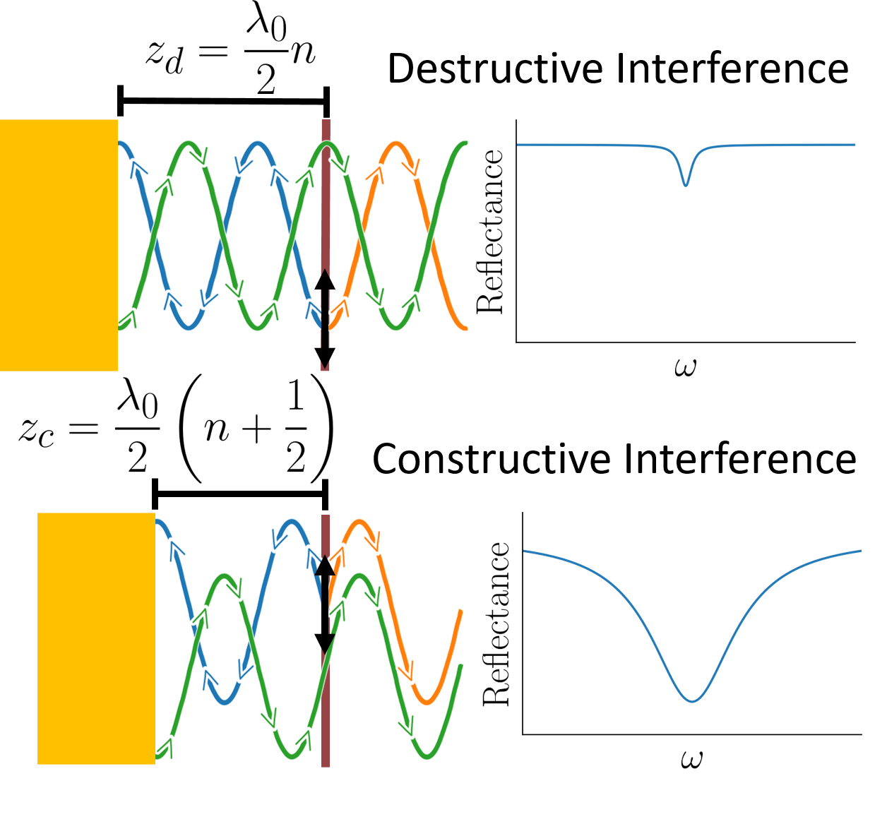
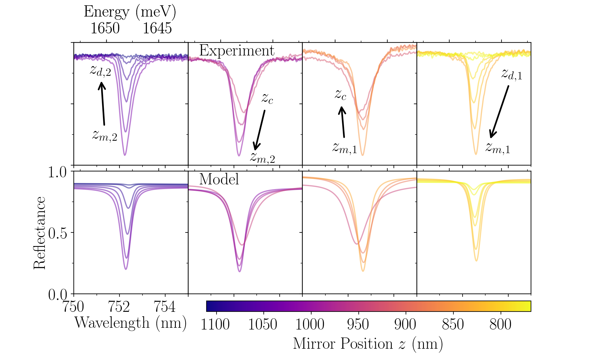

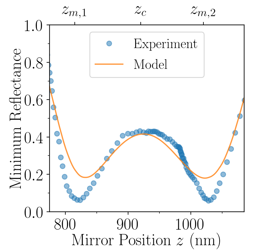
A heat map of the reflectance as a function of mirror position is shown in Fig. 2a, along with selected line cuts of the same data in Fig. 2c. The resonance appears as a dip (the central bright band) that varies in magnitude, width and center frequency as the mirror is translated across a full fringe. We define and as the mirror positions for maximal destructive and constructive interference respectively, as in Fig. 2b. When the reflection from the mirror interferes destructively with that from the , the radiative coupling of becomes very small and the dip disappears below the noise floor ( and in Fig. 2a). Surprisingly, the minimum reflection over does not occur at , but rather occurs at each of two mirror positions on either side of . At these two reflection minima ( nm and nm) the reflectance is , while in between it reaches at .
This surprising effect is due to an interplay between the radiative coupling rate () and non-radiative coupling rate (). At , the exciton is primarily radiatively broadened and is larger than , where is the effective contribution to the total linewidth from a Gaussian inhomogeneous broadening . We define as the total linewidth. In an ideal material () the reflectance would approach unity here. However, in our real sample and reduce the reflectance feature at to . When the mirror is moved in either direction from , and are reduced so that the exciton begins to absorb more light, causing the reflectance feature to deepen and eventually reach its minimum value at . It also begins to spectrally narrow, since the contribution of to the total linewidth is reduced. As the mirror is moved even farther away from past , continues to decrease and the feature shrinks while spectrally narrowing until it eventually disappears.
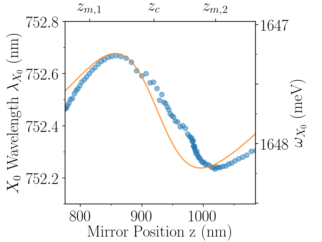
Note that the center frequency of the dip changes with mirror position as well. When the light reflected from the mirror is exactly in- or out-of-phase with that back-emitted from the , the dip is at its ‘vacuum’ frequency (), and . However, away from either of these positions dispersion over the resonance causes a spectrally asymmetric interference condition, which shifts the effective line center .
Plots of the modeled reflectance are shown in Figs. 2a and 2c. We model the TMD exciton using a Lorentzian susceptibility, shown in Eq. 1, which accounts for radiative broadening and non-radiative broadening Scuri et al. (2018); Wooten (1972). The reflectance is calculated for the full heterostructure and mirror using a transfer matrix method Katsidis and Siapkas (2002) including the effect of inhomogeneous broadening . Selected line cuts were simultaneously fit to the model to find global values for , , and . See the methods section I.3 for more details. Both qualitatively and quantitatively, the model matches closely with the experimental data. One slight difference is that the deepest reflectance feature obtained over is smaller in the experiment () than the model (), which is likely due to a combination of pure dephasing (which is not included in the model), spectrally structured inhomogeneous broadening, mode-mismatch between the interfering reflected beams, and diffraction effects. We attribute the slight discrepancy (distortion along ) between the model and experiment on the left in Fig. 2a to small imperfections in the calibration of the data.
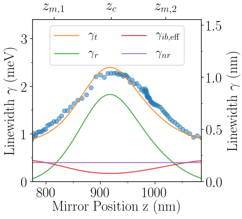
From both the experimental data and the model we extract full-width-half-max (FWHM) linewidths, which are shown in Fig. 3a. As a function of mirror position, the linewidth varies from meV near to meV at for a total modulation of , while in the model it varies from 0.9 to 2.4 meV, or . This modulation can also be clearly seen in Fig. 2d. The change in of the resonance is the primary cause of the change in , and the values of extracted from the model vary from near zero at to 1.8 meV (440 GHz) at . Near , is dominated by the contribution of and while at radiative coupling dominates, with a ratio of . Modeled and experimental values for and the minimum reflectance shown in Figs. 3b and 3c agree as well. The line shift of meV (240 GHz) is significant relative to .
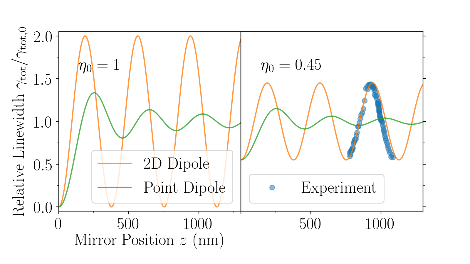
Lastly, in Fig. 3d we compare our data to a simplified model of both a 2D dipole and a point dipole. The 2D case highlights that the transverse coherence and delocalized nature of the exciton causes light emission into specific modes rather than the full numerical aperture. We define the coherent quantum efficiency in vacuum , which differs from the incoherent quantum efficiency . For our purpose, coherent quantum efficiency is the relevant quantity because the linewidth modulation effect depends on the coherent interference of emitted waves. Using models described in methods section I.4, we show that for an ideal 2D dipole () and a perfect planar mirror, the linewidth can be fully modulated even when the mirror is far from the dipole. This is not true in the 0D dipole case, because integrating emission over the full numerical aperture obscures the interference effect as increases. Also shown is a plot for chosen to match the superimposed experimental data. Note that the peak ratio extracted from the reflectance model does not match that of we expect for from this simplified model. This discrepancy is primarily due to varying with so as to partially counteract the change in , as seen in Fig. 3a. Because the intrinsically Lorentzian exciton feature is convolved with a Gaussian inhomogeneous broadening of width to form a Voight profile, the effective inhomogeneous broadening is larger when the total linewidth is small Liu et al. (2001); Olivero and Longbothum (1977). Regardless, the amplitude and phase of the experimental values highlight that no 0D dipole in front of a flat mirror (even with a perfect mirror and ) could produce the behavior seen in the experiments.
We have demonstrated coherent control over an exciton resonance by positioning a mirror in close proximity to the monolayer semiconductor , showing near complete modulation of the reflection at .
The concurrent change in radiative coupling rate induces a change in total linewidth of , demonstrating the dominant role of radiative coupling for excitons in monolayer and serving as an important verification of theoretical models used to describe excitonic physics in TMD materials.
For engineering applications, the modulation of the resonance could greatly enhance optomechanical couplings, while the effective enhancement of nonlinearities Wild et al. (2018) is useful for nonlinear optics and quantum optics.
Our strain free and DC electric field free method of mirror positioning has allowed us to study the underlying photonic interference effect present in the system, and the unprecedented control over the radiative coupling of an excitonic resonance paves the way for many future experiments.
Note: During preparation of this manuscript we became aware of a preprint presenting similar work by You Zhou, et. al. Zhou et al. (2019).
I Methods
I.1 Sample Preparation
We fabricate heterostructures like the one shown in Figs. 1a and 1b using a dry pickup transfer technique Zomer et al. (2014); Pizzocchero et al. (2016). First, hBN, and graphite are mechanically exfoliated Mak et al. (2010); Splendiani et al. (2010); Frindt (1965) onto 300 nm on Si substrates. The substrates are then observed under an optical microscope to identify suitable flakes. Polycarbonate (PC) ‘stamps’ are made by affixing a thin PC film to a piece of polydimethylsiloxane (PDMS) on a glass slide. This stamp is then used to sequentially pick up the mechanically exfoliated flakes by bringing the stamp slowly into contact with a flake on the exfoliation substrate. In our case, we first pick up the ‘top’ hBN, then the monolayer , then the ‘bottom’ hBN and finally the few-layer graphene flake. This stack (including the PC film) is transferred to a glass substrate. The PC is removed by dissolution in chloroform. Note that the protrudes from the bottom hBN so that it contacts the few-layer graphene flake, shorting the two to each other. This helps to electrostatically isolate the from the substrate. More details on sample preparation are given in the supplemental material.
The mirrors are prepared by taking a small glass substrate ( mm x 1 mm in lateral dimensions) and affixing it to a larger carrier substrate. This is then coated in 120 nm of gold, with a 3 nm titanium adhesion layer.
I.2 Experimental Setup
The experiment is conducted in an optical cryostat (Montana Instruments Nanoscale Workstation). All measurements were conducted at a nominal temperature of 4 K and a pressure of Torr. The sample is attached to a fixed mount. A gold mirror is mounted on a slip-stick piezo mirror mount (Janssen Precision Engineering) and brought close to the sample. The slip-stick piezo mirror mount is used to translate the mirror relative to the sample. A microscope objective (, 0.4 numerical aperture, Olympus MSPLAN) inside the cryostat was used to focus the beam onto the sample.
Light from either a lamp (Thorlabs SLS201) or a supercontinuum laser (NKT Photonics SuperK) is focused into a single mode optical fiber. This light is coupled into a home-built confocal microscope setup, which focuses the beam onto the sample. The collected reflected light is then sent to a home-built grating spectrometer for measurement. In order to translate the focus of the beam in three dimensions at the sample, the confocal microscope has a double 4f system. One tip-tilt mirror in the second 4f section translates the beam in the transverse plane, while a lens in the first 4f system is translated along the optical axis to move the beam focus along the optical axis. More details of the experimental setup can be found in the supplemental information. Each spectrum is normalized to a spectrum taken at a flake-free area on the substrate. Measurements were automated using the python instrument control package Instrumental Bogdanowicz et al. (2018), available on GitHub at https://github.com/mabuchilab/Instrumental.
I.3 Reflectance Model
For simplicity we use a classical model of stack reflectivity based on a Lorentzian susceptibility for the exciton, taking into account radiative broadening in vacuum and non-radiative broadening Wooten (1972); Scuri et al. (2018):
| (1) |
where is the exciton center frequency, is the optical frequency, is the speed of light, and is the thickness. The index of refraction of the is then:
| (2) |
where is the background index in the . Reflectance from the full stack including the mirror is calculated using a transfer-matrix-method to obtain Fresnel coefficients Katsidis and Siapkas (2002). Inhomogeneous broadening effects are included with a characteristic width of . To obtain the reflectance including inhomogeneous broadening, is calculated for a range of exciton center frequencies and combined by weighting with a Gaussian of width :
| (3) |
This assumes that the inhomogeneously broadened excitons emit incoherently, so that interference effects average out.
For fitting purposes, data from several line cuts at characteristic mirror positions were selected. The model was fit to all line cuts simultaneously, resulting in the following values for the free parameters: meV, meV, meV and meV. The mirror distance was also extracted from the spectra by fitting interference fringes at wavelengths far from . See the supplemental information for more details of both fitting procedures, and the values for the static parameters used in the reflectance model.
To extract the model parameters in Fig. 3a we first extract the total FWHM linewidth of the feature from the reflectance model as a function of mirror position . Assuming a Voight line shape Olivero and Longbothum (1977); Liu et al. (2001) we can extract the intrinsic Lorentzian linewidth () because the intrinsic Gaussian linewidth () is known directly from the model. This also yields the effective contribution to the linewidth of inhomogeneous broadening () as the difference between the total linewidth and the intrinsic Lorentzian linewidth. We can then trivially extract from the intrinsic Lorentzian linewidth because is known.
I.4 Simplified Linewidth Model
Simplified models for the linewidth modulation of 0D and 2D dipoles parallel to a perfect planar mirror were derived. The normalized total linewidth as a function of distance from the mirror is Drexhage (1970):
| (4) |
where is the total linewidth at normalized mirror position , is the total linewidth in vacuum and is the wavelength in vacuum. Following a similar procedure an equation for a 2D material was derived:
| (5) |
See the supplemental information for details of the derivation.
References
- Purcell et al. (1946) E. M. Purcell, H. C. Torrey, and R. V. Pound, “Resonance Absorption by Nuclear Magnetic Moments in a Solid,” Phys. Rev. 69, 37–38 (1946).
- Heinzen et al. (1987) D. J. Heinzen, J. J. Childs, J. E. Thomas, and M. S. Feld, “Enhanced and inhibited visible spontaneous emission by atoms in a confocal resonator,” Phys. Rev. Lett. 58, 1320–1323 (1987).
- Vredenberg et al. (1993) A. M. Vredenberg, N. E. J. Hunt, E. F. Schubert, D. C. Jacobson, J. M. Poate, and G. J. Zydzik, “Controlled atomic spontaneous emission from in a transparent Si/ microcavity,” Phys. Rev. Lett. 71, 517–520 (1993).
- Drexhage et al. (1968) K. H. Drexhage, H. Kuhn, and F. P. Schäfer, “Variation of the Fluorescence Decay Time of a Molecule in Front of a Mirror,” Berichte der Bunsengesellschaft für physikalische Chemie 72, 329–329 (1968).
- Drexhage (1970) K.H. Drexhage, “Influence of a dielectric interface on fluorescence decay time,” Journal of Luminescence 1-2, 693 – 701 (1970).
- Eschner et al. (2001) J. Eschner, Ch Raab, F. Schmidt-Kaler, and R. Blatt, “Light interference from single atoms and their mirror images,” Nature 413, 495 EP – (2001).
- Wilson et al. (2003) M. A. Wilson, P. Bushev, J. Eschner, F. Schmidt-Kaler, C. Becher, R. Blatt, and U. Dorner, “Vacuum-Field Level Shifts in a Single Trapped Ion Mediated by a Single Distant Mirror,” Phys. Rev. Lett. 91, 213602 (2003).
- Stobbe et al. (2009) S. Stobbe, J. Johansen, P. T. Kristensen, J. M. Hvam, and P. Lodahl, “Frequency dependence of the radiative decay rate of excitons in self-assembled quantum dots: Experiment and theory,” Phys. Rev. B 80, 155307 (2009).
- Cadiz et al. (2017) F. Cadiz, E. Courtade, C. Robert, G. Wang, Y. Shen, H. Cai, T. Taniguchi, K. Watanabe, H. Carrere, D. Lagarde, M. Manca, T. Amand, P. Renucci, S. Tongay, X. Marie, and B. Urbaszek, “Excitonic Linewidth Approaching the Homogeneous Limit in -Based van der Waals Heterostructures,” Phys. Rev. X 7, 021026 (2017).
- Scuri et al. (2018) Giovanni Scuri, You Zhou, Alexander A. High, Dominik S. Wild, Chi Shu, Kristiaan De Greve, Luis A. Jauregui, Takashi Taniguchi, Kenji Watanabe, Philip Kim, Mikhail D. Lukin, and Hongkun Park, “Large Excitonic Reflectivity of Monolayer Encapsulated in Hexagonal Boron Nitride,” Phys. Rev. Lett. 120, 037402 (2018).
- Back et al. (2018) Patrick Back, Sina Zeytinoglu, Aroosa Ijaz, Martin Kroner, and Atac Imamoğlu, “Realization of an Electrically Tunable Narrow-Bandwidth Atomically Thin Mirror Using Monolayer ,” Phys. Rev. Lett. 120, 037401 (2018).
- Meschede et al. (1990) D. Meschede, W. Jhe, and E. A. Hinds, “Radiative properties of atoms near a conducting plane: An old problem in a new light,” Phys. Rev. A 41, 1587–1596 (1990).
- Byrnes et al. (2014) Tim Byrnes, Na Young Kim, and Yoshihisa Yamamoto, “Exciton-polariton condensates,” Nature Physics 10, 803 EP – (2014), review Article.
- Zeytinoǧlu et al. (2017) Sina Zeytinoǧlu, Charlaine Roth, Sebastian Huber, and Atac İmamoğlu, “Atomically thin semiconductors as nonlinear mirrors,” Phys. Rev. A 96, 031801 (2017).
- Wild et al. (2018) Dominik S. Wild, Ephraim Shahmoon, Susanne F. Yelin, and Mikhail D. Lukin, “Quantum Nonlinear Optics in Atomically Thin Materials,” Phys. Rev. Lett. 121, 123606 (2018).
- Mak et al. (2010) Kin Fai Mak, Changgu Lee, James Hone, Jie Shan, and Tony F. Heinz, “Atomically Thin : A New Direct-Gap Semiconductor,” Phys. Rev. Lett. 105, 136805 (2010).
- Splendiani et al. (2010) Andrea Splendiani, Liang Sun, Yuanbo Zhang, Tianshu Li, Jonghwan Kim, Chi-Yung Chim, Giulia Galli, and Feng Wang, “Emerging Photoluminescence in Monolayer ,” Nano Letters 10, 1271–1275 (2010).
- Zhang et al. (2013) Yi Zhang, Tay-Rong Chang, Bo Zhou, Yong-Tao Cui, Hao Yan, Zhongkai Liu, Felix Schmitt, James Lee, Rob Moore, Yulin Chen, Hsin Lin, Horng-Tay Jeng, Sung-Kwan Mo, Zahid Hussain, Arun Bansil, and Zhi-Xun Shen, “Direct observation of the transition from indirect to direct bandgap in atomically thin epitaxial ,” Nature Nanotechnology 9, 111 EP – (2013).
- Molina-Sánchez et al. (2013) Alejandro Molina-Sánchez, Davide Sangalli, Kerstin Hummer, Andrea Marini, and Ludger Wirtz, “Effect of spin-orbit interaction on the optical spectra of single-layer, double-layer, and bulk MoS2,” Phys. Rev. B 88, 045412 (2013).
- Molina-Sánchez et al. (2016) Alejandro Molina-Sánchez, Maurizia Palummo, Andrea Marini, and Ludger Wirtz, “Temperature-dependent excitonic effects in the optical properties of single-layer ,” Phys. Rev. B 93, 155435 (2016).
- Jones et al. (2013) Aaron M. Jones, Hongyi Yu, Nirmal J. Ghimire, Sanfeng Wu, Grant Aivazian, Jason S. Ross, Bo Zhao, Jiaqiang Yan, David G. Mandrus, Di Xiao, Wang Yao, and Xiaodong Xu, “Optical generation of excitonic valley coherence in monolayer ,” Nature Nanotechnology 8, 634 EP – (2013).
- Xiao et al. (2012) Di Xiao, Gui-Bin Liu, Wanxiang Feng, Xiaodong Xu, and Wang Yao, “Coupled Spin and Valley Physics in Monolayers of and Other Group-VI Dichalcogenides,” Phys. Rev. Lett. 108, 196802 (2012).
- Mak et al. (2012a) Kin Fai Mak, Keliang He, Jie Shan, and Tony F. Heinz, “Control of valley polarization in monolayer by optical helicity,” Nature Nanotechnology 7, 494 EP – (2012a).
- Conley et al. (2013) Hiram J. Conley, Bin Wang, Jed I. Ziegler, Richard F. Haglund, Sokrates T. Pantelides, and Kirill I. Bolotin, “Bandgap Engineering of Strained Monolayer and Bilayer ,” Nano Letters 13, 3626–3630 (2013).
- You et al. (2015) Yumeng You, Xiao-Xiao Zhang, Timothy C. Berkelbach, Mark S. Hybertsen, David R. Reichman, and Tony F. Heinz, “Observation of biexcitons in monolayer ,” Nature Physics 11, 477 EP – (2015).
- Sidler et al. (2016) Meinrad Sidler, Patrick Back, Ovidiu Cotlet, Ajit Srivastava, Thomas Fink, Martin Kroner, Eugene Demler, and Atac Imamoglu, “Fermi polaron-polaritons in charge-tunable atomically thin semiconductors,” Nature Physics 13, 255 EP – (2016).
- Mak et al. (2012b) Kin Fai Mak, Keliang He, Changgu Lee, Gwan Hyoung Lee, James Hone, Tony F. Heinz, and Jie Shan, “Tightly bound trions in monolayer ,” Nature Materials 12, 207 EP – (2012b).
- Wang et al. (2018) Ke Wang, Kristiaan De Greve, Luis A. Jauregui, Andrey Sushko, Alexander High, You Zhou, Giovanni Scuri, Takashi Taniguchi, Kenji Watanabe, Mikhail D. Lukin, Hongkun Park, and Philip Kim, “Electrical control of charged carriers and excitons in atomically thin materials,” Nature Nanotechnology 13, 128–132 (2018).
- Palacios-Berraquero et al. (2017) Carmen Palacios-Berraquero, Dhiren M. Kara, Alejandro R. P Montblanch, Matteo Barbone, Pawel Latawiec, Duhee Yoon, Anna K. Ott, Marko Loncar, Andrea C. Ferrari, and Mete Atatüre, “Large-scale quantum-emitter arrays in atomically thin semiconductors,” Nature Communications 8, 15093 EP – (2017), article.
- Frindt (1965) R. F. Frindt, “Optical Absorption of a Few Unit-Cell Layers of Mo,” Phys. Rev. 140, A536–A539 (1965).
- Mennel et al. (2018) Lukas Mennel, Marco M. Furchi, Stefan Wachter, Matthias Paur, Dmitry K. Polyushkin, and Thomas Mueller, “Optical imaging of strain in two-dimensional crystals,” Nature Communications 9, 516 (2018).
- Hong et al. (2015) Jinhua Hong, Zhixin Hu, Matt Probert, Kun Li, Danhui Lv, Xinan Yang, Lin Gu, Nannan Mao, Qingliang Feng, Liming Xie, Jin Zhang, Dianzhong Wu, Zhiyong Zhang, Chuanhong Jin, Wei Ji, Xixiang Zhang, Jun Yuan, and Ze Zhang, “Exploring atomic defects in molybdenum disulphide monolayers,” Nature Communications 6, 6293 EP – (2015), article.
- Wang et al. (2015) Haining Wang, Changjian Zhang, and Farhan Rana, “Ultrafast Dynamics of Defect-Assisted Electron-Hole Recombination in Monolayer ,” Nano Letters 15, 339–345 (2015).
- Xue et al. (2011) Jiamin Xue, Javier Sanchez-Yamagishi, Danny Bulmash, Philippe Jacquod, Aparna Deshpande, K. Watanabe, T. Taniguchi, Pablo Jarillo-Herrero, and Brian J. LeRoy, “Scanning tunnelling microscopy and spectroscopy of ultra-flat graphene on hexagonal boron nitride,” Nature Materials 10, 282 EP – (2011).
- Brechbühler et al. (2018) Raphael Brechbühler, Freddy T. Rabouw, Patrik Rohner, Boris le Feber, Dimos Poulikakos, and David J. Norris, “Two-Dimensional Drexhage Experiment for Electric- and Magnetic-Dipole Sources on Plasmonic Interfaces,” Phys. Rev. Lett. 121, 113601 (2018).
- Langguth et al. (2016) Lutz Langguth, Romain Fleury, Andrea Alù, and A. Femius Koenderink, “Drexhage’s Experiment for Sound,” Phys. Rev. Lett. 116, 224301 (2016).
- Wang et al. (2016) Haining Wang, Changjian Zhang, Weimin Chan, Christina Manolatou, Sandip Tiwari, and Farhan Rana, “Radiative lifetimes of excitons and trions in monolayers of the metal dichalcogenide ,” Phys. Rev. B 93, 045407 (2016).
- Soh et al. (2018) Daniel B. S. Soh, Christopher Rogers, Dodd J. Gray, Eric Chatterjee, and Hideo Mabuchi, “Optical nonlinearities of excitons in monolayer ,” Phys. Rev. B 97, 165111 (2018).
- Yu et al. (2013) Yifei Yu, Chun Li, Yi Liu, Liqin Su, Yong Zhang, and Linyou Cao, “Controlled Scalable Synthesis of Uniform, High-Quality Monolayer and Few-layer Films,” Scientific Reports 3, 1866 EP – (2013), article.
- (40) Yi‐Hsien Lee, Xin‐Quan Zhang, Wenjing Zhang, Mu‐Tung Chang, Cheng‐Te Lin, Kai‐Di Chang, Ya‐Chu Yu, Jacob Tse‐Wei Wang, Chia‐Seng Chang, Lain‐Jong Li, and Tsung‐Wu Lin, “Synthesis of Large‐Area Atomic Layers with Chemical Vapor Deposition,” Advanced Materials 24, 2320–2325.
- Rogers et al. (2018) Christopher Rogers, Dodd Gray, Nate Bogdanowicz, and Hideo Mabuchi, “Laser annealing for radiatively broadened grown by chemical vapor deposition,” Phys. Rev. Materials 2, 094003 (2018).
- Zomer et al. (2014) P. J. Zomer, M. H. D. Guimarães, J. C. Brant, N. Tombros, and B. J. van Wees, “Fast pick up technique for high quality heterostructures of bilayer graphene and hexagonal boron nitride,” Applied Physics Letters 105, 013101 (2014).
- Pizzocchero et al. (2016) Filippo Pizzocchero, Lene Gammelgaard, Bjarke S. Jessen, José M. Caridad, Lei Wang, James Hone, Peter Bøggild, and Timothy J. Booth, “The hot pick-up technique for batch assembly of van der Waals heterostructures,” Nature Communications 7, 11894 EP – (2016), article.
- Wooten (1972) F. Wooten, Optical properties of solids (Academic Press, 1972) Chap. 3.
- Katsidis and Siapkas (2002) Charalambos C. Katsidis and Dimitrios I. Siapkas, “General transfer-matrix method for optical multilayer systems with coherent, partially coherent, and incoherent interference,” Appl. Opt. 41, 3978–3987 (2002).
- Liu et al. (2001) Yuyan Liu, Jieli Lin, Guangming Huang, Yuanqing Guo, and Chuanxi Duan, “Simple empirical analytical approximation to the Voigt profile,” J. Opt. Soc. Am. B 18, 666–672 (2001).
- Olivero and Longbothum (1977) J.J. Olivero and R.L. Longbothum, “Empirical fits to the Voigt line width: A brief review,” Journal of Quantitative Spectroscopy and Radiative Transfer 17, 233 – 236 (1977).
- Zhou et al. (2019) You Zhou, Giovanni Scuri, Jiho Sung, Ryan J. Gelly, Dominik S. Wild, Kristiaan De Greve, Andrew Y. Joe, Takashi Taniguchi, Kenji Watanabe, Philip Kim, Mikhail D. Lukin, and Hongkun Park, “Controlling excitons in an atomically thin membrane with a mirror,” arXiv e-prints , arXiv:1901.08500 (2019), arXiv:1901.08500 [cond-mat.mes-hall] .
- Bogdanowicz et al. (2018) Nate Bogdanowicz, Christopher Rogers, Dodd Gray, Chris Timossi, Francesco Marazzi, Jonathan Wheeler, and Ivan Galinskiy, “mabuchilab/Instrumental: 0.5,” (2018), 10.5281/zenodo.2556399.
II Additional Information
Supplementary Information is linked to the online version of the paper.
Acknowledgements.
This work was funded in part by the National Science Foundation (NSF) awards PHY-1648807 and DMR-1838497, and also by a seed grant from the Precourt Institute for Energy at Stanford University. Part of this work was performed at the Stanford Nano Shared Facilities (SNSF), supported by the NSF under award ECCS-1542152. C.R., D.G., and N.B. were supported in part by Stanford Graduate Fellowships. C.R. was also supported in part by a Natural Sciences and Engineering Research Council of Canada doctoral postgraduate scholarship. K.W. and T.T. acknowledge support from the Elemental Strategy Initiative conducted by the MEXT, Japan and and the CREST (JPMJCR15F3), JST. All authors thank Tatsuhiro Onodera for discussions relating to the reflectance model. All authors thank Daniel B. S. Soh and Eric Chatterjee for discussions relating to exciton physics. C.R. thanks Joe Finney, Giovanni Scuri and Elyse Barre for help with heterostructure fabrication, Logan Wright for pointing out relevant literature, and Peter L. McMahon for suggestions relating to the manuscript.III Author Contributions
C.R. conceived the experiments, fabricated the samples, performed the experiments, and performed the data analysis. C.R. and D.G. built the confocal microscope setup for the cryostat, as well as the grating spectrometer. C.R. and N.B. automated the measurements. T.T. and K.W. grew the hBN. C.R., N.B., D.G. and H.M. all contributed to the manuscript.
IV Competing financial interest
The authors declare no competing financial interests.
V Data availability
The data that support the findings of this study are available from the corresponding author upon reasonable request.