Photonic analogues of the Haldane and Kane-Mele models
Abstract
The condensed matter Haldane and Kane-Mele models revolutionized the understanding of what is an “insulator”, as they unveiled novel classes of media that behave as metals near the surface, but are insulating in the bulk. Here, we propose exact electromagnetic analogues of these two influential models relying on a photonic crystal implementation of “artificial graphene” subject to an effective magnetic field. For the Haldane model, the required effective magnetic field for photons can be emulated with a spatially variable pseudo-Tellegen response. For the Kane-Mele model, the spin-orbit coupling can be mimicked using matched anisotropic dielectrics with identical permittivity and permeability, without requiring any form of bianisotropic couplings. Using full wave numerical simulations and duality theory we verify that the nontrivial topology of the two proposed platforms results in the emergence of topologically protected gapless edge states at the interface with a trivial photonic insulator. Our theory paves the way for the emulation of the two condensed matter models in a photonic platform, and determines another paradigm to observe topologically protected edges-states in a fully reciprocal all-dielectric and non-uniform anisotropic metamaterial.
I Introduction
In recent years the advent of topological methods in electromagnetism brought new perspectives for robust waveguiding largely immune to fabrication imperfections lu_topological_2014 ; lu_topological_2016 ; Haldane_Nobel_2017 ; khanikaev_two-dimensional_2017 ; sun_two-dimensional_2017 ; ozawa_topological_2018 ; ma_guiding_2015 ; ma_scattering-free_2017 . Nontrivial photonic topological materials with a broken (non-broken) time-reversal symmetry were shown to enable unidirectional (bidirectional) and reflectionless edge state propagation at the interface with a trivial electromagnetic insulator. In addition to offering inherent optical isolation, these new paradigms to guide light without any backscattering may also have far-reaching repercussions in quantum optics barik_topological_2018 , in the realization of high-efficiency lasers harari_topological_2018 ; bandres_topological_2018 , or in light harvesting topological_sink_David .
Historically, the theory of topological photonics was largely inspired by its electronic counterpart raghu_analogs_2008 ; haldane_possible_2008 , i.e., by the properties of electronic phases of matter whose study started in the 1980s shortly after the discovery of the integer quantum Hall effect hasan_textitcolloquium_2010 ; shen_topological_2012 . In particular, two condensed-matter models played a major role in the development of this field: the Haldane model demonstrating that a broken time-reversal symmetry is the key ingredient to obtain a quantized Hall conductivity haldane_model_1988 , and the Kane-Mele model that showed that the spin-orbit coupling may imitate the effect of a magnetic field in time-reversal invariant electronic systems kane_quantum_2005 ; kane_$z_2$_2005 . Surprisingly, despite the many analogies drawn in the past years between electronic and photonic systems, there are no strict electromagnetic equivalents of the two models, and only a few first order approximations of the Kane-Mele model were identified in khanikaev_photonic_2013 ; slobozhanyuk_three-dimensional_2017 relying on bianisotropic materials with -coupling.
Here, building on a recent proposal for an electronic implementation of the Haldane model in “artificial graphene” made of a patterned 2D Electron Gas (2DEG) lannebere_link_2018 , we aim to fill this gap and propose exact analogues of the Haldane and Kane-Mele models in electromagnetics. To this end, in the first part of the article, we use an analogy between the Schrödinger and Maxwell equations to introduce a novel implementation of “photonic graphene” based on a honeycomb lattice of dielectric cylinders embedded in a metallic background. It is shown that the magnetic field of the Haldane model can be effectively implemented with a spatially varying pseudo-Tellegen coupling. In this manner, we construct an exact photonic analogue of the Haldane model. In the second part of the article, we demonstrate that by matching the electric and magnetic responses one obtains a precise analogue of the Kane-Mele model in the same nonreciprocal photonic platform. Next, it is shown that this nonreciprocal system can be linked through a duality transformation with another all-dielectric platform. Thereby, it follows that the Kane-Mele model can be implemented with a fully reciprocal metamaterial made of spatially dependent anisotropic dielectrics with no magnetoelectric coupling. Notably, the proposed system turns out to be parity-time-duality () symmetric silveirinha_PTD_2017 , a symmetry that guarantees bi-directional scattering-immune propagation under some conditions. Furthermore, our photonic implementation of the Kane-Mele model is also found to be related to the pseudo-magnetic field introduced by Liu and Li in liu_gauge_2015 . Thus, our analysis unveils a rather fundamental link between time-reversal invariant topological matter khanikaev_photonic_2013 , pseudo-magnetic fields liu_gauge_2015 and symmetric systems silveirinha_PTD_2017 ; chen_symmetry-protected_2015 .
II Electromagnetic Haldane model
The Haldane model is a condensed-matter model of a spinless electron that consists in the generalization of the tight-binding Hamiltonian of graphene to systems with a broken inversion symmetry (IS) and/or a broken time-reversal symmetry (TRS) haldane_model_1988 ; kim_realizing_2017 . In this model the topology of the bands –characterized by the electronic Chern number – is determined by the dominant broken symmetry: a dominant broken IS has a trivial topology with whereas a dominant broken TRS leads to a non-trivial topology with , and is characterized by the presence of unidirectional edge states protected against backscattering (a quantized Hall phase) at the interface with a trivial insulator. For more details about this model the reader is referred to haldane_model_1988 ; lannebere_link_2018 .
Here, we propose an electromagnetic equivalent of this condensed-matter system relying on an analogy between the 2D Schrödinger and Maxwell equations. The starting point of this analogy is the microscopic Schrödinger equation that emulates the Haldane model in artificial graphene lannebere_link_2018 , and whose main features are summarized in the next subsection.
II.1 Electronic Haldane model in a 2D Electron Gas
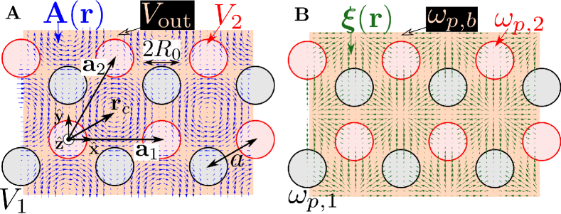
It was recently shown in lannebere_link_2018 that the Haldane model can be implemented in artificial graphene, i.e., an electronic platform that mimics the properties of graphene polini_artificial_2013 , for example a 2DEG under the influence of a periodic electrostatic potential with the honeycomb symmetry gibertini_engineering_2009 ; lannebere_effective_2015 ; wang_observation_2018 . As depicted in Figure 1A, a broken IS in artificial graphene can be realized with different potentials and in each sublattice, while a broken TRS can be obtained by applying a space-varying static magnetic field with zero spatial average. As proven in lannebere_link_2018 , a magnetic vector potential of the form
| (1) |
has the required symmetries to reproduce the Haldane model such that only the phase with dominant broken TRS leads to a non-trivial topology with . In the above formula is the distance between nearest sites (scattering centers) in the honeycomb lattice, is the peak magnetic field in Tesla, where determines the coordinates of the honeycomb cell’s center and the ’s with are the reciprocal lattice primitive vectors.
The electronic system of Figure 1A is characterized by a microscopic Hamiltonian
| (2) |
where is the electron effective mass, the momentum operator and is the elementary charge. It follows that the stationary states with energy i.e., the solutions of the time-independent Schrödinger’s equation , satisfy
| (3) |
Crucially, this microscopic equation with a magnetic vector potential given by Eq. (1) reproduces the symmetries of the Haldane model lannebere_link_2018 , and as shown next, can also be used to develop an analogy with the Maxwell equations.
II.2 Photonic analogue
The strategy adopted by us to obtain a photonic equivalent of the Haldane model (3) is to exploit a formal analogy between the 2D Schrödinger and Maxwell equations. For the sake of clarity, the analysis is divided into two steps: first it is shown how to create an electromagnetic equivalent of artificial graphene in a 2D photonic crystal. Then it is explained how to break the fundamental symmetries of the system in order to implement the electromagnetic Haldane model.
Using a six-vector formalism for the representation of the electromagnetic fields serdyukov_electromagnetics_2001 , the Maxwell equations with current-sources can be written in a compact manner as
| (4) |
where and stand for six-vectors whose components are the electric and magnetic fields and current densities respectively, and is the material matrix given by
| (5) |
where , , and are the relative permittivity, permeability and magnetoelectric tensors respectively. In addition, it is also assumed that the system is invariant to translations along the direction .
II.2.1 Photonic artificial graphene
During the last decade many photonic equivalents of graphene were put forward, notably relying on photonic crystals with either honeycomb or triangular symmetry with dielectric raghu_analogs_2008 ; sepkhanov_extremal_2007 ; peleg_conical_2007 ; ochiai_photonic_2009 ; zandbergen_experimental_2010 ; bravo-abad_enabling_2012 ; rechtsman_photonic_2013 ; plotnik_observation_2014 or metallic scatterers han_dirac_2009 ; bittner_observation_2010 ; bittner_extremal_2012 , or alternatively with semiconductor cavities jacqmin_direct_2014 . In the following, we suggest another approach to engineer “photonic graphene” based on a direct analogy between the 2D Schrödinger and Maxwell equations. To begin with, we consider a 2D non-magnetic photonic crystal described by the relative permittivity and permeability tensors
| (6) | ||||
| (7) |
In the absence of current-sources () the wave equation for transverse electric (TE) polarized waves () is given by Eq. (30) of the Appendix with . Supposing that the -component of the permittivity tensor is described by a Drude dispersion model, , the wave equation (30) reduces to
| (8) |
By comparing this formula with the Schrödinger equation of electronic artificial graphene, i.e., Eq. (3) in the absence of magnetic field (), it is seen that the solutions of both equations can be matched by taking
| (9) | ||||
| (10) |
In order that the analogy is perfect the plasma frequency of the material is required to be spatially dependent (a photonic crystal) with the same periodicity as the electronic potential. Incidentally it can be noted that because the right-hand side of (10) is always positive, this equivalence is only possible for a positive electric potential . However because only the difference is relevant in the Schrödinger equation (3), it is always feasible to transform a negative electric potential into a positive one by adding an overall constant potential to both and , such that the potential is transformed as and the origin of energy is shifted as . Thus, the relations (9) and (10) can always be satisfied when the electric potential has a lower bound. Then, following gibertini_engineering_2009 ; lannebere_effective_2015 ; wang_observation_2018 , we conclude that a strict photonic equivalent of artificial graphene can be implemented in a photonic crystal made of dielectric cylinders (“potential wells” with ) arranged in a honeycomb lattice in a metallic background (with ). To our best knowledge, this is the first proposal of a photonic equivalent of graphene based on a photonic crystal with a metallic background.
II.2.2 Magnetic field for photons with a spatially variable pseudo-Tellegen response
Now that we identified a photonic system with the same properties as graphene, the second step to emulate the Haldane model is to break the fundamental IS and TRS symmetries in this platform. In the electronic model (3) a broken IS is obtained by using different values of and in each sublattice of the honeycomb structure (Figure 1A). From the equivalence relation (10), the same effect may be attained in photonics by using scatterers with different plasma frequencies , in each sublattice, as depicted in Figure 1B.
On the other hand, a broken TRS is generally trickier to implement for photons. Here we create an effective magnetic field for photons by taking advantage of a bisanisotropic response of the medium. In particular, in addition to the effective permittivity (6) and permeability (7), it is assumed that the material response is nonreciprocal with a symmetric pseudo-Tellegen response (following the classification of serdyukov_electromagnetics_2001 ) with the magnetoelectric coupling tensors given by:
| (11) |
where is a generic vector lying in the plane. Notably as demonstrated in appendix A, such a magnetoelectric coupling does not mix the TE and TM polarizations. In particular, from (30) it follows that the wave equation for TE-polarized waves is:
| (12) |
By comparing this equation with the microscopic electronic Haldane model (3) it is seen that, in addition to the equivalence relations (9) and (10), the solutions of both equations can be matched by considering a spatially dependent pseudo-Tellegen response such that
| (13) |
Strikingly this relation proves that in two-dimensional scenarios a spatially varying pseudo-Tellegen response is the equivalent for photons of a magnetic field acting on electrons. Thus, it follows that Eq. (12) with a Tellegen-type coupling determined by (13) is the exact photonic counterpart of Eq. (3) and thereby yields a photonic Haldane model. Here, we note that Ref. jacobs_photonic_2015 studied a topological system with a similar Tellegen-coupling, but which is not an analogue of the Haldane model. Furthermore, Ref. he_photonic_2016 investigated a topological photonic crystal with an anti-symmetric moving-type nonreciprocal coupling serdyukov_electromagnetics_2001 ; kong_electromagnetic_2000 , which is different from the symmetric-Tellegen response considered by us.
By substituting the magnetic vector potential (1) into (13), the spatially dependent pseudo-Tellegen response is found to be given by
| (14) |
where is the dimensionless peak amplitude of the pseudo-Tellegen vector, which is linked to the parameters of the original electronic system as
| (15) |
For given values of and (corresponding to a specific implementation of the electronic Haldane model) the peak amplitude is -dependent. Importantly, the reality condition for the material matrix imposes that agranovich_crystal_1984 , a condition that is obviously violated by (15). For simplicity, we shall assume in this study that is frequency independent. A constant is equivalent to a nontrivial magnetic field whose strength is frequency dependent. Evidently, for positive frequencies the sign of is the same as the sign of , and hence the topological phases of the relevant photonic and electronic systems are strictly linked. Furthermore, provided Eq. (15) is satisfied for some frequency in the band gap, the physics of the two systems is essentially the same in the spectral region of the gap. Finally, we note that the proposed photonic platform emulates precisely the Haldane model even if the frequency dependence of does not follow (15). Indeed, independent of the dispersion of , in a tight-binding binding approximation the system is rigorously described by Haldane’s theory.
In summary, it was demonstrated that a bianisotropic metamaterial characterized by effective parameters of the form (6), (7), (11) and such that is given by a Drude model and by equation (14) yields an analogue of the Haldane model for photons. The phase diagram relating the photonic gap Chern number to the strength of the pseudo-Tellegen response and to the asymmetry of the sub-lattices (measured by ) can be found from the corresponding electronic phase diagram (Figure 1(d) of lannebere_link_2018 ) using the relations (9), (10), (13) and (15).
II.3 Numerical examples
To illustrate the ideas developed so far, next we present the band diagrams and the typical field profiles associated with each topological phase of the photonic Haldane model. All the simulations presented here were numerically obtained with a dedicated finite-differences frequency-domain method (FDFD) whose details can be found in lannebere_effective_2015 .
The electromagnetic system is constructed from a dual electronic system through the equivalence relations (9), (10) and (13). We choose the original electronic platform as the patterned 2DEG of Figure 1A with parameters , , , and , with the electron rest mass. With such parameters the electronic system behaves as graphene near the normalized energy where its band diagram consists of two Dirac cones centered at the high-symmetry and points. For the system reduces to the artificial graphene studied in lannebere_link_2018 ; lannebere_effective_2015 after adding a constant potential to the whole structure to guarantee that .
The direct application of the equivalence relations (9), (10) to the artificial graphene leads to a simple photonic crystal made of air cylinders () embedded in a metal with a Drude dispersion. The band diagram of the photonic crystal close to the Dirac point is depicted in Figure 2A as a function of the wavevector taken relatively to the point.
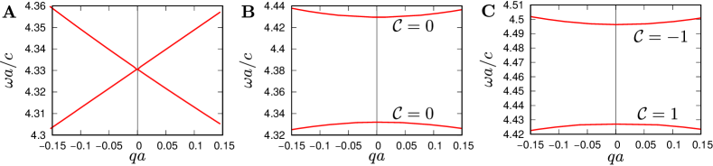
As expected, the frequency dispersion is approximately a linear function of forming a Dirac cone at and (not shown), thus validating that the proposed structure is a photonic equivalent of graphene. As seen in Figures 2B and C, by breaking either the IS () or the TRS () it is possible to open a band-gap in the band diagram. Moreover, similar to the electronic Haldane model, the phases induced by each of the broken symmetries are topologically distinct, as expressed by the different values of the photonic Chern number . Specifically, for the phase with broken IS whereas for the phase with broken TRS. It should be noted that with a frequency independent and with the properties of the photonic system are fully scalable with frequency, and the exact gap spectral range is determined only by .
According to the bulk-edge correspondence lu_topological_2014 ; raghu_analogs_2008 ; silveirinha_proof_2018 the difference in the Chern numbers should manifest itself directly on the propagation of the edge states at the interface with a trivial photonic insulator. In particular, it is expected that the phase with broken TRS symmetry supports unidirectional edge states protected against backscattering with a dispersion that spans the entire band-gap. To confirm this property the solutions of the wave equation in the closed cavity of Figure 3A,
| (16) |
were computed with the FDFD method lannebere_effective_2015 with the wave excited by a point-like electric current distribution . The cavity walls were chosen to be perfect electric conductors (PEC), i.e., the Haldane photonic crystal is surrounded by a trivial insulator. The oscillation frequency of the current source is centered in the band-gap. To ease the field visualization in the closed cavity, an absorber was placed at the right-bottom part of the structure. The absorption is stronger near the center (darker colors in Figure 3A imply a stronger absorption).
The excited field profiles for the distinct topological phases of photonic Haldane graphene are represented in Figure 3B–E.
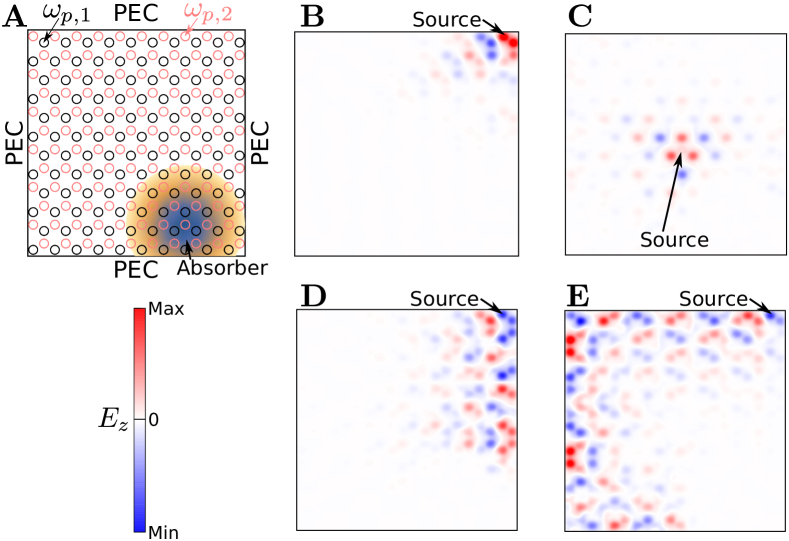
As seen in Figure 3B, the phase characterized by a broken IS does not support any bulk or unidirectional edge mode at this frequency, confirming that this phase is topologically trivial. The absence of bulk modes for the phase with a broken TRS is also verified in Figure 3C, which reveals that for an excitation far from the edges, the fields decay rapidly with the distance to the source.
The situation is dramatically different for sources positioned near the boundaries. Figures 3D and E show that in such a case an unidirectional edge state with propagation direction locked to the sign of is excited near the PEC walls. Crucially, the topologically protected modes do not experience any backscattering at the corners of the cavity.
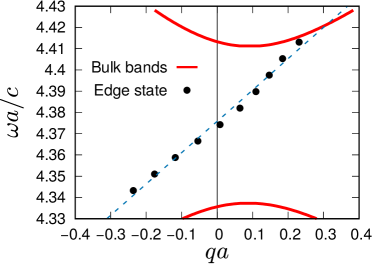
The edge mode dispersion in the band-gap region was found by numerically fitting the spatial variation of the edge waves to that of a Bloch wave. As depicted in Figure 4, the edge mode dispersion is approximately linear and for the edge wave propagating attached to the top interface it is centered about the point and spans the entire band gap. The gap Chern number –given by the sum of the Chern numbers of the bands below the gap, including the negative frequency bands– is for the phase with a dominant broken TRS. In agreement with the results of silveirinha_quantized_2019 ; silveirinha_proof_2018 the gap Chern number is positive (negative) for an energy flow in the clockwise (anticlockwise) direction. The electric field time animations of the examples of Figure 3D and E are available in the Supplementary Material.
It is relevant to mention that because of computational restrictions the maximum number of mesh cells allowed by our numerical code is limited. For this reason the results of Figures 3 and 4 – for a computational domain formed by many cells – were obtained with a relatively low mesh density. For consistency, the band structure shown in Fig. 4 was calculated using the same mesh as the one used to obtain the edge states dispersion. The coarser mesh leads to a slight numerical shift with respect to the more exact band structure results of Figure 2.
Also because of computational limitations, the calculation of the edge modes dispersion is challenging when they are weakly confined to the cavity walls. To obtain the most accurate results, we focused on a phase with a broken TRS, but with a preserved inversion symmetry () to maximize the bandgap width. Indeed, the edge state confinement is stronger for a larger gap energy. We numerically verified that as long as TRS remains the dominant broken symmetry the introduction of a broken IS () does not affect the topological properties of the system, and the presence of gapless edge states.
III Photonic Kane-Mele model
The electronic Kane-Mele model was introduced around 2005 in a series of two papers kane_quantum_2005 ; kane_$z_2$_2005 . It describes a time-reversal invariant mechanism that effectively imitates the effect of a magnetic field for each electron spin. The Kane-Mele model is also based on the tight-binding Hamiltonian of graphene but with the two different spins coupled by the spin-orbit interaction. The most remarkable prediction of this model is that the spin-orbit coupling can induce topologically nontrivial band gaps characterized by the presence of scattering-immune spin-polarized edge currents, a phenomenon known as the quantum spin Hall effect. This effect was first experimentally observed in HgCdTe quantum wells konig_quantum_2007 . Recently, photonic analogues of such non-trivial electronic edge states were studied in several electromagnetic systems with the spin degree of freedom mimicked by the light polarization and the spin-orbit coupling by, for example, a bianisotropic coupling khanikaev_photonic_2013 ; slobozhanyuk_three-dimensional_2017 or by particular symmetries of the waveguide silveirinha_PTD_2017 ; chen_symmetry-protected_2015 ; martini_exact_2019 .
Mathematically, the Kane-Mele model can be as well regarded as two copies of the Haldane model with each electron spin experiencing an opposite magnetic field shen_topological_2012 ; kane_$z_2$_2005 . By adopting this point of view and building on the results of the previous section, we show in Sect. III.1 how to mimic the Kane-Mele model with a nonreciprocal photonic platform with a pseudo-Tellegen response. We establish a link between this platform and the class of -invariant systems, i.e., systems invariant under the composition of the parity , time-reversal , and duality transformations silveirinha_PTD_2017 . Finally, in Sect. III.2 using duality theory we propose an alternative implementation of the Kane-Mele model in a fully reciprocal platform made of anisotropic dielectrics.
III.1 Kane-Mele model in a nonreciprocal system
We consider here the photonic crystal of Figure 1B, with the same relative permittivity (6) and magnetoelectric tensors (11) as in Section II, but with matched permittivity and permeability tensors:
| (17) | ||||
| (18) |
As in Section II, it is assumed that are space independent and that the component of the permittivity and permeability tensors are given by a Drude model in the frequency range of interest. From Eqs.(30) and (31) of the appendix, the wave equations for transverse electric (TE) () and transverse magnetic (TM) () polarized waves are
| (19a) | ||||
| (19b) | ||||
Remarkably, even though the two polarizations are uncoupled, the wave propagation of TE and TM waves is ruled essentially by the same equation, except for the pseudo-Tellegen vector which has an opposite orientation for TE and TM waves. Here, only plays the role of a normalization factor and can without loss of generality be taken equal to unity. In this case and for given by Eq. (14), the wave equations (19) reduce to two copies of the photonic Haldane model (12) with an opposite orientation of the pseudo-Tellegen vector. By virtue of Eq. (13), this situation corresponds in the electronic case to two copies of the Haldane model with opposite magnetic fields, which is precisely the Kane-Mele model kane_quantum_2005 ; kane_$z_2$_2005 . Hence, Eqs. (19) yield a strict photonic analogue of the Kane-Mele model with the spin-orbit coupling mimicked by the nonreciprocal pseudo-Tellegen response. From Sect. II, it is clear that the pseudo-Tellegen coupling opens a topologically non-trivial band-gap wherein TE and TM polarized edge states can propagate in opposite directions without back reflections at the interface with a trivial photonic insulator.
Interestingly, it can be readily checked that a photonic platform with effective parameters that satisfy (17)–(18) is -invariant silveirinha_PTD_2017 . The scattering phenomena in -invariant systems is characterized by an anti-symmetric scattering matrix, and this property guarantees that a generic -invariant microwave network is matched at all ports silveirinha_PTD_2017 ; martini_exact_2019 . In particular, any -invariant waveguide that supports a single propagating mode (for fixed direction of propagation) is completely immune to back-reflections silveirinha_PTD_2017 . Note that -invariant systems are always bidirectional. Thus, the absence of backscattering in the proposed photonic Kane-Mele model can also be explained as a consequence of -invariance.
III.2 Kane-Mele model in a reciprocal system
While the ideas developed in the last section are interesting from a theoretical standpoint, their impact on more practical grounds is admittedly limited, mainly because of the difficulty to obtain a pseudo-Tellegen response astrov_magnetoelectric_1961 . Next, we show that the nonreciprocal -invariant platform studied in Section III.1 can be transformed into an equivalent fully reciprocal non-bianisotropic system by means of a duality transformation silveirinha_PTD_2017 .
The key observation is that a duality transformation acts exclusively on the fields, leaving the space and time unaffected silveirinha_PTD_2017 ; prudencio_geometrical_2014 ; prudencio_optical_2016 . Thereby, the wave phenomena and topological properties of two systems linked by a duality transformation are fundamentally the same. In particular a duality transformation preserves the band diagram dispersion and the immunity to back-scattering silveirinha_PTD_2017 ; prudencio_asymmetric_2015 ; prudencio_geometrical_2014 .
As in silveirinha_PTD_2017 , we consider a duality transformation of the form
| (20) |
where is the free space impedance. The duality transformation changes the material parameters as silveirinha_PTD_2017 . For a bianisotropic material with matched permittivity and permeability and matched magnetoelectric couplings , it leads to a new material described by
| (21) |
Notably the new material has no magnetoelectric coupling, and for symmetric and tensors the response is reciprocal. If the parameters of the original material are given by (17)-(18), then the permittivity and permeability tensors of the new material are explicitly:
| (22a) | ||||
| (22b) | ||||
Interestingly, it can be readily verified that a system described by the tensors and satisfies Eq. (12) of silveirinha_PTD_2017 implying that it is -invariant. This further confirms that the proposed platform can support scattering-immune edge modes. Furthermore, the tensors and are symmetric indicating that the transformed system is as well reciprocal.
The tensors and have the same diagonal part whereas their out-of-diagonal elements have opposite signs. Clearly, the duality transformation preserves the diagonal elements of the permittivity and permeability whereas the pseudo-Tellegen response of the original material becomes the out-of-diagonal part of and . Evidently, the out-of-diagonal parameters play the role of an effective magnetic field for photons and are responsible for the bidirectional and reflectionless edge wave propagation in this structure. Interestingly, Liu and Li have previously shown using totally different physical arguments that spatially dependent anisotropic media with a structure analogous to (22) can be used to create a pseudomagnetic field for photons liu_gauge_2015 ; liu_polarization-dependent_2015 ; liu_invisibility_2017 . Thus, our theory merges the concepts of pseudomagnetic fields and time-reversal invariant topological matter as particular cases of the broader class of -invariant systems silveirinha_PTD_2017 .
It is highlighted that the wave propagation in a structure described by the parameters (22) is fully determined by the wave propagation in the two associated copies of the photonic Haldane model. Thereby, similar to Sec. II.3, the material characterized by (22) supports topologically protected (but bidirectional) edge states. The cavity walls should enforce the (-invariant) mixed boundary conditions and . These “soft” boundary conditions were originally studied by Kildal and can be implemented with corrugated surfaces kildal_artificially_1990 . The solution of the outlined cavity problem may be strictly related through the duality transformation (20) with the numerical simulations of Sec. II.3.
In conclusion, we proposed a fully reciprocal -invariant photonic platform based on non-uniform anisotropic dielectrics that supports bidirectional edge mode propagation protected against back-reflections. Importantly, the concept of -invariance is a single-frequency condition, and thereby it is sufficient that the material parameters satisfy Eqs.(22) in some frequency in the band-gap to observe the scattering-immune bidirectional edge state propagation. This property let us hope that even though challenging a practical implementation of the proposed metamaterials with spatially dependent parameters may be feasible in the future.
IV Conclusions
We used an analogy between the 2D Schrödinger and Maxwell equations to obtain an electromagnetic equivalent of the electronic Haldane and Kane-Mele models. First, we introduced a novel realization of photonic graphene based on a photonic crystal formed by dielectric cylinders arranged in a honeycomb lattice and embedded in a metallic host with a Drude-type dispersion. Then, it was shown that a spatially varying pseudo-Tellegen coupling is the photonic equivalent of a magnetic field acting on electrons. Using this result, we proposed an exact electromagnetic analogue of the Haldane model.
Furthermore, by imposing that the permittivity and the permeability are matched, it is possible to create two copies of the photonic Haldane model in the same physical platform, and in this manner implement the Kane-Mele model. Interestingly, this nonreciprocal platform is related through a duality transformation with a much simpler reciprocal system with the same edge states. Thereby, our analysis proves that the Kane-Mele model can be rigorously implemented using matched non-bianisotropic dielectrics and that such structures can support bi-directional edge states immune to back-scattering. The link between this system and -invariant materials was established. Furthermore, it was highlighted that all the known mechanisms that enable the propagation of light in reciprocal structures with no back-scattering, e.g., relying on pseudomagnetic fields or time-reversal invariant topological insulators, fall under the umbrella of -invariant systems.
Acknowledgement
This work was partially funded by the IET under the A F Harvey Engineering Prize, by Fundação para a Ciência e a Tecnologia under projects PTDC/EEI-TEL/4543/2014 and DL 57/2016/CP1353/CT0001 and by Instituto de Telecomunicações under project UID/EEA/50008/2017.
Appendix A Wave-equation in a pseudo-Tellegen medium
We consider a nonreciprocal material described by the tensors serdyukov_electromagnetics_2001 :
| (23) | ||||
| (24) | ||||
| (25) |
The symmetric magnetoelectric coupling tensors determine a nonreciprocal pseudo-Tellegen response. Here , , , are the parallel (in plane) and perpendicular (out of plane) components of the relative permittivity and permeability respectively, and is a vector lying in the plane.
In the absence of current-sources and for a time-harmonic variation of the form , the Maxwell equations (4) in this system reduce to
| (26) | |||
| (27) |
Remarkably, for a medium invariant to translations along the -direction () the pseudo-Tellegen magnetoelectric coupling considered here does not mix the polarizations, i.e, the decomposition into TE () and TM () waves is valid. Then (26) and (27) lead to the two following independent equations for TE and TM waves
| (28) | ||||
| (29) |
The above equations can be further simplified if one also assumes that the parallel components of the permittivity or permeability are space independent, leading to the following uncoupled wave equations for TE and TM waves respectively
| (30) | ||||
| (31) |
References
- (1) Lu, L., Joannopoulos, J. D. & Soljačić, M. Topological photonics. Nat. Photonics 8, 821–829 (2014).
- (2) Lu, L., Joannopoulos, J. D. & Soljačić, M. Topological states in photonic systems. Nat. Phys. 12, 626–629 (2016).
- (3) Haldane, F. D. M. Nobel lecture: Topological quantum matter. Rev. Mod. Phys. 89, 040502 (2017).
- (4) Khanikaev, A. B. & Shvets, G. Two-dimensional topological photonics. Nature Photonics 11, 763–773 (2017).
- (5) Sun, X.-C. et al. Two-dimensional topological photonic systems. Progress in Quantum Electronics 55, 52–73 (2017).
- (6) Ozawa, T. et al. Topological Photonics. arXiv:1802.04173 (2018).
- (7) Ma, T., Khanikaev, A. B., Mousavi, S. H. & Shvets, G. Guiding Electromagnetic Waves around Sharp Corners: Topologically Protected Photonic Transport in Metawaveguides. Phys. Rev. Lett. 114, 127401 (2015).
- (8) Ma, T. & Shvets, G. Scattering-free edge states between heterogeneous photonic topological insulators. Phys. Rev. B 95, 165102 (2017).
- (9) Barik, S. et al. A topological quantum optics interface. Science 359, 666–668 (2018).
- (10) Harari, G. et al. Topological insulator laser: Theory. Science 359, eaar4003 (2018).
- (11) Bandres, M. A. et al. Topological insulator laser: Experiments. Science eaar4005 (2018).
- (12) Fernandes, D. E. & Silveirinha, M. G. Topological energy sink (2018).
- (13) Raghu, S. & Haldane, F. D. M. Analogs of quantum-Hall-effect edge states in photonic crystals. Phys. Rev. A 78, 033834 (2008).
- (14) Haldane, F. D. M. & Raghu, S. Possible Realization of Directional Optical Waveguides in Photonic Crystals with Broken Time-Reversal Symmetry. Phys. Rev. Lett. 100, 013904 (2008).
- (15) Hasan, M. Z. & Kane, C. L. Colloquium : Topological insulators. Rev. Mod. Phys. 82, 3045–3067 (2010).
- (16) Shen, S.-Q. Topological Insulators, vol. 174 of Springer Series in Solid-State Sciences (Springer, Berlin, Heidelberg, 2012).
- (17) Haldane, F. D. M. Model for a Quantum Hall Effect without Landau Levels: Condensed-Matter Realization of the ”Parity Anomaly”. Phys. Rev. Lett. 61, 2015–2018 (1988).
- (18) Kane, C. L. & Mele, E. J. Quantum Spin Hall Effect in Graphene. Phys. Rev. Lett. 95, 226801 (2005).
- (19) Kane, C. L. & Mele, E. J. Topological Order and the Quantum Spin Hall Effect. Phys. Rev. Lett. 95, 146802 (2005).
- (20) Khanikaev, A. B. et al. Photonic topological insulators. Nat. Mat. 12, 233–239 (2013).
- (21) Slobozhanyuk, A. et al. Three-dimensional all-dielectric photonic topological insulator. Nat. Photonics 11, 130–136 (2017).
- (22) Lannebère, S. & Silveirinha, M. G. Link between the photonic and electronic topological phases in artificial graphene. Phys. Rev. B 97, 165128 (2018).
- (23) Silveirinha, M. G. symmetry-protected scattering anomaly in optics. Phys. Rev. B 95, 035153 (2017).
- (24) Liu, F. & Li, J. Gauge Field Optics with Anisotropic Media. Phys. Rev. Lett. 114, 103902 (2015).
- (25) Chen, W.-J., Zhang, Z.-Q., Dong, J.-W. & Chan, C. T. Symmetry-protected transport in a pseudospin-polarized waveguide. Nat. Commun. 6, 8183 (2015).
- (26) Kim, H.-S. & Kee, H.-Y. Realizing Haldane model in Fe-based honeycomb ferromagnetic insulators. npj Quantum Materials 2, 20 (2017).
- (27) Polini, M., Guinea, F., Lewenstein, M., Manoharan, H. C. & Pellegrini, V. Artificial honeycomb lattices for electrons, atoms and photons. Nature Nanotechnology 8, 625–633 (2013).
- (28) Gibertini, M. et al. Engineering artificial graphene in a two-dimensional electron gas. Phys. Rev. B 79, 241406 (2009).
- (29) Lannebère, S. & Silveirinha, M. G. Effective Hamiltonian for electron waves in artificial graphene: A first-principles derivation. Phys. Rev. B 91, 045416 (2015).
- (30) Wang, S. et al. Observation of Dirac bands in artificial graphene in small-period nanopatterned GaAs quantum wells. Nature Nanotechnology 13, 29–33 (2018).
- (31) Serdyukov, A., Semchenko, I., Tretyakov, S. & Sihvola, A. Electromagnetics of bi-anisotropic materials: Theory and applications (2001).
- (32) Sepkhanov, R. A., Bazaliy, Y. B. & Beenakker, C. W. J. Extremal transmission at the Dirac point of a photonic band structure. Phys. Rev. A 75, 063813 (2007).
- (33) Peleg, O. et al. Conical Diffraction and Gap Solitons in Honeycomb Photonic Lattices. Phys. Rev. Lett. 98, 103901 (2007).
- (34) Ochiai, T. & Onoda, M. Photonic analog of graphene model and its extension: Dirac cone, symmetry, and edge states. Phys. Rev. B 80, 155103 (2009).
- (35) Zandbergen, S. R. & de Dood, M. J. A. Experimental Observation of Strong Edge Effects on the Pseudodiffusive Transport of Light in Photonic Graphene. Phys. Rev. Lett. 104, 043903 (2010).
- (36) Bravo-Abad, J., Joannopoulos, J. D. & Soljačić, M. Enabling single-mode behavior over large areas with photonic Dirac cones. PNAS 109, 9761–9765 (2012).
- (37) Rechtsman, M. C. et al. Photonic Floquet topological insulators. Nature 496, 196–200 (2013).
- (38) Plotnik, Y. et al. Observation of unconventional edge states in ‘photonic graphene’. Nature Materials 13, 57–62 (2014).
- (39) Han, D., Lai, Y., Zi, J., Zhang, Z.-Q. & Chan, C. T. Dirac Spectra and Edge States in Honeycomb Plasmonic Lattices. Phys. Rev. Lett. 102, 123904 (2009).
- (40) Bittner, S. et al. Observation of a Dirac point in microwave experiments with a photonic crystal modeling graphene. Phys. Rev. B 82, 014301 (2010).
- (41) Bittner, S., Dietz, B., Miski-Oglu, M. & Richter, A. Extremal transmission through a microwave photonic crystal and the observation of edge states in a rectangular Dirac billiard. Phys. Rev. B 85, 064301 (2012).
- (42) Jacqmin, T. et al. Direct Observation of Dirac Cones and a Flatband in a Honeycomb Lattice for Polaritons. Phys. Rev. Lett. 112, 116402 (2014).
- (43) Jacobs, D. A., Miroshnichenko, A. E., Kivshar, Y. S. & Khanikaev, A. B. Photonic topological Chern insulators based on Tellegen metacrystals. New J. Phys. 17, 125015 (2015).
- (44) He, C. et al. Photonic topological insulator with broken time-reversal symmetry. Proceedings of the National Academy of Sciences 113, 4924–4928 (2016).
- (45) Kong, J. A. Electromagnetic Wave Theory (E M W Pub, Cambridge, MA, 2000).
- (46) Agranovich, V. M. & Ginzburg, V. Crystal Optics with Spatial Dispersion, and Excitons, vol. 42 of Springer Series in Solid-State Sciences (Springer Berlin Heidelberg, Berlin, Heidelberg, 1984).
- (47) Silveirinha, M. G. Proof of the bulk-edge correspondence through a link between topological photonics and fluctuation-electrodynamics. Phys. Rev. X (in press) (2019).
- (48) Silveirinha, M. G. Quantized angular momentum in topological optical systems. Nature Communications 10, 349 (2019).
- (49) König, M. et al. Quantum Spin Hall Insulator State in HgTe Quantum Wells. Science 318, 766–770 (2007).
- (50) Martini, E., Silveirinha, M. G. & Maci, S. Exact Solution for the Protected TEM Edge Mode in a PTD-Symmetric Parallel-Plate Waveguide. IEEE Trans. Antennas and Propag. 67, 1035–1044 (2019).
- (51) Astrov, D. N. Magnetoelectric effect in chromium oxide. Sov. Phys. JETP 13, 729–733 (1961).
- (52) Prudêncio, F. R., Matos, S. A. & Paiva, C. R. A Geometrical Approach to Duality Transformations for Tellegen Media. IEEE Trans. Microw. Theory and Tech. 62, 1417–1428 (2014).
- (53) Prudêncio, F. R. & Silveirinha, M. G. Optical isolation of circularly polarized light with a spontaneous magnetoelectric effect. Phys. Rev. A 93, 043846 (2016).
- (54) Prudêncio, F. R., Matos, S. A. & Paiva, C. R. Asymmetric band diagrams in photonic crystals with a spontaneous nonreciprocal response. Phys. Rev. A 91, 063821 (2015).
- (55) Liu, F., Wang, S., Xiao, S., Hang, Z. H. & Li, J. Polarization-dependent optics using gauge-field metamaterials. Appl. Phys. Lett. 107, 241106 (2015).
- (56) Liu, F., Horsley, S. A. R. & Li, J. Invisibility cloaking using pseudomagnetic field for photon. Phys. Rev. B 95, 075157 (2017).
- (57) Kildal, P. Artificially soft and hard surfaces in electromagnetics. IEEE Trans. Antennas and Propag. 38, 1537–1544 (1990).