Reduction of coherent betatron oscillations in a muon g-2 storage ring experiment using RF fields
Abstract
This work demonstrates that two systematic errors, coherent betatron oscillations (CBO) and muon losses can be reduced through application of radio frequency (RF) electric fields, which ultimately increases the sensitivity of the muon experiments. As the ensemble of polarized muons goes around a weak focusing storage ring, their spin precesses, and when they decay through the weak interaction, , the decay positrons are detected by electromagnetic calorimeters. In addition to the expected exponential decay in the positron time spectrum, the weak decay asymmetry causes a modulation in the number of positrons in a selected energy range at the difference frequency between the spin and cyclotron frequencies, . This frequency is directly proportional to the magnetic anomaly , where is the g-factor of the muon, which is slightly greater than 2. The detector acceptance depends on the radial position of the muon decay, so the CBO of the muon bunch following injection into the storage ring modulate the measured muon signal with the frequency . In addition, the muon populations at the edge of the beam hit the walls of the vacuum chamber before decaying, which also affects the signal. Thus, reduction of CBO and unwanted muon loss increases the measurement sensitivity. Numerical and experimental studies with RF electric fields yield more than a magnitude reduction of the CBO, with muon losses comparable to the conventional method.
1 Introduction
Efforts to measure the muon magnetic anomaly using storage rings have been ongoing since the 1960s [1]. Several key methods like the magic momentum were applied in experiments at CERN [2, 3, 4]. The use of electrostatic quadrupoles was first introduced in the third CERN experiment, which obtained a precision of 7.3 ppm [4]. With a significant increase in the number of muons and direct muon injection into the storage ring, the Brookhaven National Laboratory (BNL) experiment E821 achieved 0.54 ppm precision [5]. At present, there appears to be a greater than 3 standard deviation difference between the experimental measurement of and the Standard Model value [6, 7]. Currently, the Fermilab collaboration is conducting a new experiment (E989) with upgraded muon beamline, storage ring and detector systems [8]. The E989 goal is to measure to an accuracy of 140 ppb, four times the precision reached by BNL E821.
The positive muon beam in E989 is produced in two steps: First, a proton beam hits a target to produce copious pions that decay into muons and neutrinos. After the pions decay, a small muon momentum bite is selected, yielding a longitudinally polarized () muon beam at the magic momentum () that is then injected into the 14 m diameter storage ring. The beam fills the ring azimuthally in the first turn, being stored radially by a T vertical dipole magnetic field and vertically by four sets of electrostatic quadrupoles.
The storage ring magnet is designed as a near continuous “C” magnet with yoke sections that have minimal spaces between them [9]. This design is required in order to shim the dipole component to high uniformity in azimuth. After the magnetic shimming at Fermilab, the dipole component has achieved an RMS of ppm over its 44.7 m circumference inside of the 9 cm diameter muon storage region. The fast muon kicker and the electrostatic quadrupoles residing inside the beam vacuum chamber are constructed from non-ferromagnetic materials.
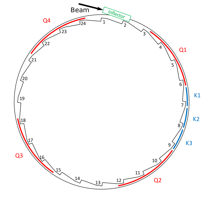
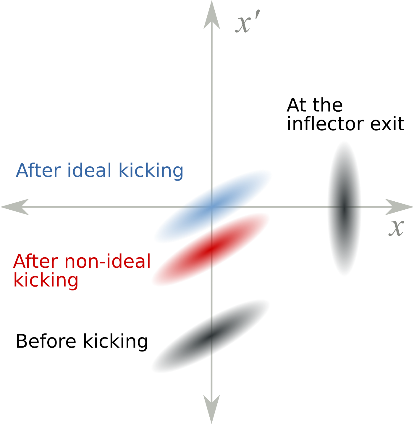
Figure 1 shows the top view of the storage ring. The beam is brought into the storage region through a superconducting septum magnet called the inflector [10]. After the beam exits the inflector magnet, it is kicked onto a stable orbit with a fast kicker [13]. The kicker provides a 200 Gauss vertical field with a 200 ns width. It lasts around 1 s with ringing. The limited space between the storage ring pole pieces necessitates a very narrow beam channel through the inflector magnet, making it impossible to match the incident beam phase space with that of the storage ring. The present strength of the kicker magnet is slightly less than needed to center the beam in the storage region. As one can infer from Figure 2, the mismatch of the phase space combined with the underkick leads to a significant radial beam oscillation after injection. It has a decoherence time of 200-300 s, which is not insignificant compared to the dilated muon lifetime of 64.4 s. This radial oscillation is called the “coherent betatron oscillation” (CBO) described below.
Assuming that is uniform and , the difference between this muon spin frequency and the cyclotron frequency is:
| (1) | |||||
| (2) | |||||
| (3) |
where the muon charge . This difference frequency provides a direct measurement of the magnetic anomaly. With the presence of the electric quadrupole field, and assuming that and , the spin equation is modified to [4]
| (4) |
For ( GeV/c) the electric field does not contribute to the rate at which the spin rotates relative to the momentum [14]. After approximately 30 turns around the ring, the spin angle relative to the momentum vector turns through .
When the stored muons decay, the highest energy positrons in the muon rest frame are correlated with the muon spin. As the muon spin precesses relative to the momentum vector, the number of high-energy decay positrons observed in the lab frame oscillates with the frequency . This feature is exploited by selecting the highest energy positrons in the calorimeters and measuring the muon spin precession rate in the horizontal plane.
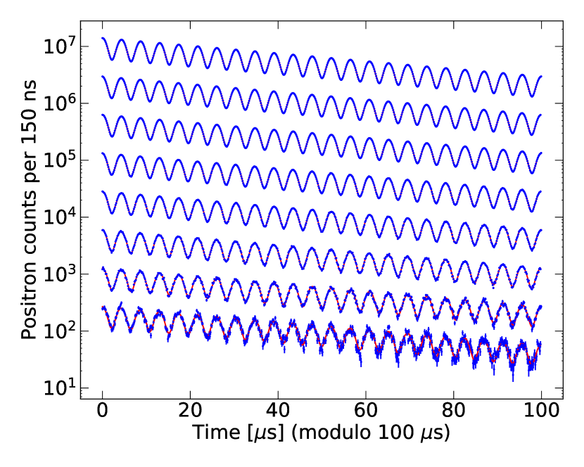
A sample time spectrum of high-energy electrons is shown in Figure 3. These data appear to show the muon lifetime modulated by the muon spin frequency , which can be represented by the "five-parameter function"
| (5) |
where is the number of particles per 149 ns time bin at , is the relativistic Lorentz factor, s is the lifetime of muon at rest, is the overall decay asymmetry, and is the phase. However, there is also information in these data on the coherent beam motion discussed below.
With a continuous pure electric quadrupole field around the ring to provide vertical focusing, the transverse motion of the beam follows the linear Hill’s equations:
| (6) | |||||
| (7) |
where MHz is the cyclotron frequency, and is the weak focusing field index, determined by the ring radius , the magnetic field , the particle velocity , and the electric quadrupole gradient :
| (8) |
The betatron frequencies in the horizontal and vertical directions are and , respectively.
The horizontal betatron oscillation frequency is slightly less than the cyclotron frequency. Therefore, a localized detector sees the beam oscillate inward and outward at MHz, namely the CBO frequency [5], defined as
An illustration of this motion is shown in Figure 4.
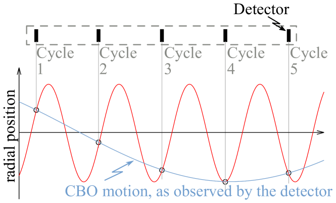
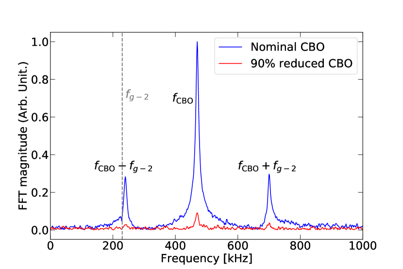
When the narrow time bunch muon beam enters the storage ring, each calorimeter sees the beam moving in and out with this CBO frequency. Because the detector acceptance depends on the radial position of the muon decay, this inward and outward motion of the bunched beam amplitude modulates the positron decay time spectrum. The principal issue is that its lower side band may overlap with if is close to , thereby pulling the phase. The effect can be significantly reduced, perhaps eliminated, if the CBO can be suppressed by an order of magnitude (see Figure 5). Note that this effect does not appear at the frequencies related to the vertical CBO. Therefore, our main focus will be on the horizontal motion.
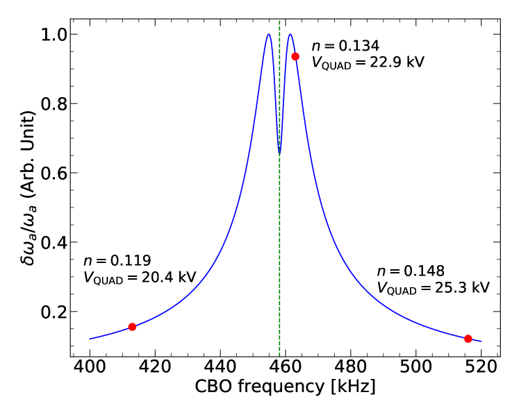
The CBO frequency depends on the -value of the ring, viz. the quadrupole voltage. As the CBO frequency approaches , the systematic pull on becomes significant, as discussed in section 5.1 of Ref. [15]. Figure 6 shows the relative systematic error from the CBO as a function of caused by the lower sideband overlapping with . An obvious strategy to minimize this issue would be to change the -value by increasing or decreasing the quadrupole high voltage in order to move away from the central region of Figure 6. However, raising the high voltage (higher ) increases the possibility of the quadrupoles sparking, and lowering the voltage (lower ) decreases the acceptance of the storage ring, resulting in fewer muons stored.
Coherent betatron oscillations were a well-known effect in the BNL data, which was discussed in the E821 papers [5, 16, 15]. In the analysis of Run 99 and later, Equation 5 is modulated with an additional term to modulate the acceptance, phase and asymmetry:
| (9) |
where is the lifetime of the CBO, is the modification of the acceptance, and is the CBO phase. This additional parametrization resulted in an acceptable dof, and a conservative systematic error of ppm (70 ppb) for this effect was assigned [5]. Because the total E989 error budget for the muon frequency is four times smaller, we need to reduce the CBO contribution on from 70 ppb to 30 ppb. Reducing the CBO amplitude will significantly reduce the risk associated with the choice of the functional form describing it.
The muon populations at the edge of the beam tend to hit the walls of the vacuum chamber before decaying, which causes a modified decay rate measurement at the detectors. This systematic error was reduced to 90 ppb level in the E821 experiment. It was achieved by scraping the beam halo against circular collimators with a 9 cm diameter through the asymmetrical powering method.
Immediately before the muon beam injection, the top and bottom plates on quadrupoles 1-4 were powered asymmetrically, as were the vertical side plates on quadrupoles 2 and 4. This asymmetric powering shifted the beam both vertically and horizontally onto the collimators. Five to fifteen microseconds later, the plate voltages were returned to a symmetric configuration with a 5 s time constant, centering the beam in the storage region [5, 18]. This procedure removed particles near the aperture and significantly reduced muon losses from the storage ring during the data collection period. The asymmetrical powering method has been utilized in the first two runs of E989 as well. An approximately s scraping time was used [19].
A major issue with this scraping method is that the beam can move through a resonance while going from the scraping high-voltage configuration to the final symmetric high voltage, causing unwanted muon losses.
In the next section, we introduce the RF reduction method for damping the CBO. Application of RF fields allows us to scrape the beam as well, while avoiding the unwanted muon loss. It is worth emphasizing that reducing the CBO effect ensures a better fitting result, in other words, a more sensitive measurement.
2 The RF reduction method: Analytical calculation of CBO reduction
The manipulation of charged particle beams in accelerators using radio frequency (RF) techniques has a long history, and many electron, proton and heavy ion storage rings have been built and operated. RF beam separators have also been utilized to improve the purity of secondary beams. Our method relies on damping the coherent betatron oscillations by applying a transverse RF electric field at the CBO frequency. Because of the limited muon lifetime, the application of the RF field should be finished within a few tens of microseconds.
Reduction of coherent betatron oscillations by RF fields was first proposed in 2003 as a potential upgrade to the BNL E821 storage ring experiment [17]. We present that discussion here, since this reference is not published.
To damp the CBO, a harmonically varying horizontal dipole electric field is applied to the beam out of phase with the CBO. The RF field is applied to the two vertical quadrupole plates, which begin at the longitudinal position and extend to .
| (10) |
where, is the initial CBO phase and is defined as
Setting the muon injection time to be , we obtain Equation 6, Hill’s equation for the horizontal component, with a harmonic driving term:
| (11) |
where
| (12) |
The definition of means that the muon passes through the damping electric field periodically with the revolution period , times, after which the RF perturbation is turned off. The exact solution of Equation 11 with given by Equation 12 is
| (13) |
| (14) |
where corresponds to . From Equation 14, one gets the solution at time , the time that the CBO damping finishes. At this time
| (15) |
Ideally, , or very close to zero after turns. After discussing the simulations of the RF method, we will compare this analytical formula with a simulation result in Section 3.3.
3 Simulations of the RF reduction method
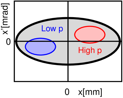
In this and subsequent sections, we follow the conventions of Figure 7 for both phase space ellipses and individual particles of low- and high- momentum in phase space.
3.1 Simulation strategy
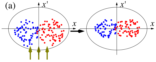
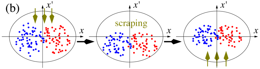
A dipole RF field with the resonant frequency can move the centroid of the beam along the vertical axis of the transverse phase space. It moves the high- () and low- () momentum populations together when they have the same CBO phase. Figure 8 shows the effect of the dipole RF field with on the phase space. Figure 8 (a) shows that by a correct choice of the RF phase, the beam can be shifted on the vertical axis to reduce the CBO amplitude. Figure 8 (b) shows that the dipole RF field can also be used in "scraping mode" before the measurement period by switching to the opposite RF phase.
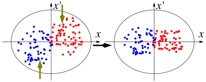
In contrast to the RF dipole mode, the RF quadrupole mode moves the high- and low-momentum populations in opposite directions. The beam width decreases as they reach the design orbit (see Figure 9).
3.2 Simulation conditions
The simulations of the RF reduction were done with a precision tracking simulation tool written in C++ [20]. All of the essential ring elements were implemented in the program, such as the electrostatic quadrupoles [18], the fast kicker magnets [13], the vacuum chamber, and the collimators. In these simulations, a 3 kV RF voltage was applied to one 3.2 m azimuthal quadrupole section.
As described above, the beam enters the E989 muon storage ring through the inflector section (shown in Figure 1), after which the simulations start with a beam distribution that was previously obtained by independent Monte Carlo simulations [21]. After the inflector, the fast kicker applies a vertical pulsed magnetic field to move the beam towards the design orbit. The beam motion in the phase space is depicted in Figure 2.
The electric quadrupole plates have a cross section of cm2 [18]. An RF voltage of 0.3 kV amplitude is applied to all eight quadrupole sections, covering 43% of the ring circumference. Particles are stored for up to 200 in the simulations.
3.3 Single Particle Simulations
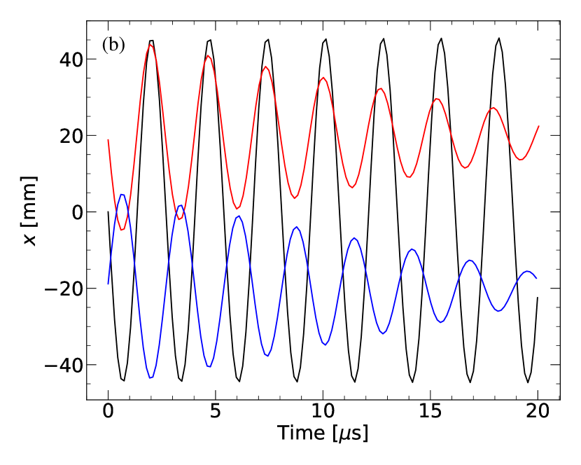
As a proof of principle, single particle simulations were conducted using three particles of different momenta: magic (), high- () and low- () momentum muons. In the absence of an RF field, each particle follows an elliptical trajectory in phase space, whose origin and radius are determined by its momentum and initial position.
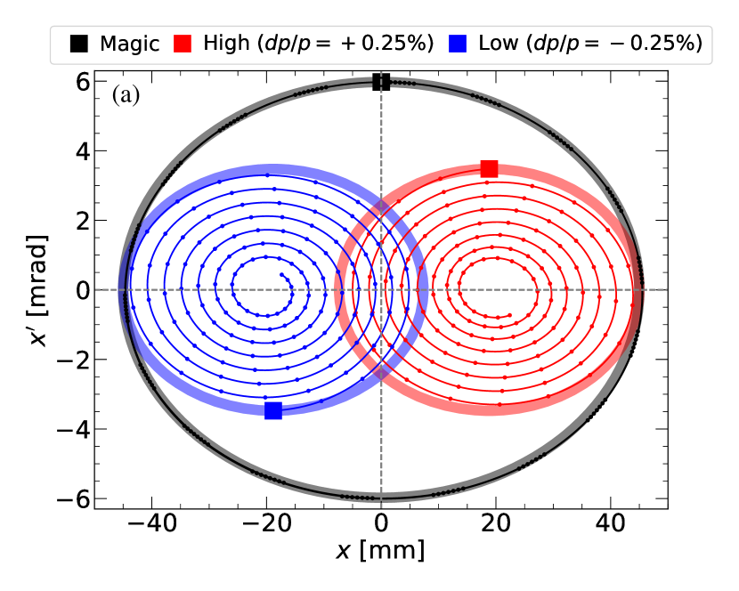
Figure 10 shows the phase space trajectory of each particle in the presence of the dipole RF field applied with the optimum phase. The method works best if the particles are in phase. If they are out of phase, then a dipole RF increases the amplitude of one, and shrinks the amplitude of the other. On the other hand, the RF quadrupole mode shrinks the high- and low-momentum particle orbits if they are out of phase (Figure 11). Note that the particle with magic momentum is not affected by the RF quadrupole field as it oscillates around the design orbit.
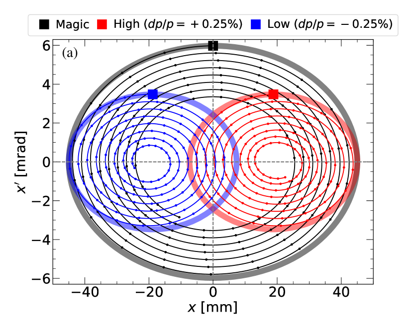

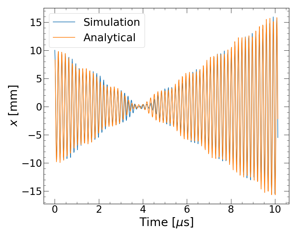
Figure12 shows the excellent agreement between the analytical calculation presented in Section 2 and the result from a single particle simulation. The parameters used in the calculation are: , m, , T, MHz, kHz and . Note that the RF field should be turned off at the minimum, after which the CBO starts growing because of resonance. In this example, it takes roughly oscillations to minimize the CBO amplitude. As seen here, amplitude damping with an opposing RF kick is the only effect for the single particle case. However, coupling between high- and low-momentum populations brings about a phase shift, a more dominant reduction effect. This will be presented in the next section.
3.4 Multiparticle Simulations
The multiparticle simulations were done with roughly 30,000 muons entering the storage ring. 95% of the particles hit the vacuum chamber or collimators and were lost after several turns around the ring.
The RF phase was initially optimized for the maximum CBO reduction without applying any scraping. After determining the optimum phase, the dipole RF field was applied from 2 to 7 s for the scraping and from 10 to 20 s for CBO reduction. Note that these two steps should have opposite phases.
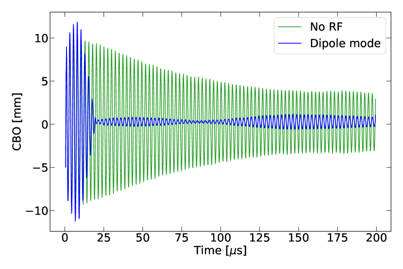
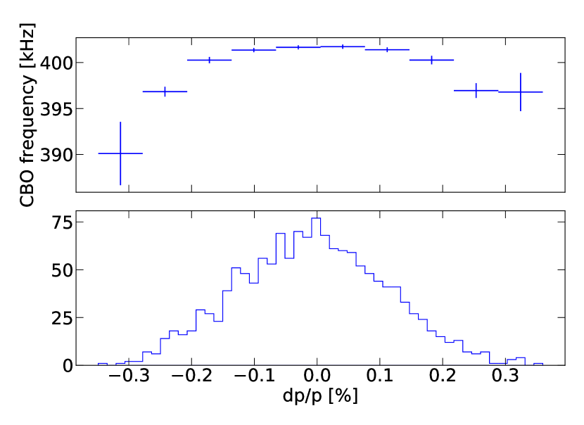
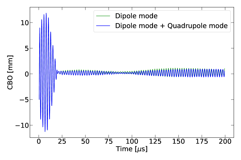
Figure 13 compares the CBO without RF, and with the applied RF field at the optimum phase. The CBO decoherence time is s in the absence of an RF field. The damping time depends on the momentum spread of the beam and the multipole components of the electric focusing field. Because of the electric 20-pole component, the CBO frequency of the different momentum muons varies, eventually leading to a decoherence (See Figure 14). However, the application of the RF field before 20 s improves the CBO damping by almost an order of magnitude. The beating after 20 s originates from the frequency spread of the beam shown in Figure 14.
The mechanism of the CBO reduction by a dipole RF field is shown in Figure 15. The initial conditions were obtained from Monte Carlo simulations [21]. As Figure 15 (b) shows, the RF dipole field reduces the CBO amplitude of both the high- and low-momentum populations. However, it is worth emphasizing that the reduction is not limited to a simple damping effect. In fact, the dominant effect is the phase shift between the two populations. The CBO phase of the high-momentum population advances with the RF kick, since it is closer to the origin of the phase space (see the tilt of the beam at Figure 2).
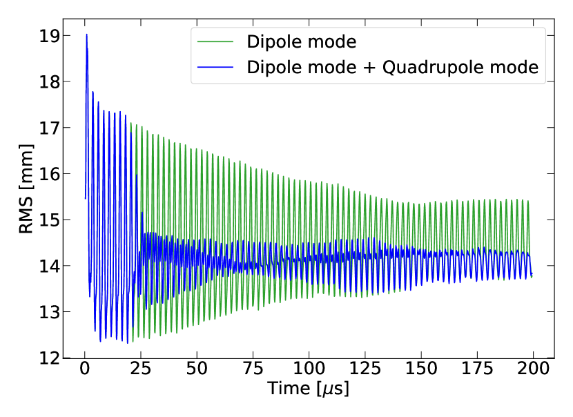
Applying the RF quadrupole field after the dipole mode does not have any effect on the beam centroid, as shown in Figure 16. However the RMS modulation of the beam is significantly reduced by the application of the RF field, as shown in Figure 17.
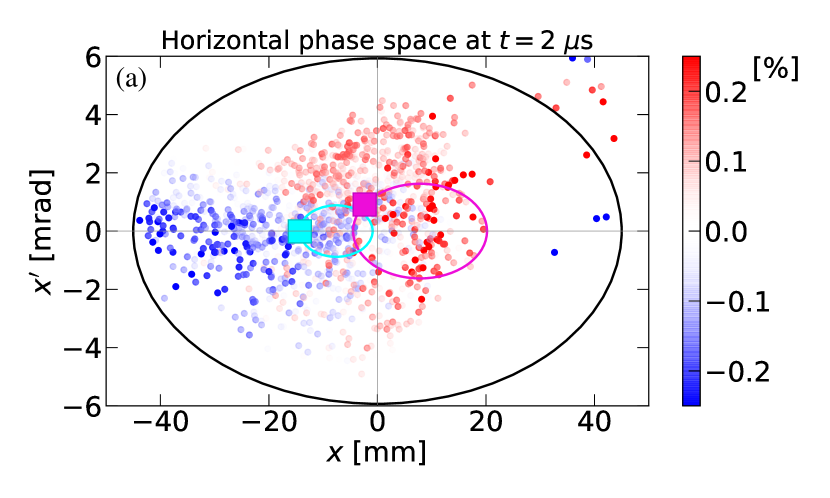
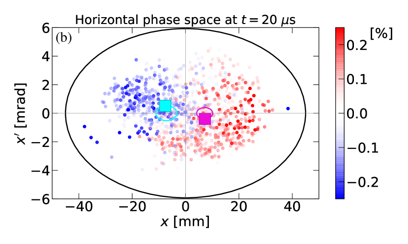
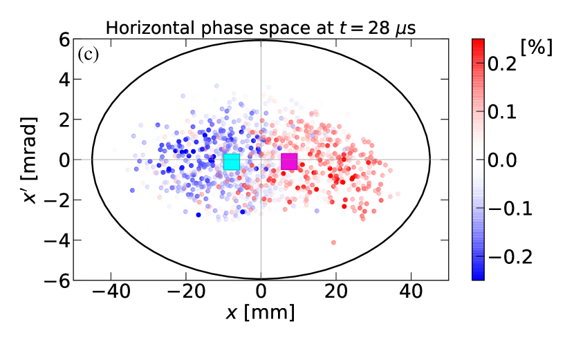
The total effect of the dipole and the quadrupole RF modes in the simulation are summarized in Figure 18, which shows three time slices of the phase space. The center of mass (CM) for the high-momentum population is represented by a purple square, and the phase space trajectory of the CM of the high-momentum particles is represented by a purple ellipse. The CM of the low-momentum particles is represented by a cyan box, and the phase space trajectory for this CM is shown by a cyan ellipse. Figure 18 (a) is before the application of the RF fields. The dipole RF mode is then applied to the beam for 20 s, resulting in opposite phases for the high- and low-momentum populations. Thus, the centers of the two trajectories have become symmetric around the design orbit.
This opposite phase for low- and high-momentum particles provides the ideal condition for the RF quadrupole mode to shrink the phase space of the muon beam. Figure 18 (c) shows how the RF quadrupole field shrinks the beam in phase space in the remaining 10 s.
4 Hardware
The muon beam is stored for around s with an average repetition frequency of 12 Hz. The quadrupole plates are pulsed in such a way that the at-voltage time coincides with the measurement time. The pulsed voltage is transferred to the quadrupoles through high voltage (HV) resistors with approximately s RC time constants. The E821-type scraping is also applied at this ramping period.
The quadrupole plates and cages are the same as used in E821 [18], with the exception of the first quadrupole (Q1), where the beam enters the storage ring through the quadrupole plate. Q1 has been redesigned and is significantly thinner than in E821. The E989 high voltage pulsing circuit is new and will be described in Ref. [22].
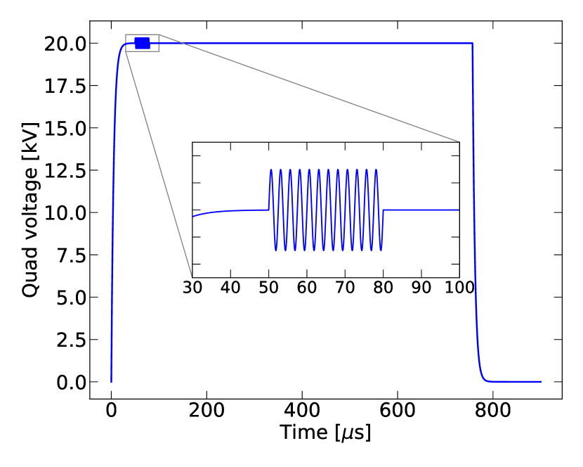
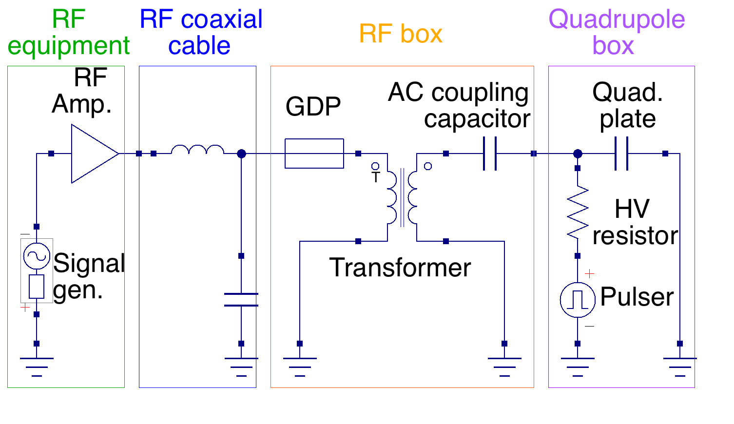
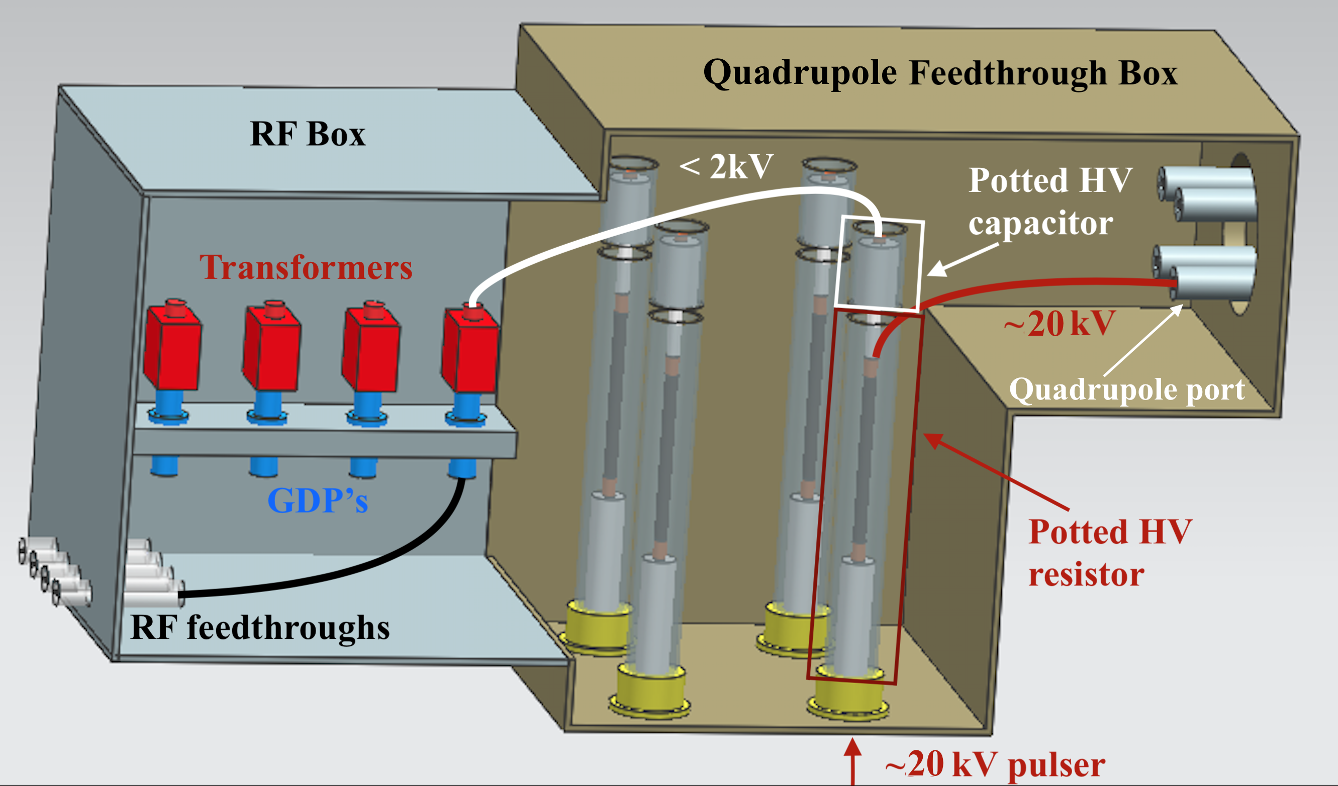
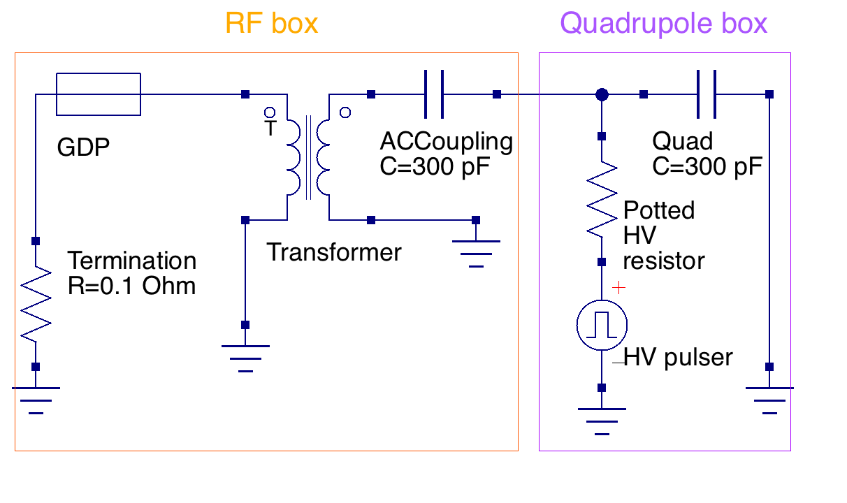
The RF voltage is superimposed on the HV pulses (Figure 19) to modulate the field at the quadrupole plates. Figure 20 shows the circuit diagram of the system. While the RF voltage is applied through the RF electronics on the left, the main field of the quadrupole is applied through a HV resistor. The RF electronics is protected by a gas discharge protector (GDP), which is connected to a transformer for impedance matching and a potted HV capacitor that couples the RF to the quadrupole plates. Figure 21 shows a 3D drawing of the installed system. There are four of each element in the box for each quadrupole plate.
The RF electronics is composed of trigger gate/delay generators, fan-in/fan-out modules, 7 signal generators, 13 HV pulsed amplifiers, and HV RF cables for every quadrupole plate. The main trigger for the quadrupole pulser is used for generating a gate of 40 s, which is copied for each signal generator and the amplifier. The signal generators are used in “arbitrary signal mode”, and controlled by means of a GUI. For CBO reduction and scraping with dipole fields, the arbitrary function is composed of two sinusoidal signals with integer number of oscillations, which are separated by a short gap to switch the phase. Each signal has a delay before the first sine wave, which is determined by the azimuthal location of the connected quadrupole. The RF amplifiers with dB gain deliver the signal through the HV RF cables to the RF box, which is depicted in Figure 21. The application of the RF system does not require any modification in the experimental conditions.
As mentioned earlier, the RF reduction method has an efficient scraping mode as well, which is preferable to the conventional method since the field index does not change during scraping in this method. Nevertheless, the RF electronics can be disconnected and the RF branch of the circuit can be shorted to the ground (shown with 0.1 Ohm resistor in Figure 22) for back compatibility with the original scraping scheme.
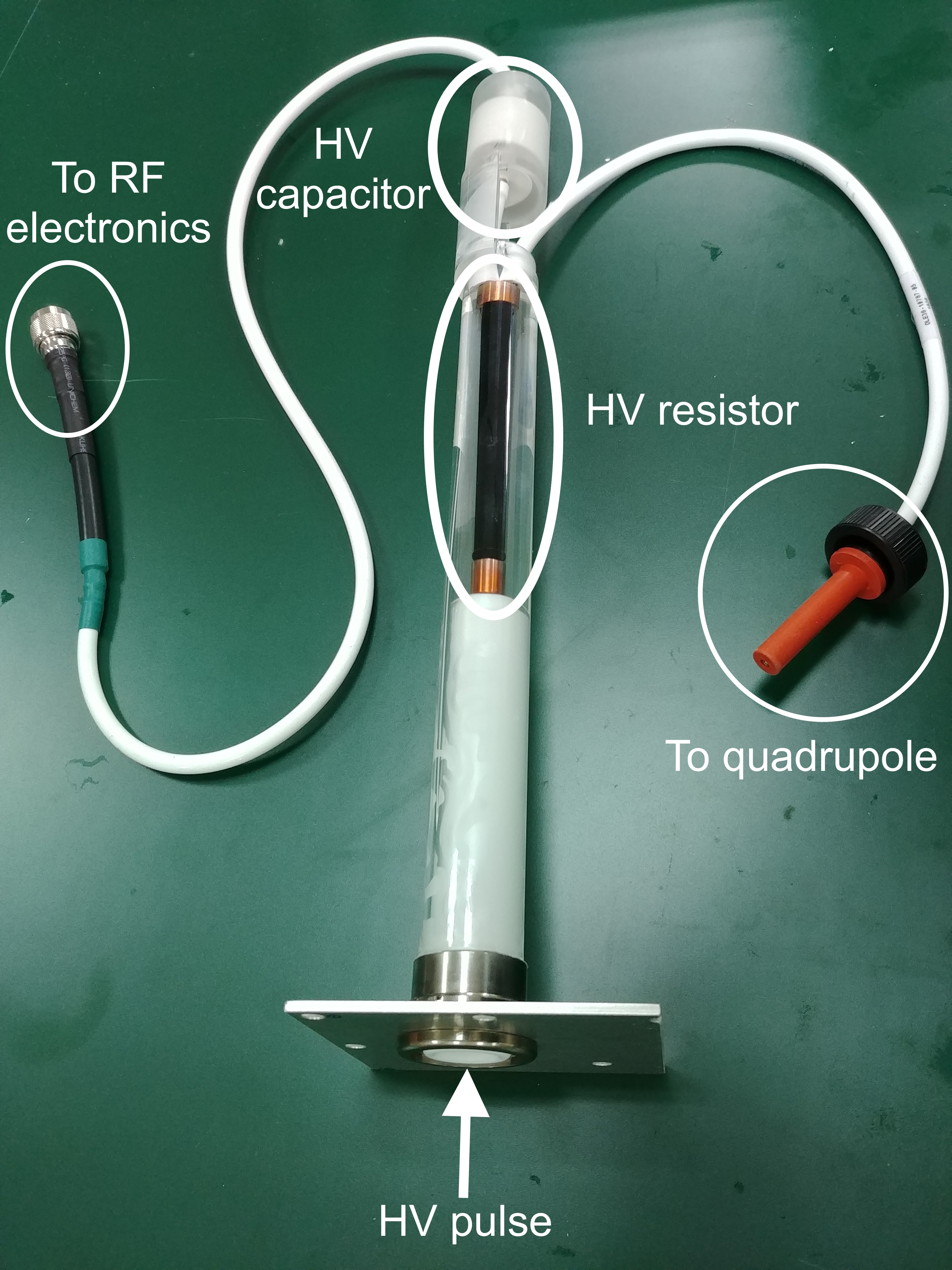
HV breakdowns are initiated by the emission of electrons from the cathode to anode at high voltages. The exchange of charged particles between the cathode and anode can be enhanced through several mechanisms [23, 24, 25]. One way of avoiding electron HV breakdowns is to eliminate the contact between the air and conductors. The HV resistors and capacitors are potted in respective containers with silicone elastomer (SE) for this purpose (Figure 23).
5 Test results
The hardware was tested by installing the RF system into all of the quadrupole sections in the E989 experiment. A 450 V amplitude RF voltage with an azimuthally dependent phase was applied to all of the quadrupole sections. The voltage was split between the long and the short quadrupoles by an HV divider. The motion of the beam centroid was extracted from the tracker detector [26] data.
Figure 24 shows the CBO amplitude damping rate that is obtained during the phase scan. Negative and positive values indicate CBO reduction and growth, respectively. The maximum reduction happens at .
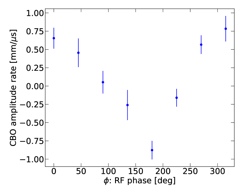
Figure 25 shows the CBO measurement at the RF phase . Initially, the CBO amplitude is mm. The RF field starts at s, reducing the CBO amplitude to mm at s. Then, it grows similar to Figure 12 with the RF field. It is worth noting that the CBO phase flips by after the crossover. This feature was exploited for scraping the beam.
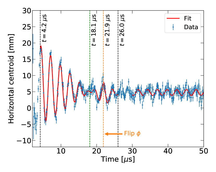
We continued the application of the RF field at the same phase for scraping the beam. Then, the RF field was flipped by at s. Finally, it was turned off at s. At that time, the CBO amplitude reduced back to 1 mm after scraping. The whole CBO reduction and the scraping process took around s.
The tests reveal that RF scraping produces results comparable to those of conventional scraping. Measurement of the betatron frequencies shows that the RF scraping and the CBO reduction do not affect the beam dynamics after the RF time is over.
6 Conclusions
This work represents the first successful development of the hardware necessary to apply RF cooling to a tertiary particle beam. Unlike primary beams in storage rings, where RF manipulation can occur over millisecond time scales, the muon time dilated lifetime of s severely limits the time available for beam manipulation, if there is to be a significant measurement time following the beam cooling period.
The RF reduction method described here has been shown to significantly reduce the CBO while achieving loss of muons comparable to that which occurs during conventional scraping. This improvement is essential to determine the muon spin rotation frequency, and thereby the muon magnetic anomaly with an unprecedented sensitivity.
7 Acknowledgements
This work was supported by IBS-R017-D1 of the Republic of Korea, and also in part by Fermi Research Alliance, LLC under Contract No. DE-AC02-07CH11359 with the U.S. Department of Energy, Office of Science, Office of High Energy Physics. The U.S. university groups were supported by U.S. DOE Office of High Energy Physics research grants. We would also like to thank the many collaborators who have helped us with this project. We also would like to thank Sidney Orlov for improving the readability of the paper.
References
- [1] J. P. Miller, E. de Rafael, and B. L. Roberts, Muon g-2: Review of Theory and Experiment, Rept. Prog. Phys. 70 795, https://doi.org/10.1088/0034-4885/70/5/R03 (2007).
- [2] J. Bailey et al., Precision measurement of the anomalous magnetic moment of the muon, Phys. Lett. B28, 287 (1968).
- [3] J. Bailey et al., Precise measurement of the anomalous magnetic moment of the muon, Il Nuovo Cimento A 9, 369 (1972).
- [4] J. Bailey et al., Final report on the CERN muon storage ring including the anomalous magnetic moment and the electric dipole moment of the muon, and a direct test of relativistic time dilation, Nucl. Phys. B 150, 1 (1979).
- [5] G.W. Bennett et al., Final report of the E821 muon anomalous magnetic moment measurement at BNL, Phys. Rev. D 73, 072003 (2006).
- [6] M. Davier et al., Reevaluation of the hadronic vacuum polarization contributions to the Standard Model predictions of the muon and using newest hadronic cross-section data, Eur. Phys. J. C 77, 827 (2017).
- [7] A. Keshavarzi et al., Muon and : A new data-based analysis, Phys. Rev. D 97, 114025 (2018).
- [8] J. Grange et al., Muon Collaboration, Muon technical design report, arXiv:1501.06858 (2015).
- [9] G. T. Danby et al., The Brookhaven muon storage ring magnet, Nucl. Inst. and Meth. A 457 151-174, https://doi.org/10.1016/S0168-9002(00)00704-X (2001).
- [10] A. Yamamoto et al., The superconducting inflector for the BNL g-2 experiment, Nucl. Inst. and Meth. A 491 23-40, https://doi.org/10.1016/S0168-9002(02)01232-9 (2002).
- [11] N. S. Froemming et al., Commissioning the superconducting magnetic inflector system for the muon g-2 experiment, IPAC’18 Proceedings, https://doi.org/10.18429/JACoW-IPAC2018-WEPAF014 (2018).
- [12] E. Efstathiadis et al., A fast non-ferric kicker for the muon (g-2) experiment, Nucl. Inst. and Meth. A 496 8-25 (2003).
- [13] A.P. Schreckenberger et al., New Fast Kicker Results from the Muon g-2 E-989 Experiment at Fermilab, Proc. 9th International Particle Accelerator Conference, doi "10.18429/JACoW-IPAC2018-THPML093", http://lss.fnal.gov/archive/2018/conf/fermilab-conf-18-167-e.pdf.
- [14] J. P. Miller and B. Lee Roberts, The Muon Spin Equations, the Magic , What’s small and what’s not, arXiv:1805.01944v2 (2018).
- [15] G.W. Bennett et al., Statistical equations and methods applied to the precision muon experiment at BNL, Nucl. Inst. and Meth.A 579, 1096 (2007).
- [16] G.W. Bennett et al., Measurement of the Negative Muon Anomalous Magnetic Moment to 0.7 ppm, Phys. Rev. Lett. 92, 161802 (2004).
- [17] Y.F. Orlov and Y.K Semertzidis, To get rid of CBO (and to get scraping without resonance crossings), Muon g-2 Note 431 (2003), unpublished.
- [18] Y.K. Semertzidis et al., The Brookhaven muon () storage ring high voltage quadrupoles, Nucl. Inst. and Meth. A 503, 458 (2003).
- [19] J.D. Crnkovic et al., Commissioning the Muon g-2 Experiment Electrostatic Quadrupole System, IPAC2018 Proceedings, https:// doi.org/10.18429/JACoW-IPAC2018-WEPAF015 (2018).
- [20] E.M. Metodiev et al., Analytical benchmarks for precision particle tracking in electric and magnetic rings, Nucl. Inst. and Meth. A 797 311-318 (2015).
- [21] D. Rubin, private communications (2017).
- [22] J.D. Crnkovic et al., Commissioning the Electrostatic Quadrupole System for the Muon g-2 Experiment, in preparation.
- [23] R. Latham, High voltage vacuum insulation, Academic Press (1995).
- [24] G. Farrall, IEEE Trans. Electr. Ins., EI-20, 815 (1985).
- [25] R. Morrow and D. Weisser, Vacuum breakdown mechanisms, and X-ray pulses in accelerators, Nucl. Instr. and Meth. A, 382, 66-72 (1996).
- [26] J. Mott et al., The readout system for the Fermilab Muon g-2 straw tracking detectors, ICHEP2016 Proceedings, http://doi.org/10.22323/1.282.1163 (2018).