Nano-scale magnetic skyrmions and target states in confined geometries
Abstract
Research on magnetic systems with broken inversion symmetry has been stimulated by the experimental proof of particle-like configurations known as skyrmions, whose non-trivial topological properties make them ideal candidates for spintronic technology. In this class of materials, Dzyaloshinskii-Moriya interactions (DMI) are present, which favor the stabilization of chiral configurations. Recent advances in material engineering have shown that in confined geometries it is possible to stabilize skyrmionic configurations at zero field. Moreover, it has been shown that in systems based on Pd/Fe bilayers on top of Ir(111) surfaces skyrmions can be as small as a few nanometres in diameter. In this work we present scanning tunneling microscopy measurements of small Pd/Fe and Pd2/Fe islands on Ir(111) that exhibit a variety of different spin textures, which can be reproduced using discrete spin simulations. These configurations include skyrmions and skyrmion-like states with extra spin rotations such as the target state, which have been of interest due to their promising dynamic properties. Furthermore, using simulations we analyze the stability of these skyrmionic textures as a function of island size, applied field and boundary conditions of the system. An understanding of the parameters and conditions affecting the stability of these magnetic structures in confined geometries is crucial for the development of energetically efficient and optimally sized skyrmion-based devices.
I Introduction
Recent advances on the study and fabrication of ferromagnetic systems with broken inversion symmetry have been highly motivated by the experimental observation of topologically non-trivial and spatially localized particle-like magnetic configurations known as skyrmions. The theoretical predictions of skyrmions and skyrmion lattices in ferromagnetic materials with Dzyaloshinskii-Moriya interactions (DMI)Bogdanov et al. (1989); Bogdanov and Yablonskii (1989); Rößler et al. (2006) were first confirmed by Mühlbauer et al. Mühlbauer et al. (2009) and later in numerous experimental studies where non-collinear structures were observed by imaging the magnetic texture of a sample. In particular, scanning tunneling microscopy with a spin-polarized tip Heinze et al. (2011); Romming et al. (2013, 2015); Wiesendanger (2016) (SP-STM) has been effective for sampling, with atomic-scale resolution, the presence and structure of individual skyrmions in interfacial systems. Studies based on the SP-STM technique applied to Pd/Fe films on an Ir(111) surface, where skyrmions need to be stabilized using an external magnetic field, have shown that individual skyrmions can be created and annihilated Romming et al. (2013) and how their size and shape depends on the field strength. Romming et al. (2015) Besides skyrmions, other non-collinear structures have been experimentally observed as equilibrium states. For example, spin spirals arise as the ground state in Pd/Fe bilayers at zero field Romming et al. (2013) and experiments show phases where skyrmions coexist with spin spiral configurations. Furthermore, the theory predicts different symmetrical configurations similar to skyrmions with additional rotations Bogdanov and Hubert (1994a, 1999), which are known in the literature as -skyrmions, with according to the number of rotations.
A -skyrmion corresponds to a particle-like configuration with two radially symmetric spin windings and is also known in the literature as the target state.
Target states have been predicted by theory Bogdanov and Hubert (1994a, 1999) and observed in micromagnetic Rohart and Thiaville (2013); Leonov et al. (2014); Beg et al. (2015); Liu et al. (2015); Carey et al. (2016); Pepper et al. (2018); Kolesnikov et al. (2018) and atomistic Hagemeister et al. (2018) simulations. It has been claimed that the dynamics of target states caused by spin waves Shen et al. (2018); Li et al. (2018), field gradients Komineas and Papanicolaou (2015a) or spin-polarized currents Komineas and Papanicolaou (2015b); Liu et al. (2015); Zhang et al. (2016); Kolesnikov et al. (2018) present some differences with that of skyrmions, such as keeping a steady motion after switching off the current. Other effects make evident their advantage over skyrmions for their manipulation in two dimensional systems, such as racetrack geometries. These include not being affected by the skyrmion Hall effect, Nagaosa and Tokura (2013) because their net topological charge is zero, reaching larger velocities under currents applied perpendicular to the hosting material, Zhang et al. (2016); Kolesnikov et al. (2018) and not exhibiting distortion under certain conditions during their motion. Zhang et al. (2016); Komineas and Papanicolaou (2015a) Although recent experiments have reported the observation of target states in the ferrimagnetic Finazzi et al. (2013) , the ferromagnet next to a topological insulator, Zhang et al. (2018) and the chiral magnet Zheng et al. (2017) FeGe, thus far no evidence has been provided for thin ferromagnetic layers next to a heavy metal, where interfacial DMI is present.
Experimental studies of chiral materials have recently focused on the analysis of skyrmionic textures in confined geometries. Zheng et al. (2017); Jin et al. (2017); Zhang et al. (2016); Ho et al. (2019) Theoretical investigations have shown that in confined geometries skyrmions and target states can be stabilized at zero field, Beg et al. (2015); Pepper et al. (2018) which is of significant importance for the potential design of skyrmion-based spintronic devices. Wiesendanger (2016); Fert et al. (2017)
A notable feature of skyrmions in interfacial Pd/Fe samples is their small size of only a few nanometers in radius, which can be an important step forward towards the miniaturization of magnetic technology. This is in contrast with skyrmions in bulk materials such as FeGe, where the helical length is about . The same holds for target states, which were observed in diameter cylinders. Zheng et al. (2017) Although the stabilization of skyrmionic textures in extended Pd/Fe bilayer samples requires the application of a magnetic field, confined geometries offer an alternative for observing these structures at zero or weak field strengths. It is important to notice that at this low field regime, spiral structures are energetically favored over skyrmions since the DMI and exchange energies dominate over the Zeeman energy. Hence, it is important to gain an understanding of ranges of parameters where spin spirals, skyrmions and target states are stable for their potential observation in small confined interfacial systems.
In this work we show through SP-STM measurements and numerical simulations, that a variety of chiral configurations can be stabilized in small Pd/Fe/Ir(111) islands of about in diameter. We reproduce the experimental images using simulations based on a discrete spin model. We validate the simulations of the islands by comparing the tilting of spins at the boundary with the experimental findings. Simulations show that a variety of the experimentally observed chiral configurations are accessible through a magnetic field sweep and we characterize them through their topological number. Furthermore, we show that the confinement within the islands allows the stabilization of skyrmion-like configurations, such as a target state or a -skyrmion, from zero field up to a wide range of magnetic fields below T.
In addition to the analysis of Pd monolayer islands on Fe/Ir(111), we show STM images of Pd double layer islands on Fe/Ir(111) with the presence of a configuration resembling a target state. In this system the environment of the islands in applied field is ferromagnetic owing to the surrounding field-polarized Pd/Fe layer. To understand the stability of skyrmions and target states under different boundary conditions we perform a systematic study of these configurations in perfectly shaped hexagonal islands under different conditions. In this context, we compute the skyrmion and target state size and energy as a function of island size, applied field, and boundary condition. Moreover, we vary these parameters to calculate the ground states of the system, which reveals conditions for the stability of different -skyrmion states.
As an additional proof for the stability of skyrmions and target states, we calculate the energy barrier separating a skyrmion from the uniform ordering and the barrier between a target state and a skyrmion. We compute the barriers using the Geodesic Nudged Elastic Band Method (GNEBM) Bessarab et al. (2015) which has been previously used to compute transitions with the least energy cost between equilibrium configurations in finite chiral systems. Cortés-Ortuño et al. (2017); Stosic et al. (2017); Bessarab et al. (2018); Hagemeister et al. (2018) Our results show that the stability of target states benefits from ferromagnetic boundaries, in agreement with our experimental findings.
We start this paper by introducing in Sec. II results obtained with SP-STM measurements on the Pd monolayer islands on Fe/Ir(111) together with the theoretical basis for the simulation of these systems. Consequently, in Sec. II.2 we show discrete spin simulations of the experimentally fabricated quasi-hexagonal hcp Pd islands on fcc Fe. Using different initial states we reproduce the field sweep experiment in these islands in Sec. II.3. In Sec. III we discuss additional experiments performed on Pd islands on an extended Pd/Fe film on Ir(111) and simulations of these samples with ferromagnetic boundary conditions. To obtain an understanding of the experimental observation of magnetic orderings resembling a target state in the Pd2/Fe islands, in Sec. IV we model perfectly hexagonal islands and study the energy and size of skyrmions and target states as a function of hexagon size, applied field and boundary conditions. In addition, we characterize the lowest energy states with a full phase diagram of the hexagon system in Sec. IV.2. Finally, in Sec. IV.3 we study the stability of skyrmions and target states by means of energy barrier and energy path calculations with the GNEBM.
II Magnetic states in Pd/Fe/Ir(111) islands
II.1 Experimentally observed magnetic states
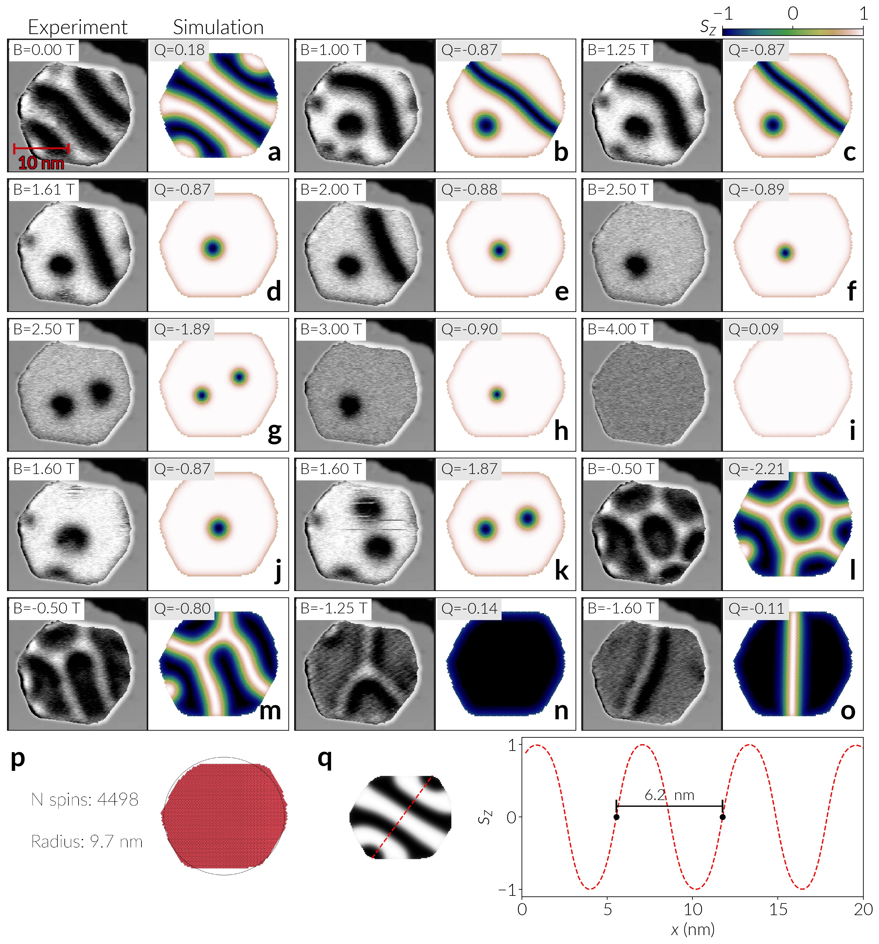
Spin-polarized scanning tunneling microscopy (SP-STM) is a valuable tool to study nano-scale magnetism in model-type systems. Wiesendanger (2009) Figure 1 shows spin-resolved maps of the differential conductance (left columns) of a monolayer thick hcp-stacked Pd island on an extended fcc-Fe monolayer on Ir(111) at different applied out-of-plane magnetic fields as indicated (cf. Supplemental Material, Sec. S1, for sample preparation sup ). The presented data is obtained at a bias voltage of and the observed signal changes within the roughly hexagonal island are due to a combination of tunnel magnetoresistance and non-collinear magnetoresistance Wiesendanger (2009); Hanneken et al. (2015) (cf. Supplemental Material Sec. S2 for more details sup ). In this case the tip is predominantly sensitive to the out-of-plane magnetization component of the sample. The Pd-covered Fe (Pd/Fe bilayer) behaves as one magnetic entity: the magnetic state of the Fe is changed by the hybridization with the Pd layer and the Pd becomes spin-polarized. The Pd/Fe bilayer exhibits a spin spiral ground state at zero magnetic field, as evident from the stripes observed in the differential conductance map in (a). Romming et al. (2013) Furthermore, a Pd/Fe island is surrounded by the Fe monolayer, where a highly non-collinear nano-skyrmion lattice Heinze et al. (2011) is present. This nano-skyrmion lattice does not change its state upon the application of an external magnetic field and has a magnetic period of about 1 nm. As this is small compared to the characteristic spin spiral wavelength of nm in Pd/Fe/Ir(111), we have neglected a possible weak coupling between these layers in the theoretical model, that we describe later, treating the island edges as free boundaries.
The investigated hexagonal island has a circumradius of about (see (p)) and the zero magnetic field spin spiral period is about 6 nm. This spiral adjusts to the shape of the island by bending the stripes to be more perpendicular to the island edges, see (a). When a magnetic field is applied, the sample magnetization changes and at intermediate magnetic fields we observe a skyrmion next to a wall, whereas at larger magnetic fields only skyrmions are observed, see Fig. 1(b)-(h). Because of the injection of higher energy electrons at the used bias voltage the tunnel current can induce changes in the sample magnetization, compare (f) and (g), which are measured at the same applied magnetic field but one skyrmion has appeared between the two measurements. At the sample reaches a uniform magnetization, see Fig. 1(i). When the applied magnetic field is reduced again similar magnetic states reappear, i.e. at one or two skyrmions are found in the island, see (j) and (k).
However, when the applied magnetic field is then increased in the opposite direction the magnetic configuration of the island is dominated by a network of domain walls and their junctions, see Fig. 1(l)-(n). These states are unusual magnetic configurations and we think they arise when a magnetic field is applied to a zero-field state that is not the virgin state but a metastable remanent state. We would like to point out the central region of (l), which resembles a magnetic skyrmion with the center (dark) parallel to the applied magnetic field and the surrounding (bright ring) magnetized opposite to the applied magnetic field; this means that this skyrmion has an equivalent spin texture as the one observed in (f), but it exists here in the opposite magnetic field. When the absolute value of the applied magnetic field is increased, more and more junctions of walls disappear until when only one domain wall remains; this is a state similar to the one found when the magnetic field is applied to the virgin state, see Fig. 1(d), which shows a similar domain wall next to a skyrmion.
To obtain a better understanding of the magnetic field dependent stability and topological properties of the observed magnetic states in this particular Pd/Fe island, we performed discrete spin simulations of each magnetic state at the given applied magnetic field using the Fidimag Bisotti et al. (2018) code. We translate the quasi hexagonal experimental Pd/Fe/Ir(111) island into a spin lattice, as illustrated in Fig. 1(p). We treat the Pd/Fe bilayer as a single entity and consequently simulate a monolayer of spins in a two-dimensional triangular lattice. The islands are simulated with open boundaries because of the Fe/Ir environment of the island explained earlier in this Section. By setting the island in the -plane we use the following Heisenberg-like Hamiltonian,
| (1) |
In Eq. 1 is the magnetic moment of the spin at the lattice site , is the corresponding spin orientation with , is the number of spins, which depends on the lattice constant and the size of the island, is an effective anisotropy taking into account the uniaxial anisotropy and the approximation of the dipolar interactions, is the DMI constant that describes the interfacial DMI for this material and the last term is the Zeeman interaction for the field applied perpendicular to the sample plane.
For the hcp stacking of Pd on fcc-Fe, as in this island, the continuum magnetic parameters , , and (exchange stiffness, DMI, and effective uniaxial anisotropy) have been obtained from previous experiments Romming et al. (2015), hence we convert these values into the equivalent discrete magnitudes (see Sec. S5 in the Supplemental Material for details sup ). These parameters define a characteristic helical length Leonov et al. (2016) at zero field and zero anisotropy of , where is the in-plane atomic spacing of PdFe. As in the previous work Romming et al. (2015) we approximate dipolar interactions into the anisotropy since, in the ultrathin film limit, their energy contribution become significantly small Leonov et al. (2016); Lobanov et al. (2016); Wang et al. (2018) and it is possible to approximate them as a uniaxial anisotropy, von Malottki et al. (2017) in particular for axisymmetric solutions (which can be proved analytically Bogdanov and Hubert (1994a)). Note that if the stray field is taken explicitly as in Ref. Kiselev et al., 2011 the anisotropy constant is likely to have a smaller magnitude.
The results of relaxing a particular experimentally found magnetic state at the applied magnetic field are shown in the right columns of Fig. 1. In general, the simulations are highly accurate in reproducing the magnetic configurations from the experiments at the corresponding applied fields. In particular, from Fig. 1(q) the period of the spiral at zero field of (a) is estimated as 6.2 nm, in agreement with the characteristic helical length period. Discrepancies arise for the magnetic states shown in Fig. 1(d), (e) and (n). In these cases, different factors that are not considered in the theoretical model, such as the presence of defects, might be contributing to the stabilization of the experimentally observed domain walls and branches.
The topological charge of each of the simulated spin textures in the Pd/Fe island can be calculated according to the method presented in Refs. Berg and Lüscher, 1981; Yin et al., 2016; Cortés-Ortuño et al., 2017. This quantity is a mathematical measure of the number of times that the spin orientations, on a two dimensional plane, wrap a unit sphere. It is useful, for example, for quantifying the number of skyrmions in a system as the spin configuration of each skyrmion in an infinite sample contributes with . For magnetic states in a confined geometry, such as this Pd/Fe island, the topological charge is usually not an integer due to the edge tilt of the spin texture at the boundary of the structure.
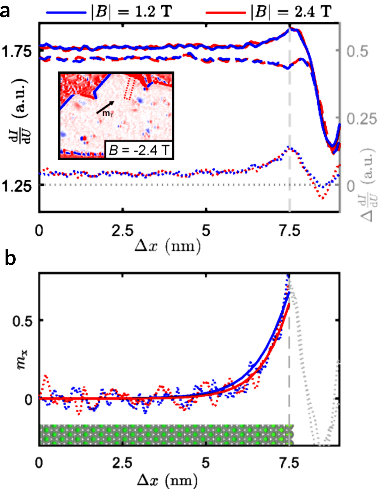
Figure 2(a) shows the line profiles of the differential conductance near the edge of a larger Pd/Fe island at four different applied magnetic fields, using a bias voltage of mV. The tip magnetization axis was derived from the appearance of the skyrmions in this measurement and was found to be dominantly in the surface plane (see inset to Fig. 2(a) and Sec. S3 in the Supplemental Material sup ). The in-plane component of the sample magnetization can be calculated from the data presented in (a) and is plotted as dotted lines for the two different absolute applied magnetic fields in (b). The solid lines in Fig. 2(b) represent the -component of the respective simulated data. Although the simulations do not include a possible change of the magnetic material close to the edge due to changes of the electronic structure, the agreement with the experimental profiles is remarkable. As evident from the experimental profiles and the calculated magnetization component , the DMI indeed leads to a considerable tilting of spins at open boundaries of up to with respect to the surface normal. The negligible difference between the profiles at and shows the comparably small influence of the external magnetic field on the edge tilt.
Comparison between Fig. 1(c) and (d) demonstrates that a domain wall does not have a topological charge. Because the absolute value of the topological charge of a skyrmion is 1, and depending on the applied magnetic field, we can conclude that for the island shown here the edge tilt contributes to the total topological charge in a small range of , which confirms the weak influence of the field. Analyzing the unusual magnetic configurations found in the experiments, Fig. 1(l), (m), we find that they have a topological charge with the same sign as the external magnetic field, in contrast to the typical skyrmion states (e.g. (f)) where the topological charge and magnetic field have opposite signs.
II.2 Simulations of magnetic states in the island
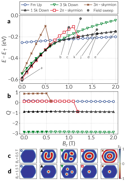
To compare the experimentally observed magnetic states with other possible equilibrium states we analyze the energy and the topological charge of different simulated magnetic structures. For these simulations we define five different initial states and relax them using the Landau-Lifshitz-Gilbert equation at different magnetic fields, see Fig. 3: a uniform ordering () with edge tilt, a single skyrmion (), three skyrmions ( ), a target state (), or -skyrmion, and a -skyrmion (), which is a target state with an extra rotation of the spins. At the bottom of Fig. 3 we show relaxed states of the five configurations at applied fields of and . They do not look the same for both fields because lower energy states can be found during relaxation or some of the configurations are unstable in specific ranges of the applied magnetic field. Note that at weak magnetic fields the skyrmions tend to occupy a larger area and are deformed because of the inter-skyrmion force and the boundary repulsion.
The energies of the magnetic states (Fig. 3(a)) are calculated with respect to the energy of a completely uniform configuration where spins point in the direction and that we denote by . Therefore, the energy curve labelled as “Fm Up” resembles the energy gain of the edge tilt. The ground state of the system for magnetic fields close to zero is likely to be a spiral with multiple rotations, since after analyzing the energy of different variations of spirals obtained from the simulations we found that they usually have lower energy than the five configurations shown. We do not show the spirals here since they are not easily classifiable. With increasing fields the Zeeman interaction becomes predominant and these spirals are not energetically favored anymore.
We can distinguish some of the configurations by their topological charge, which we show in Fig. 3(b). These values are not integers due to the tilting of the spins at the boundaries. For domains magnetized out-of-plane and enclosed by a domain wall, such as a skyrmion, there is associated a topological charge of one. We find that the FM state, the single skyrmion, and three skyrmions do not change their topological number in the entire magnetic field range, whereas the -skyrmion and the -skyrmion have a smaller stability range and decay into other magnetic states: the -skyrmion state changes at to a -skyrmion state, and the -skyrmion state changes at to a single skyrmion state.
At weak fields, below 0.7 T, a single skyrmion becomes a worm-like domain, as shown in the second image from the left in Fig. 3(c). This transformation is known in the literature as strip-out or elliptic instability. Bogdanov and Hubert (1994b); Leonov et al. (2016) We mark the worm domains by filled data symbols in Fig. 3(a) and (b) (i.e. a filled black triangle, instead of a hollow black triangle). A transition of such a worm-like domain into a circular domain exists for and (Fig. S5 in the Supplemental Material sup shows both configurations). This is confirmed by analyzing the energy of the magnetic interactions involved, which are shown in Sec. S6 of the Supplemental Material sup . The worm domain has lower energy than a circular domain at weak fields because of the DMI energy, which dominates over the Zeeman energy, and favors larger areas of non-collinear spin ordering. Similar horseshoe-like states have been observed previously in disk samples with DMI Beg et al. (2015); Ho et al. (2019) for sufficiently large system sizes. As the magnetic field increases, both the DMI and Zeeman energies of a worm domain increase up to a point where the structure is not energetically stable anymore and a transition into the circular domain occurs, which sets the skyrmion strip-out field. Here, the DMI energy abruptly increases but is followed by a steep decrease of the energies of the three other interactions. In simulations, the worm domain is only found by relaxing the system with a very strict (i.e. small) numerical tolerance of the algorithm (see simulation details in Supplemental Material, Sec. S7 sup ). For weaker (i.e. numerically greater) tolerances we observe that the skyrmion relaxes to a circular bubble-like domain.
We see in Fig. 3(a) that close to a field of a single skyrmion (which is observed above ) has lower energy than three skyrmions in the sample, partially due to the Zeeman energy which is smaller for a larger ferromagnetic environment in the direction of the applied field. Furthermore, above a field of a single skyrmion and three skyrmions start having larger energy than the uniform configuration. In the case of three skyrmions, it is still possible to observe worm domains, however their presence depends on the available space in the island. This can be seen from Fig. 3(c), where only one of the skyrmions is deformed into an elongated domain at weak fields. Three skyrmion states with a worm domain are also indicated with filled data points in Fig. 3(a) and (b). The presence of a small elongated domain also affects the energy of the system, where the transition occurs at fields from 0.5 T up to 0.6 T, but not as abruptly as in the case of a single skyrmion because of the smaller skyrmion size. As indicated in Fig. S4 of the Supplemental Material, sup although the DMI energy behaves similarly as in the single skyrmion case, the Zeeman energy does not change significantly when the small worm domain turns into a circular skyrmion, hence other effects such as the skyrmion-skyrmion interaction, the island confinement and the repulsion from the boundary, become more important in hindering the formation of spiral domains.
Two other physically interesting states are the and skyrmions. For the latter there is still no experimental evidence in the literature. In the hexagonal islands we obtained these multiple-rotation states defining the direction of their inner core in the direction, which follows the applied field orientation.
Referring to Fig. 3(a), the and -skyrmion states are only stable in a small range of field magnitudes. Specifically, starting from zero applied field, the -skyrmion is observed up to a field of and then the system relaxes to a skyrmion for larger field magnitudes, which is evident from the topological charge in Fig. 3(b). For the case of the -skyrmion, it is visible even in a smaller range, only up to , and afterwards it relaxes to the target and skyrmion states (this value slightly depends on the tolerance of the relaxation, weak tolerance allows to stabilize a metastable target state in a small range above 0.5 T). It is noteworthy that, for low fields, the multiple spin rotations of the -skyrmion together with a large enough ferromagnetic background make this configuration the lowest energy state between the five states we are analyzing. The uniformly oriented background of spins is important because it decreases the overall exchange energy. We can explain the higher energy of the -skyrmion compared to the -skyrmion at fields below (where the -skyrmion exists), by referring to the exchange and DMI energies (see Supplemental Fig. S4(c) and (d) sup ), which are the main energy contributions. The DMI energy of the -skyrmion is significantly smaller than the -skyrmion, which is caused by the extra rotation of the magnetic moments, however the effect of both the exchange and Zeeman interactions is sufficiently large to make the total energy of the -skyrmion larger. This phenomenon is enhanced by the anisotropy energy (see Fig. S4(e) in the Supplemental Material sup ).
In Fig. 3(a) we observe that target states in Pd/Fe/Ir(111) islands cannot be stabilized above a field of since the system relaxes to an isolated skyrmion. One possible reason for this instability is that the energy barrier separating these two configurations is reduced as the magnetic field increases, thus a target state would decay above a critical field. We confirmed this hypothesis by performing a stability simulation between a target state and a skyrmion by means of the GNEBM. Bessarab et al. (2015); Cortés-Ortuño et al. (2017) We show these results in Sec. S8 of the Supplemental Material, sup where we find that the critical field where the barrier goes to zero, lies between and 1.2 T.
To compare the energy of the experimentally observed configurations with the energy of the skyrmionic configurations, we show the energies of the corresponding simulated magnetic states (Fig. 1) in Fig. 3(a) as hexagonal markers and annotated with their corresponding letter from Fig. 1. At zero field we observe that the spin spiral (Fig. 1(a)) has the lowest energy, slightly below the energy of the target state. At larger fields a skyrmion coexisting with a wall (Fig. 1(b) and (c)) has a higher energy compared to the other states, the single skyrmion states confirm our simulation results by lying on the corresponding curve, and, as expected, the double skyrmion energy lies between the single and triple skyrmion curves at 1.6 T.
II.3 Simulations of a magnetic field sweep
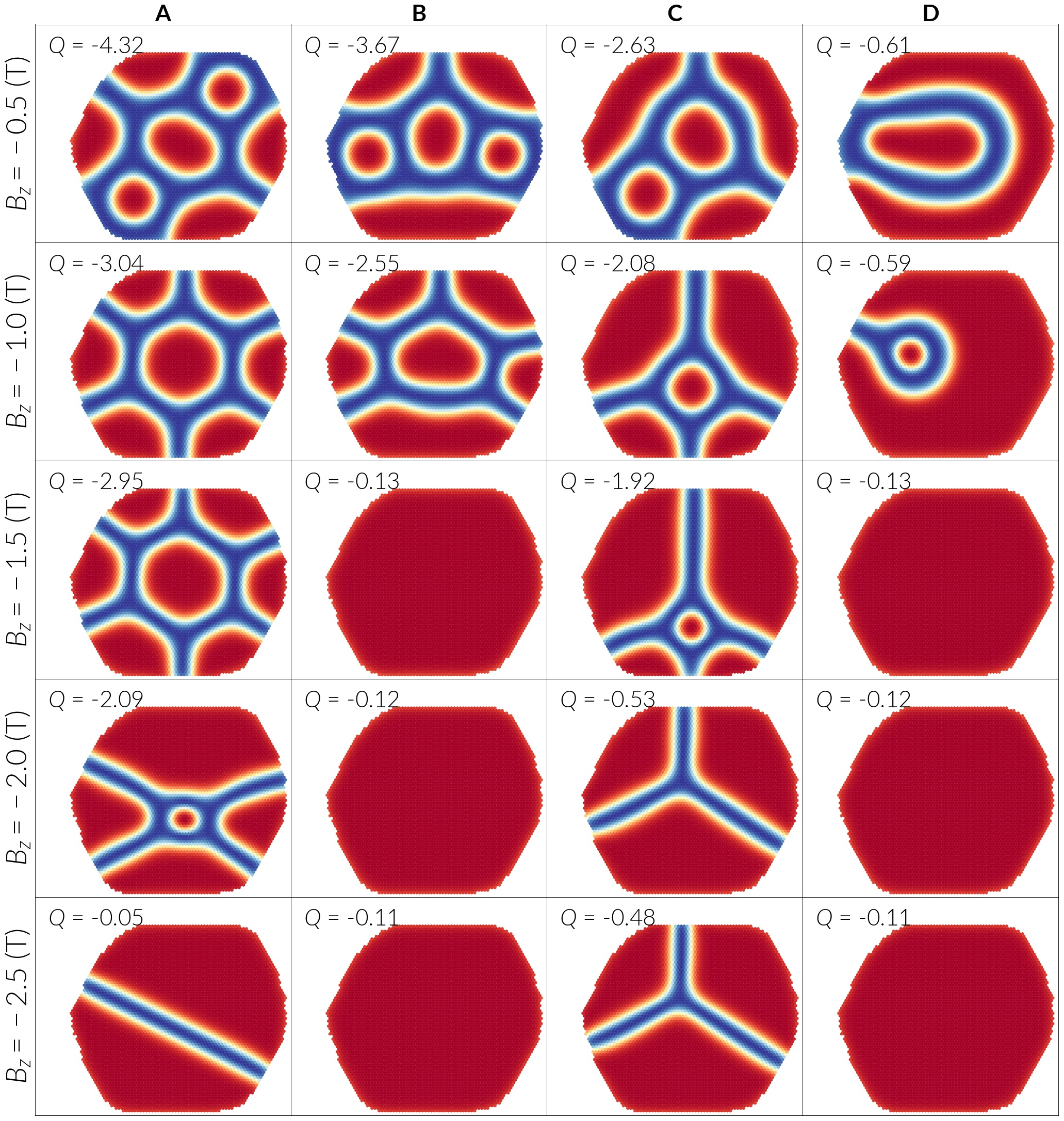
With the aim of devising a reproducible method to obtain the magnetic configurations observed during the field sweep experiment, we replicated this process in our simulations by starting with different initial configurations at strong fields. An adequate choice of initial states is not straightforward since it is often not possible to know every possible equilibrium state. In particular, spin spirals are difficult to specify in simulations because they can manifest as branches, i.e. long domains oriented in the or direction, that bend and extend in any possible direction in the island. Hence, we selected five magnetic states based on a different number of skyrmions and the configuration from experiment of Fig. 1(b) where a skyrmion and a wall coexist next to each other. We do not show results starting from the spiral state of Fig. 1(a) since at sufficiently large fields it turns into a single skyrmion before saturating, and reversing the field it is not possible to obtain the spiral states from the experiments. The reason is that our simulations are performed at zero temperature and we do not consider the tunnel current from the STM tip, which can excite some of the observed states. Nevertheless, simulations show that these spiral configurations are still accessible when choosing an appropriate initial condition, as shown by the simulation of different states (Fig. 1) of the field sweep experiment discussed in Sec. II.
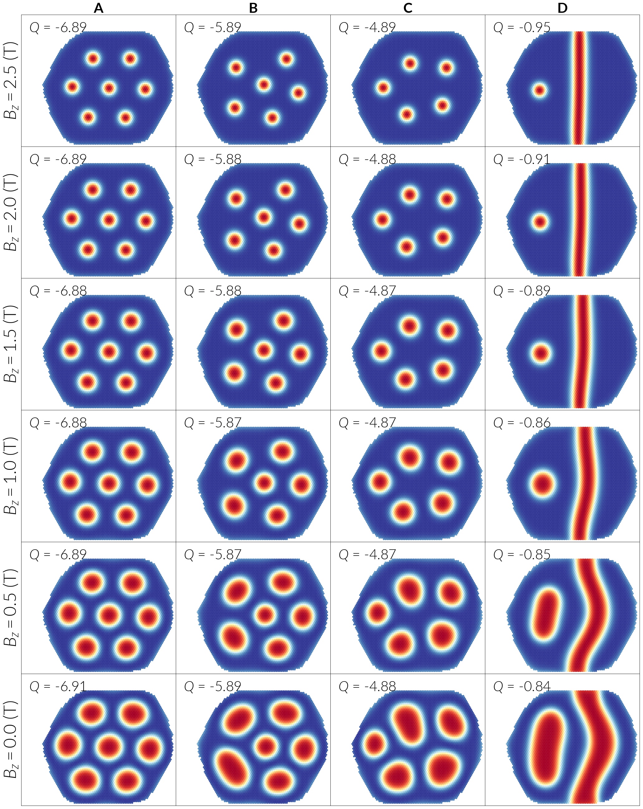
We set our starting point in the field sweep by relaxing these configurations at a magnetic field of , which are the states in the first row of Fig. 4. We characterize them by their topological number , whose absolute value effectively indicates the number of skyrmions in every snapshot. For a spin spiral because it only has spins rotating in a single direction. We then decrease the magnetic field in steps of for every initial state and relax them again, repeating the process down to a field of and registering the resulting configurations under equilibrium for every step. As a result, we obtain the evolution of every initial state given by the columns of Fig. 4 and 5, where we only show snapshots of the relaxed states in steps of . We observe that as we reach zero field, skyrmions expand and occupy a larger area in the sample. When there is a large number of them, as seen in the case of column A of Fig. 4 at zero field, these configurations become more symmetrical in shape because of the restricted available space given by the ferromagnetic background. The topological number of the different magnetic configurations changes only slightly during the magnetic field sweep to T.
When the zero field is crossed, however, we observe interesting magnetic configurations which critically depend on the initial state, see Fig. 5. When we start with different numbers of skyrmions we notice that domains oriented in the direction appear surrounded by elongated domains pointing in the direction in the form of branches whose ends tend to finish perpendicular to the hexagon sides rather than the corners, reminiscent of the magnetic states found experimentally. Indeed, they also show a topological number with the same sign as the applied field, as observed in the experimental data. A plausible explanation for the spirals avoiding the island corners is that, firstly, compared to a straight edge, a corner covers a larger area (about an extra 15% surface if we assume a perfect hexagon) and thus surface effects are stronger and involve an energy cost. Secondly, a spiral sitting at the corner is not optimum as the cycloid needs to rotate and the corner reduces the available space to do this. Finally, the DMI imposes a boundary condition where spins are tilted and orient perpendicular to the island edge surface, making it energetically inefficient to form a spiral at the corner rather than in a smoother surface.
Whereas the phenomenological counting of the topological charge is rather trivial for the magnetic states shown in Fig. 4 where each skyrmion contributes a charge of one, the topological charge of the states in Fig. 5 appears less obvious at first sight. However, by carefully analyzing the magnetic states, we propose a phenomenological model to also estimate the topological charge of such unusual magnetic states. The observed enclosed domains carry a topological charge of since their surrounding domain wall are equivalent to the skyrmion boundary. While some of the skyrmionic structures are partially destroyed at the boundary of the island, the total number of domains in the direction is the same as the initial number of skyrmions, which is evident from columns A-C of Fig. 5 at fields of -0.5 and . As expected, these incomplete skyrmionic domains do not have an integer topological charge and it is possible to roughly estimate this magnitude depending on the domain shape. Incomplete skyrmionic domains sitting in a corner at the boundary of the hexagonal island, which forms a angle, can be identified with because they make a third of a full skyrmionic texture. However, when the domains are more elongated their surrounding domain walls are likely to give a small value. Depending on the flatness of the domain walls, some of these domains can be associated with a charge of .
For example, referring to column A of Fig. 5, at we have three skyrmionic domains which each contribute and four incomplete domains that can be identified with , approximately summing up the total charge of . Furthermore, if we now refer to the state of column C at the same field, we observe elongated boundary domains at the upper sides of the sample with a more straight profile of their surrounding domain walls, but not completely flat. Hence, by only considering the domain at the bottom right of the island as a third of a skyrmion, we obtain a total charge of , being the actual total charge . Similarly, the state from column B at is estimated with . In contrast, the flat profile of the domain wall from the bottom domain of the state of column B, at , makes the contribution of this domain to be zero and hence we estimate a of 3.66 for the whole configuration in the island.
Another way to estimate the magnitudes, is associating the triple junctions from the walls with a charge of . Hence, discarding the boundary contribution, states from the row at in Fig. 5 agree well with this estimation. The slight difference from the spin tilting at the boundaries can contribute up to , as seen in column D at for a uniform ordering in the direction.
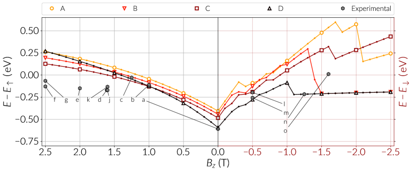
To compare the energy of the states from the experimental field sweep with the configurations obtained from the simulations, we plot the energies of all the configurations as a function of the applied field in Fig. 6, where the field axis follows the order of the sweep process from left to right. Since the field orientation changes in the field sweep process, in the positive field region, shown at the left panel of Fig. 6, the energies are computed with respect to the fully saturated state energy in the direction, . Similarly, at negative fields, we show the energy as a function of the saturated state in the opposite direction, , in the right side of Fig. 6. Energies of the states from the experiment are shown as annotated data points with the labels according to Fig. 1. The four simulated field sweep processes are distinguished in the top legend by the column letter of Fig. 4 and 5. At the center of Fig. 6 we can see that the energy of the zero field spin spiral (data point a) is closest to the zero field state of curve D. This is consistent with the experimental results, where the spin spiral evolves into a skyrmion next to a wall as in Fig. 1(b) and (c), and the energies of these configurations are close to the energies given by curve D of Fig. 6. We can notice a somewhat larger energy in the experimental configurations because the orientation of the spin spiral is different in the experiment. This indicates that the spin spiral prefers to orient perpendicular to a longer or smoother edge of the island. At higher fields the experimental states, which are mainly isolated skyrmions, have a significant lower energy because the simulated configurations have larger regions of spins opposite to the field, which translates into a larger Zeeman energy cost. At negative fields, similar energies are found from the complex spiral configurations of Fig. 1(l) and (m), with the energies of the states in curves C and D at -0.5 T. In particular, the configuration from curve D (Fig. 5 at -0.5 T) resembles Fig. 1m but with the left side of the domain shifted to the right side.
We find that the unusual magnetic states (right plot of Fig. 6) have higher energy than the skyrmion configurations (left plot of Fig. 6), i.e. they are metastable states, which are accessible only at sufficiently low temperatures. In particular, such magnetic field sweeps at low temperature provide access to novel exotic spin textures with non-trivial topological charge. However, while the target state is not a high energy state, it was not observed during neither the experimental nor the simulated magnetic field sweep experiments. Analyzing the resulting magnetic states one can speculate that the edge tilt and the resulting preference of domain walls to be perpendicular to the edges, hinders the formation of a target state.
III Magnetic states in Pd2/Fe/Ir(111) islands
From simulations we will show that, in general, confinement can stabilize target skyrmions at weak fields (roughly below ) in comparison to extended films. However, both the experiments and field sweep simulations for a nanometer-sized island of Pd/Fe on Ir(111) have not been able to produce a target state and analyzing the observed magnetic states suggests that the edge tilt at the boundary might be responsible.
We now turn to a different system, namely a Pd island on a Pd/Fe extended film. Our STM measurements, see Fig. 7, show that the Pd2/Fe island also exhibits a spin spiral state which is modified upon the application of external magnetic fields. The observed modulations on the islands are of magnetic origin, to be precise we attribute them to the non-collinear magnetoresistance effect (NCMR), Hanneken et al. (2015) which is sensitive to changes of the local spin texture: in this case a higher signal (brighter) is observed for smaller angles between nearest neighbor spins, and a lower (darker) signal indicates larger angles between nearest neighbor spins. This means that the in-plane rotations of the spin spiral or the skyrmions appear darker, leading to two dark lines for one spin spiral period and a ring-like feature for each skyrmion (see also Supplemental Material Sec. S2 sup ).
The spin spiral wavelength is about and thus slightly shorter than that of the surrounding Pd/Fe. Importantly, the transition fields to other magnetic states are much higher in the Pd2/Fe, resulting in a situation where at about the Pd2/Fe islands still show complex magnetic order but are surrounded by a fully field-polarized Pd/Fe film. This means that in contrast to the effectively non-magnetic environment of a Pd/Fe island, as in Fig. 1, the boundary condition in the case of a Pd island on a Pd/Fe extended film under the applied magnetic field of 3 T is ferromagnetic.
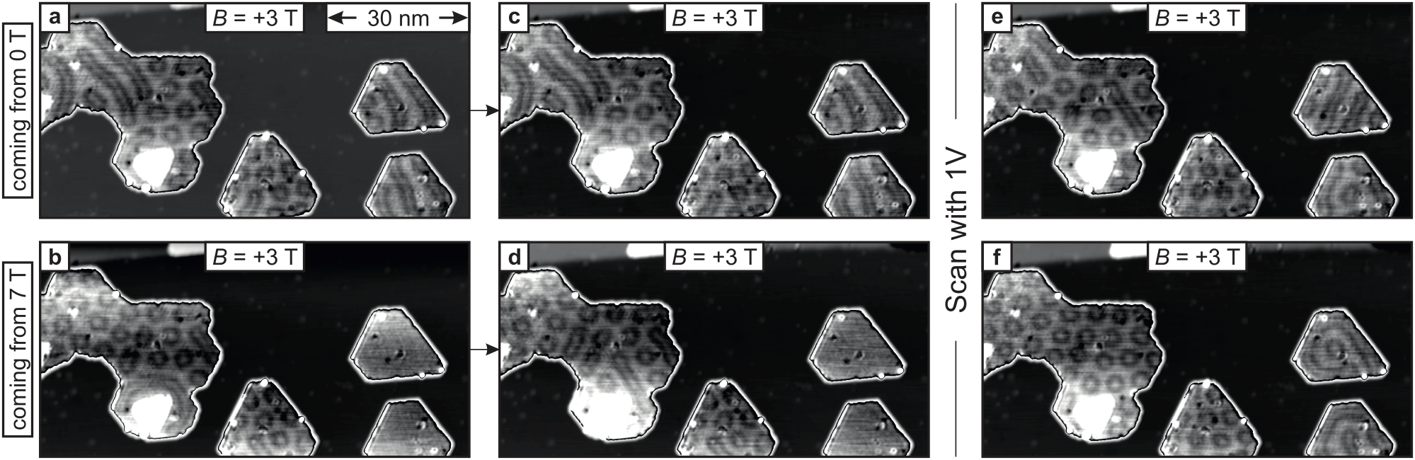
Figures 7(a) and (b) show the same sample area at a magnetic field of , but with a different magnetic field sweep history. Before the measurement shown in Fig. 7(a), the magnetic field was swept up from the virgin state at (see also Supplemental Material Sec. S4 sup ). Figure 7(b), on the contrary, is measured directly after sweeping down the magnetic field from . We observe a hysteretic behavior: during the up-sweep of the external magnetic field we find remainders of the zero-field spin spiral state (a), whereas in the down-sweep the two small islands on the right side of (b) are still in the field-polarized state and the larger islands are dominantly in the skyrmion lattice phase. In both cases small changes can be observed when the area is imaged again, see (c) and (d). We attribute the changes to either a delayed relaxation of the magnetic state towards its thermodynamic equilibrium or a non-negligible influence of the tunnel current of with a bias voltage of .
More significant changes are observed, after the area has been scanned with tunnel parameters of and , see (e) and (f). The application of higher energy tunnel electrons is known to affect the magnetic state of a sample, Romming et al. (2013); Hsu et al. (2016) which is also evident here by a comparison from Fig. 7(c) to (e), and (d) to (f). Now the large island dominantly exhibits a skyrmion lattice in both cases. In the upper right island the larger bias voltage has induced a change of the spin spiral propagation direction from (c) to (e). In the lower right island in (c) and in the case where the same two small islands on the right were in the field-polarized state (d), the tunnel electrons induced target-like states, see (e),(f).
To interpret the target-like states of the small islands in (f) we can start with the outer rim, which we assume to be dominantly parallel to the surrounding field-polarized state of the Pd/Fe extended layer, i.e. the boundary of the island is parallel to the external field. The first dark ring marks the rotation of the spins through the in-plane magnetization to the region where the spins are opposite to the applied field; note that in the upper island this dark ring is not entirely within the island but appears to be pinned to a defect at the island boundary. The second dark ring is another spin rotation through in-plane, meaning that in the center the observed target skyrmion is again parallel to the applied external magnetic field. Comparison with the magnetic states observed in the Pd/Fe island of Fig. 1 with effectively open boundary conditions suggests that the ferromagnetic surrounding is responsible for the generation and stabilization of the target state in the Pd2/Fe islands.
IV Skyrmion and target state stability analysis
To enhance the general understanding on the occurrence of skyrmions and target states in the Pd/Fe and Pd2/Fe islands we perform a systematic simulation based study of hexagons, characterized by their circumradius , where we vary the hexagon size and the out-of-plane applied field . We simulate the Pd2/Fe islands using the same magnetic parameters as the Pd/Fe islands, but changing the boundary conditions to a ferromagnetic rim, according to the discussion in Sec. III. Although a more complete model should account for the phase changes of the Pd/Fe surrounding a Pd2/Fe island at weak fields, a simplified model allows to analyze the effects of modifying the edge condition. This picture is nonetheless accurate enough at stronger fields, where it was shown that the island surrounding is field-polarized. The strategy we employ in the simulations is to start with either a skyrmion or a target state and relax the system with the LLG equation without the precession term, as in Sec. II.2.
IV.1 Size dependence and boundary conditions
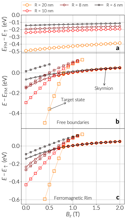
We define islands of sizes from up to in steps of and initialize three magnetic configurations: a skyrmion profile of a radius about 1/4 of the hexagon circumradius, a target state profile of about the size of the island and a ferromagnetic configuration. We firstly compute the energy contribution from the tilted spins at the boundary of the hexagons by subtracting the energy of the fully saturated configuration (in the direction) from the energy of the ferromagnetic state. The former is denoted by and the latter by . We show this result in Fig. 8(a) with the energy differences as a function of the applied field. Results are shown for islands from up to since target states are not stable at . We notice that the boundary energy gain with increasing fields is more pronounced for larger islands.
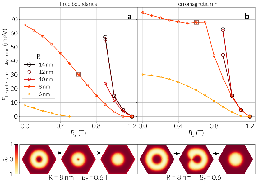
In Fig. 8(b) we calculate the energy of the skyrmion (circle markers) and target state (square markers) configurations with respect to the ferromagnetic state in islands with free boundaries. We compare this result with Fig. 8(c), where we depict the energy of the two states with respect to the ferromagnetic configuration in islands with a ferromagnetic rim. In this case of pinned-spin boundaries, the ferromagnetic state corresponds to the fully saturated state.
From the plots we observe that when ferromagnetic boundaries are present (Fig. 8(c)) the skyrmion has, in general, lower energy than the ferromagnetic state for fields weaker than 1.0 T. In the case of free boundaries (Fig. 8(b)), where the boundary spins decrease the overall energy of the system, for there is a slight shift of the field value below which the skyrmion has lower energy than the uniform state. This effect is more pronounced for smaller (see Supplemental Material, Sec. S10 sup ), where the skyrmion always has larger energy. We also see from Figs. 8(b) and (c) that for and above , the energies of the skyrmion for different start to get closer as the field increases. With free boundaries a small energy difference is present, however with a ferromagnetic rim this difference is unnoticeable, which means skyrmions are not influenced by the spins at the boundary. In the case of free boundaries, the influence of boundary spins vanish for sufficiently strong fields, where the skyrmion size becomes sufficiently small. In Figs. 8(b) and (c) we do not show skyrmion energies for and because skyrmions could not be stabilized and stripe or worm domains appear as the final stable configuration. In this context, the DMI dominates over the Zeeman interaction, and a larger island size means confinement effects on the magnetic configuration are weaker.
Regarding target states, the critical field below which target states have smaller energy than the ferromagnetic state, depends more critically (steeper energy curves) on the hexagon size than in the skyrmion case, owing to the larger number of non-collinear spins and thus, a larger influence of the DMI energy. The range of fields where boundary spins do not have an influence is substantially smaller than in the skyrmion case, which is only noticed for the case of a ferromagnetic rim close to a field of . Furthermore, target states are more affected by the available space in the island since for free boundaries, at small hexagon sizes, , a target state is observed up to a field of 0.5 T, whereas this critical field is close to the field where target states cannot be stabilized, which is around , when ferromagnetic boundaries are present.
A comparison of the energy of skyrmions and target states reveals that with free boundaries target states have always larger energy than skyrmions up to sizes of around . In contrast, with a ferromagnetic rim target states have lower energy than skyrmions at and possibly become the ground state of the system at a critical field. This supports the hypothesis that confinement has a larger influence on target states, most likely because of the DMI energy and the repulsion from the boundary spins, which is weaker for a ferromagnetic rim. Additionally, we see that at skyrmions turn into worm or stripe domains below , however target states are stable down to zero field since their double spin rotation allows them to cover a larger area without distortion.
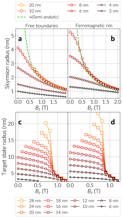
Similar to the behaviour of isolated skyrmions in extended systems, by increasing the magnetic field strength the skyrmion size decreases. To quantify this change we calculated the skyrmion radius as a function of the magnetic field for hexagon sizes between 3 and and different boundary conditions. This result is depicted in Fig. 9(a) and (b). We define the skyrmion radius as the distance from the skyrmion center to the ring where . In the case of , the curve is not shown below certain field magnitudes since the system relaxed into elongated domains or spiral domains. To compare the effect of the confinement on the skyrmions with the skyrmion size in extended samples, we additionally plot in Fig. 9(a) and (b), as a dashed line, an estimation of the skyrmion radius as a function of the magnetic field, based on the continuum theory proposed in Ref. Wang et al., 2018, which depends on the skyrmion radius and the width of the wall separating the skyrmion core from the ferromagnetic background. This semi-analytical result (from equations 11 and in Ref. Wang et al., 2018) slightly underestimates the skyrmion radius Wang et al. (2018), in part because it assumes the skyrmion radius is much larger than the width of its enclosing wall, nevertheless it correctly reproduces the skyrmion size dependence with and agrees reasonably well with the skyrmion sizes shown in Ref. Romming et al., 2015. For hexagon sizes below 8 nm and sufficiently small fields, we notice that skyrmions in the system with a ferromagnetic rim (Fig. 9(a)) are larger in size than the skyrmions in the sample with free boundaries (Fig. 9(b)) at equivalent field strengths and . The reason is that for sufficiently weak applied fields the skyrmion tries to occupy the largest possible area in the island and when the island has free boundaries the tilted spins at the hexagon edges restrict the skyrmion size (see Supplemental Sec. S11 sup ), as shown in Fig. 9(a). This is in contrast to the system of Fig. 9(b), where pinned spins at the boundary do not limit the skyrmion and allow it to expand further towards the sample edges. When increasing the field strength skyrmions shrink, hence for sufficiently large sample size and applied field the boundary spins no longer have an influence on the skyrmion and their sizes converge to similar values regardless of the edge condition, as shown by a comparison with the theoretical curve. Moreover, we observe that with a ferromagnetic rim the skyrmion size behaves as in an extended film in a larger range of magnetic fields for hexagon sizes as small as 4 nm and, in particular, for islands with around . The influence of the boundary on the skyrmion size is in agreement with the skyrmion energies of Fig. 8, thus we can say that confinement effects on a single skyrmion are important at sufficiently weak fields for hexagonal islands of , and are stronger in islands with free boundaries.
We define the target state radius as the outermost distance where and we plot it as a function of hexagon size and magnetic field in Fig. 9(c) and (d). An analysis of the radius of target states in hexagons with different boundary conditions results in the same tendency exhibited by skyrmions, i.e. target states become smaller with increasing field magnitudes and are larger in size when spins are not tilted at the sample edges. However, target states are, overall, noticeable bigger than skyrmions for hexagon radii up to and below the critical field of 1.2 T where they become unstable. Target states can be stabilized in hexagons as small as , where they are stable in a larger range of field magnitudes when a ferromagnetic rim is present (Fig. 9(d)). Below this circumradius the system relaxes to a skyrmion for the two boundary conditions. Furthermore, a critical magnetic field is observed at , where the size of target states in islands larger than converges to a radius around , and the configuration becomes small and well confined within the island. By increasing the field, the radius of target states tend to a similar value, smaller than , independent of the system size.
IV.2 Phase diagram
As observed in experimentally measured islands, spin spiral configurations are the most probable ground state of the system at weak fields. This is illustrated, in part, in Fig. 3, where the data point for the state from Fig. 1(a) has the lowest energy at zero field. Furthermore, the favored formation of spirals at weak fields is expected from the material parameters (see Sec. II.1), which specify a critical DMI value Rohart and Thiaville (2013); Mulkers et al. (2016) of , thus . Since the DMI magnitude is well above the critical value, spiral solutions are energetically favored, as can be seen in Figs. 1 and 10(a).
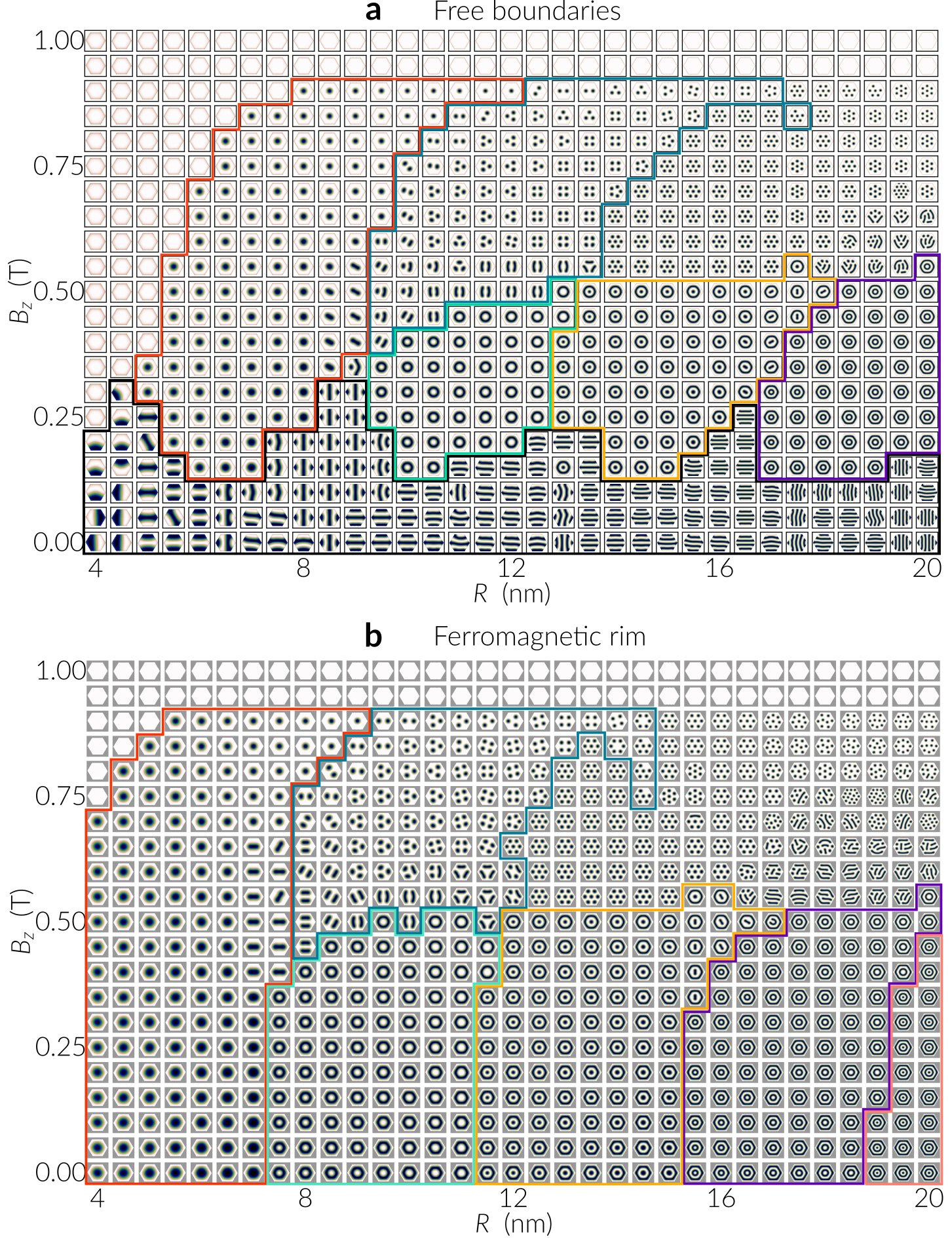
At larger field values, spin spirals are no longer favored and skyrmionic textures are candidates for being the ground state. In Fig. 10 we show full phase diagrams depicting the lowest energy state of hexagons as a function of the circumradius , the applied field and the two different boundary conditions. The lowest energy configurations were found by simulating 27 different initial states per point in the diagram, which correspond to multiple skyrmion states up to a number of seven, -skyrmion states from up to , random configurations, domain walls and skyrmions next to a wall.
The results illustrated in Fig. 10(a) at zero field, for hexagons with free boundaries, confirm our observations of spin spirals as ground states. The number of cycloids of these lowest energy spirals, fitting within an island, depends on the island size, which is consistent with Ref. Mulkers et al., 2016, and their period remains constant since, for example, islands with and 12 nm have twice and three times, respectively, the number of cycloids than the case . Additionally, they do not seem affected by the applied field. By increasing the field, between and , at the top left enclosed region we distinguish a single skyrmion phase. The transition from spirals into single skyrmion states is clearly dependent on the Zeeman interaction which starts to dominate over the DMI.
Next to the single skyrmion region, at sufficiently large magnetic fields, we marked the area where worm domains or up to 6 multiple skyrmions become the lowest energy state. At the right of this region, a larger number of skyrmions are the lowest energy configurations. Since we specified up to seven skyrmions as initial states, it is likely that a slightly larger number of skyrmions have lower energy in this region. For example, at and we notice a state with 12 skyrmions and 2 half-skyrmions, whose topological charge is about -12.6. Multiple skyrmion states are favored as the island size and applied field increase because there is enough distance to avoid the inter-skyrmion repulsion that can overcome the energy barrier from the boundary. The optimal arrangement of skyrmions fitting within an island clearly follows a close packing ordering of congruent circles, as has been discussed in Ref. Zhao et al., 2016 for the case of disks, and the system size affects the number of confined skyrmions, Beg et al. (2015); Zhao et al. (2016); Pepper et al. (2018); Ho et al. (2019) which can be characterized by the total topological charge. Furthermore, the shape of the magnetic structures usually become distorted at the phase boundaries, in particular skyrmions, which appear as worm domains. These phase transitions are driven by (i) the hexagonal shape of the island, (ii) the interplay of the DMI and the Zeeman interaction when the field changes (i.e. along the vertical axis of Fig. 10), as in the case of a skyrmion in Fig. 3, and (iii) by the size of the island.
Below the skyrmion regions, at lower magnetic fields and with increasing hexagon radii, target states, -skyrmion and -skyrmion states have the lowest energy as the DMI energy is more dominant than the Zeeman energy and there is enough available space for these states. In this context, for sufficiently large island sizes there is a possibility that more complex configurations such as multiple target states and so-called skyrmion bags Foster et al. (2019); Rybakov and Kiselev (2019) have lower energy. Interestingly, we observed a few of these states during our energy minimization process and none of them had lower energy than the states obtained from our set of initial states.
At fields above the ferromagnetic state is always the ground state. At weaker fields and when the hexagon radii are smaller than 8 nm, a region is observed where the uniform state is the lowest energy configuration because boundary spins inhibit the formation of skyrmions.
When ferromagnetic boundaries are present spin spirals are suppressed and the phases of skyrmionic textures significantly expand and are observed down to zero field, as shown in Fig. 10(b). In particular, a single skyrmion becomes the ground state for islands down to radius in size. Furthermore, because of the lack of tilted boundary spins, close to , a phase emerges with -skyrmion configurations. In agreement with the case of open boundaries, the saturation field remains 0.9 T. In this case, the region where the uniform state is the ground state, for fields below , is smaller than in the case of open boundaries and confirms that the tilted spins at the edge hinder the formation of skyrmions in sufficiently small hexagons.
In Fig. 8 we saw that for hexagons with a radius around , a ferromagnetic rim causes target states to have smaller energy than skyrmions for fields below T. From Fig. 10(b) we notice that in islands with a ferromagnetic rim the target state becomes the lowest energy state in a region of hexagon radii from approximately 7.5 nm up to 11 nm and below fields of 0.5 T, and hence it is energetically favored in this region of phase space. Furthermore, since the islands measured experimentally have a radius of about 9 nm we can infer that target states in Pd2/Fe islands have a larger probability of being observed if the system overcomes energy barriers towards lowest energy configurations.
IV.3 Stability of skyrmions and target states
A method for the estimation of the stability of skyrmions is the calculation of energy barriers separating them from other equilibrium states, in particular from the uniform state. Two known mechanisms Cortés-Ortuño et al. (2017); Stosic et al. (2017); Bessarab et al. (2015, 2018) for the skyrmion annihilation (creation) are the skyrmion collapse (emergence) and the skyrmion escape (nucleation) mediated by the boundary. The latter is only possible when free boundaries are present.
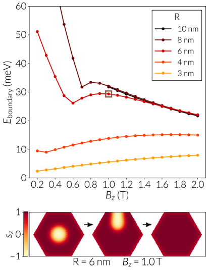
In Fig. 11 we show the energy barriers between the skyrmion and the uniform state via the escape mechanism for the system with open boundaries. To obtain this transition, we initialized the algorithm by moving the skyrmion towards the upper boundary of the hexagon. In the figure we observe that for the height of the barrier increases with larger field strengths, and for we see the opposite tendency. Furthermore, for and fields there is a drastic change in the slope of the curve because the skyrmion elongates towards a boundary until reaching the sample border and starts escaping, instead of displacing without deformation towards the sample edge, as occurs for sufficiently large fields. In small samples the effect is unnoticed since the skyrmion is directly touching the sample boundaries, thus it can easily transition towards the uniform state. Snapshots of these transitions for an hexagon and energy bands from the simulations are shown in Sec. S12 of the Supplemental Material. sup
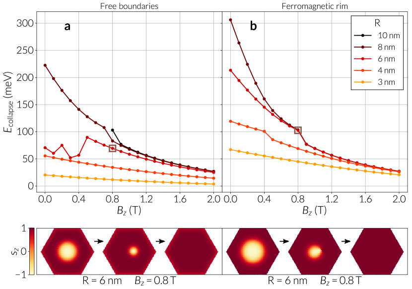
Regarding the collapse mechanism, we summarize the energy barrier calculations in Fig. 12, for the two boundary conditions. In this case we notice the barriers of hexagons with free boundaries Fig. 12(a)) are smaller in magnitude than the corresponding barriers from the system with ferromagnetic boundaries (Fig. 12(b)). Additionally, in Fig. 12(a) at and below the algorithm finds a different energy path, which is mediated by the boundary and is not allowed when the system has fixed spins at the boundary. The change in the curve around for circumradius above indicate the collapse of the skyrmion through a singularity, Cortés-Ortuño et al. (2017) which is not present at larger magnetic fields or in small sample sizes since the singularity is defined in a few atomic spaces. For the hexagon with the ferromagnetic rim there are no effects from the boundary, however singularities still appear at sufficiently large samples or skyrmion sizes, which can be seen from the small jumps in the curves of Fig. 12(b). According to these results, it is possible that the boundary has an influence on the formation of a singularity for large enough hexagons. For fields below and circumradius of and above, we do not show data points since the system relaxes into an elongated skyrmionic domain or spiral domain.
An investigation of the transition energies of target states into skyrmions can provide us an alternative answer for the problem of stability of target states. We computed this transition for different hexagon sizes and boundary conditions and summarize the results in Fig. 13. From the simulations with we observe that the minimum energy path is given by the collapse of the inner core of the target state, which is oriented along the field direction , making the ring of spins in the direction to expand into the skyrmion centre (see Supplemental Fig. S13 sup ). The same mechanism has been reported by Hagemeister et al. Hagemeister et al. (2018) in infinite samples. When the system has free boundaries, other possible energy paths for the target state involve the boundaries of the hexagon and during this process complex spiral orderings mediate the transition. Unfortunately, our attempts to calculate transitions from target states to either a ferromagnetic state or a skyrmion, via the boundary of the system, were not successful owing to the lack of convergence of the algorithm to a consistent result, thus a study of these paths requires a more careful analysis.
The inner collapse transitions are given by the smooth curves of Fig. 13. An exception occurs for , and ferromagnetic boundaries (Fig. 13(b)), since the transition in those cases is given by the emergence of a singularity at the ring of spins (see Supplemental Fig. S14 sup ). The reason is that the target state is larger in size when a ferromagnetic rim is present, as we saw in Fig. 9, which must be around a critical size for singularities to mediate the transition, as in the case of the skyrmion collapse. The same effect occurs for and weak fields for the two boundary conditions, hence the algorithm did not converge to an optimal path for fields below . The energy barrier calculations indicate that target states have associated larger barriers to decay into the skyrmion state in hexagons with a ferromagnetic rim. Moreover, the most evident mechanism for the annihilation of the target state is through a collapse or a disruption mediated by a singularity, since boundary effects are forbidden. Although there are possibly multiple other energy paths for the annihilation of a target state, for example the transition of a target state into more than one skyrmion, they are likely to have associated larger energy barriers because multiple singularities would be necessary to mediate these transitions. These results suggest that the transition path of a target state into a single skyrmion is the shortest in energy landscape and with the highest probability to occur.
V Discussion
Using (spin-polarized) scanning tunneling microscopy we have studied the magnetic properties of two different systems, namely Pd/Fe and Pd2/Fe on Ir(111), in a confined geometry. We find that the investigated islands host a variety of spin textures, including different metastable states. In islands with an effectively non-magnetic surrounding the spin texture exhibits a tilt at the edges. A strong hysteresis is observed in magnetic field dependent measurements, where the virgin curve magnetic states are qualitatively different from the ones obtained when the magnetic field is subsequently applied in the opposite direction: whereas in the first case magnetic skyrmions are found, in the latter case the magnetic states are characterized by branched walls which end at island boundaries. When the surrounding of an island is ferromagnetic, such walls perpendicular to island edges are avoided and target-like configurations can be found.
Using discrete spin simulations we can reproduce our experimental observations of multiple chiral configurations in small Pd/Fe islands. An analysis of the energy of chiral textures, which include the skyrmion, the target state and the -skyrmion, indicates that these configurations can be stabilized from zero field up to different critical field magnitudes. Moreover, from the energy curves of these configurations as a function of the applied field, it can be inferred that the stability of some configurations can be explained by measuring the energy barriers separating them from energetically close configurations, for example a target state with a skyrmion. These results can be used as a reference for the observation of these magnetic states in future experiments. In particular, there is still a lack of experimental evidence of the -skyrmion in a small confined system with interfacial DMI.
In order to reproduce different magnetic textures from SP-STM images of a field sweep experiment on Pd/Fe islands, we performed field sweep simulations in a range of field magnitudes smaller than the one used in the experiment and using specific initial states based on different numbers of skyrmions. Our simulation results showed multiple skyrmion-like domains trapped within branched spiral states that appear when the direction of the field is inverted after crossing the zero field point, and we provided arguments to identify them by their topological number. The field magnitudes for the observation of chiral structures in our simulations differ from the ones in experiments because simulations are performed at zero temperature without any other external excitations such as the ones generated by the tunnel electrons in SP-STM. Accordingly, we did not exactly reproduce the results from the experiment, nonetheless it was still possible to stabilize most of the observed magnetic structures from the different field stages. Our simulations show that all the observed magnetic configurations should be accessible through an appropriate excitation of the system, thus further evidence of target states or -skyrmions could be obtained in future experimental studies.
Using our simulations of a field sweep process it was not possible to obtain a target state from spiral configurations but mostly skyrmions from domain walls at increasing strong field magnitudes (above ) or large abrupt field changes. A possible solution to obtain these axially symmetric configurations with the field sweep method is specifying a suitable initial state, however this might be difficult in practice.
We performed a thorough analysis of skyrmions and target states under different conditions, by varying the size, applied field and boundary conditions of perfectly shaped hexagons. The main motivation for the modification of the boundary condition was the observation of a target-like state in the Pd2/Fe islands on Ir(111), where the surrounding of the islands is ferromagnetic. Simulations of hexagonal islands of this material showed that for sufficiently small systems, skyrmions and target states in islands with a ferromagnetic rim have lower energy than the uniform state in a broader range of magnetic fields. In particular, for islands with radii around , target states have lower energy than skyrmions when a ferromagnetic boundary is present.
In hexagons with free boundaries, we found that for radii up to approximately and fields below , the tilting of spins at the island rim decreases the DMI energy and affects the skyrmion structure, by decreasing the skyrmion size in comparison to hexagons with a ferromagnetic rim.
In contrast, due to the lack of canted spins at the island rim when ferromagnetic boundaries are present, skyrmions and target states are, in general, larger in size compared to hexagons with open boundaries. We observe that this larger size had an influence on the energy barriers separating the skyrmion from the ferromagnetic ordering and the target state from the skyrmion, making the barriers larger in systems with a ferromagnetic rim.
To gain an understanding of the lowest energy states of the hexagon systems we computed a full phase diagram illustrating regions in hexagon radius and applied field space with the possibly lowest energy configurations; there is no guarantee that other complex magnetic states that could not be mapped with our method can have lower energy. On the other hand, our random set of states showed that other configurations beyond -skyrmions are usually highly energetic, thus finding the true ground states requires a dedicated analysis that goes beyond the scope of this work. We confirmed that spin spiral configurations are the lowest energy states at weak fields and we identified regions where multiple -skyrmion states are the lowest energy states at sufficiently large island sizes and applied fields. From the comparison of the energies of target states and skyrmions at hexagon sizes around , we confirm that target states become the lowest energy states when a ferromagnetic rim is present, supporting our experimental observations of the favored stabilization of target states in Pd2/Fe islands.
Furthermore, by analyzing minimum energy paths we found that in hexagons with free boundaries, up to fields of approximately 1.6 T and for hexagon circumradii above , the minimum energy path between skyrmions and the uniform ordering is via the boundary, which is consistent with recent studies. Cortés-Ortuño et al. (2017); Stosic et al. (2017); Bessarab et al. (2018) A ferromagnetic rim inhibits a skyrmion and a target state to escape through the boundary, hence forcing them to transition by a collapse or by a singularity. At weak fields and sufficiently large sizes these transitions have an energy barrier significantly larger than an escape mediated by the boundary when spins are not pinned at the island edges. Moreover, early results have shown that with free boundaries a target state can also transition at the boundary through spiral configurations. For instance, a lollipop-like state is formed when a target state reaches the sample edge and a single wall emerges when half of the target state has escaped. These configurations are energetically favored at weak magnetic fields and as we saw in the simulated field sweep process, they tend to stabilize with branches perpendicular to the sample edges. These arguments indicate that skyrmions and target states should be more stable in islands with ferromagnetic boundaries since there is a larger energy cost for these structures to transition into other accessible states in the energy landscape. In this context, a more detailed insight into the lifetime of the observed configurations would require the calculation of transition rates, as in Ref. von Malottki et al., 2019. Furthermore, an accurate model of these solutions could be obtained in the future using effective magnitudes for the material parameters of Pd2/Fe/Ir(111). For example, recently Refs. Dupé et al., 2014; Bouhassoune et al., 2019 have reported magnitudes from ab initio calculations.
VI Conclusions
In summary, in this work we have performed SP-STM measurements of skyrmionic textures in Pd/Fe and Pd2/Fe islands on Ir(111) and we have employed discrete spin simulations to analyze our experimental observations. Our results show that discrete spin simulations can accurately explain our experimental findings. Furthermore, by modelling hexagonally shaped islands we provide a more general understanding of how the applied field, system size and boundary conditions affect the stability of skyrmions and target states in confined geometries with interfacial DMI. In particular, we found that the presence of ferromagnetic boundaries favor the stability of target states in a region of applied field and island size that explains the experimental observation of a target-like state in Pd2/Fe/Ir(111) islands. In addition, simulations predict conditions for the stability of novel magnetic configurations, such as -skyrmions, that could be experimentally observed in the future.
We believe that the ease to carry out multiple computer simulated experiments can help for the future design of energy efficient spintronic devices based on small confined DMI systems, such as bit patterned recording media, where skyrmions or target states would encode the memory bits.
VII Acknowledgments
We acknowledge financial support from CONICYT Chilean scholarship programme Becas Chile (72140061), the EPSRC Complex Systems Simulations DTC (EP/G03690X/1), the EPSRC Programme grant on Skyrmionics (EP/N032128/1), the Horizon 2020 European Research Infrastructure project OpenDreamKit (67 6541), and by the Deutsche Forschungsgemeinschaft (DFG, German Research Foundation) - 402843438; SFB668-A8.
The simulation data for a complete reproduction of this work can be found in Ref. Cortés-Ortuño et al., 2019.
References
- Bogdanov et al. (1989) A. N. Bogdanov, M. V. Kudinov, and D. A. Yablonskii, Sov. Phys. Solid State 31, 1707 (1989).
- Bogdanov and Yablonskii (1989) A. Bogdanov and D. Yablonskii, Zh. Eksp. Teor. Fiz 95, 178 (1989).
- Rößler et al. (2006) U. K. Rößler, A. N. Bogdanov, and C. Pfleiderer, Nature 442, 797 (2006).
- Mühlbauer et al. (2009) S. Mühlbauer, B. Binz, F. Jonietz, C. Pfleiderer, A. Rosch, A. Neubauer, R. Georgii, and P. Böni, Science 323, 915 (2009).
- Heinze et al. (2011) S. Heinze, K. von Bergmann, M. Menzel, J. Brede, A. Kubetzka, R. Wiesendanger, and G. B. S. Blügel, Nature Physics 7, 713 (2011).
- Romming et al. (2013) N. Romming, C. Hanneken, M. Menzel, J. E. Bickel, B. Wolter, K. von Bergmann, A. Kubetzka, and R. Wiesendanger, Science 341, 636 (2013).
- Romming et al. (2015) N. Romming, A. Kubetzka, C. Hanneken, K. von Bergmann, and R. Wiesendanger, Phys. Rev. Lett. 114, 177203 (2015).
- Wiesendanger (2016) R. Wiesendanger, Nature Reviews Materials 1, 16044 (2016).
- Bogdanov and Hubert (1994a) A. Bogdanov and A. Hubert, Journal of magnetism and magnetic materials 138, 255 (1994a).
- Bogdanov and Hubert (1999) A. Bogdanov and A. Hubert, Journal of Magnetism and Magnetic Materials 195, 182 (1999).
- Rohart and Thiaville (2013) S. Rohart and A. Thiaville, Physical Review B 88, 184422 (2013).
- Leonov et al. (2014) A. O. Leonov, U. K. Rößler, and M. Mostovoy, in EPJ Web of Conferences, Vol. 75 (EDP Sciences, 2014) p. 05002.
- Beg et al. (2015) M. Beg, R. Carey, W. Wang, D. Cortés-Ortuño, M. Vousden, M.-A. Bisotti, M. Albert, D. Chernyshenko, O. Hovorka, R. L. Stamps, and H. Fangohr, Scientific Reports 5, 17137 (2015).
- Liu et al. (2015) Y. Liu, H. Du, M. Jia, and A. Du, Physical Review B 91, 094425 (2015).
- Carey et al. (2016) R. Carey, M. Beg, M. Albert, M.-A. Bisotti, D. Cortés-Ortuño, M. Vousden, W. Wang, O. Hovorka, and H. Fangohr, Applied Physics Letters 109, 122401 (2016).
- Pepper et al. (2018) R. A. Pepper, M. Beg, D. Cortés-Ortuño, T. Kluyver, M.-A. Bisotti, R. Carey, M. Vousden, M. Albert, W. Wang, O. Hovorka, and H. Fangohr, Journal of Applied Physics 123, 093903 (2018).
- Kolesnikov et al. (2018) A. G. Kolesnikov, M. E. Stebliy, A. S. Samardak, and A. V. Ognev, Scientific Reports 8, 16966 (2018).
- Hagemeister et al. (2018) J. Hagemeister, A. Siemens, L. Rózsa, E. Y. Vedmedenko, and R. Wiesendanger, Physical Review B 97, 174436 (2018).
- Shen et al. (2018) M. Shen, Y. Zhang, J. Ou-Yang, X. Yang, and L. You, Applied Physics Letters 112, 062403 (2018).
- Li et al. (2018) S. Li, J. Xia, X. Zhang, M. Ezawa, W. Kang, X. Liu, Y. Zhou, and W. Zhao, Applied Physics Letters 112, 142404 (2018).
- Komineas and Papanicolaou (2015a) S. Komineas and N. Papanicolaou, Physical Review B 92, 064412 (2015a).
- Komineas and Papanicolaou (2015b) S. Komineas and N. Papanicolaou, Physical Review B 92, 174405 (2015b).
- Zhang et al. (2016) X. Zhang, J. Xia, Y. Zhou, D. Wang, X. Liu, W. Zhao, and M. Ezawa, Physical Review B 94, 094420 (2016).
- Nagaosa and Tokura (2013) N. Nagaosa and Y. Tokura, Nature nanotechnology 8, 899 (2013).
- Finazzi et al. (2013) M. Finazzi, M. Savoini, A. R. Khorsand, A. Tsukamoto, A. Itoh, L. Duò, A. Kirilyuk, T. Rasing, and M. Ezawa, Physical Review Letters 110, 177205 (2013).
- Zhang et al. (2018) S. Zhang, F. Kronast, G. van der Laan, and T. Hesjedal, Nano Letters 18, 1057 (2018).
- Zheng et al. (2017) F. Zheng, H. Li, S. Wang, D. Song, C. Jin, W. Wei, A. Kovács, J. Zang, M. Tian, Y. Zhang, H. Du, and R. E. Dunin-Borkowski, Physical Review Letters 119, 197205 (2017).
- Jin et al. (2017) C. Jin, Z.-A. Li, A. Kovács, J. Caron, F. Zheng, F. N. Rybakov, N. S. Kiselev, H. Du, S. Blügel, M. Tian, et al., Nature Communications 8 (2017), doi:10.1038/ncomms15569.
- Ho et al. (2019) P. Ho, A. K. Tan, S. Goolaup, A. G. Oyarce, M. Raju, L. Huang, A. Soumyanarayanan, and C. Panagopoulos, Phys. Rev. Applied 11, 024064 (2019).
- Fert et al. (2017) A. Fert, N. Reyren, and V. Cros, Nature Reviews Materials 2, 1 (2017).
- Bessarab et al. (2015) P. F. Bessarab, V. M. Uzdin, and H. Jónsson, Computer Physics Communications 196, 1 (2015).
- Cortés-Ortuño et al. (2017) D. Cortés-Ortuño, W. Wang, M. Beg, R. A. Pepper, M.-A. Bisotti, R. Carey, M. Vousden, T. Kluyver, O. Hovorka, and H. Fangohr, Scientific Reports 7, 4060 (2017).
- Stosic et al. (2017) D. Stosic, J. Mulkers, B. Van Waeyenberge, T. B. Ludermir, and M. V. Milošević, Physical Review B 95, 214418 (2017).
- Bessarab et al. (2018) P. F. Bessarab, G. P. Müller, I. S. Lobanov, F. N. Rybakov, N. S. Kiselev, H. Jónsson, V. M. Uzdin, S. Blügel, L. Bergqvist, and A. Delin, Scientific Reports 8, 3433 (2018).
- Wiesendanger (2009) R. Wiesendanger, Rev. Mod. Phys. 81, 1495 (2009).
- (36) See Supplemental Material.
- Hanneken et al. (2015) C. Hanneken, F. Otte, A. Kubetzka, B. Dupé, N. Romming, K. von Bergmann, R. Wiesendanger, and S. Heinze, Nature Nanotechnology 10, 1039 (2015).
- Bisotti et al. (2018) M.-A. Bisotti, D. Cortés-Ortuño, R. Pepper, W. Wang, M. Beg, T. Kluyver, and H. Fangohr, Journal of Open Research Software 6, 22 (2018).
- Leonov et al. (2016) A. O. Leonov, T. L. Monchesky, N. Romming, A. Kubetzka, A. N. Bogdanov, and R. Wiesendanger, New Journal of Physics 18, 065003 (2016).
- Lobanov et al. (2016) I. S. Lobanov, H. Jónsson, and V. M. Uzdin, Physical Review B 94, 174418 (2016).
- Wang et al. (2018) X. S. Wang, H. Y. Yuan, and X. R. Wang, Communications Physics 1, 31 (2018).
- von Malottki et al. (2017) S. von Malottki, B. Dupé, P. F. Bessarab, A. Delin, and S. Heinze, Scientific Reports 7, 12299 (2017).
- Kiselev et al. (2011) N. S. Kiselev, A. N. Bogdanov, R. Schäfer, and U. K. Rößler, Journal of Physics D: Applied Physics 44, 392001 (2011).
- Berg and Lüscher (1981) B. Berg and M. Lüscher, Nuclear Physics, Section B 190, 412 (1981).
- Yin et al. (2016) G. Yin, Y. Li, L. Kong, R. K. Lake, C. L. Chien, and J. Zang, Physical Review B 93, 174403 (2016).
- Bogdanov and Hubert (1994b) A. Bogdanov and A. Hubert, physica status solidi (b) 186, 527 (1994b).
- Hsu et al. (2016) P.-J. Hsu, A. Kubetzka, A. Finco, N. Romming, K. von Bergmann, and R. Wiesendanger, Nature Nanotechnology 12, 123 (2016).
- Mulkers et al. (2016) J. Mulkers, M. V. Milošević, and B. Van Waeyenberge, Phys. Rev. B 93, 214405 (2016).
- Zhao et al. (2016) X. Zhao, C. Jin, C. Wang, H. Du, J. Zang, M. Tian, R. Che, and Y. Zhang, Proceedings of the National Academy of Sciences 113, 4918 (2016).
- Foster et al. (2019) D. Foster, C. Kind, P. J. Ackerman, J.-S. B. Tai, M. R. Dennis, and I. I. Smalyukh, Nature Physics (2019), 10.1038/s41567-019-0476-x.
- Rybakov and Kiselev (2019) F. N. Rybakov and N. S. Kiselev, Phys. Rev. B 99, 064437 (2019).
- von Malottki et al. (2019) S. von Malottki, P. F. Bessarab, S. Haldar, A. Delin, and S. Heinze, Phys. Rev. B 99, 060409(R) (2019).
- Dupé et al. (2014) B. Dupé, M. Hoffmann, C. Paillard, and S. Heinze, Nature Communications 5, 4030 (2014).
- Bouhassoune et al. (2019) M. Bouhassoune, I. L. Fernandes, S. Blügel, and S. Lounis, arXiv e-prints , arXiv:1901.07029 (2019).
- Cortés-Ortuño et al. (2019) D. Cortés-Ortuño, N. Romming, M. Beg, K. von Bergmann, A. Kubetzka, O. Hovorka, H. Fangohr, and R. Wiesendanger, “Data set for: Nano-scale magnetic skyrmions and target states in confined geometries,” Zenodo doi:10.5281/zenodo.1438396. Github: https://github.com/davidcortesortuno/paper-2019_nanoscale_skyrmions_target_states_confined_geometries (2019).