Optical bistability in a -type atomic system including near dipole-dipole interaction
Abstract
The advantage of optical bistability (OB) using three-level electromagnetically induced transparency (EIT) atomic system over the two-level system is its controllability, as absorption, dispersion, and optical nonlinearity in one of the atomic transitions can be modified considerably by the field interacting with nearby atomic transitions. This is due to induced atomic coherences generated in such EIT system. The inclusion of near dipole-dipole (NDD) interaction among atoms further modifies absorption, dispersion, and optical nonlinearity of three-level EIT system and the OB can also be controlled by this interaction, producing OB to multistability.
keywords:
Optical bistability, electromagnetically induced transparency, near dipole-dipole interactions, three-level atomPACS:
42.50.Ct; 42.50.Gy; 42.65.Pc1 Introduction
Atomic optical bistability (AOB) is a phenomenon that exploits both the cooperative nature of the interaction between a group of atoms with the field and its strong nonlinearity. The essential element in AOB is the nonlinear relation between the applied electromagnetic field and the electromagnetic field that is radiated by the atomic dipoles, when the actions of all the other dipoles are taken into account. Cooperative radiation therefore plays a key role in bistability [1].
The optical bistability (OB) in an ensemble of two-level atomic systems contained inside an optical cavity has been extensively studied in the decade of eighties and early years of nineties. The studies were focused mainly on to utilize the phenomenon of OB in optical memories, optical transistor-like systems and all-optical switches [2, 3]. The observed phenomenon of OB is classified as absorptive OB if the atomic transition is saturated. On the other hand the intensity-dependent refractive index of the media is the mechanism for the generating dispersive OB [2, 3, 4, 5, 6, 7].
OB is a phenomenon that exploits both the cooperation among atoms and the strong nonlinearity produced by the interacting field. The two-level OB systems show first-order phase transition like behavior because in Focker–Plank equation the diffusion coefficient is intensity dependent [8, 9]. Several interesting theoretical and experimental works reported for the two-level OB systems in past are well documented in the literature. However, experiments with two-level OB systems have limitations due to the lack of control in generating desirable OB curves with the help of only one field. The electromagnetically induced transparency (EIT) phenomena and related quantities, e.g., dispersion, nonlinearity etc. in multi-level systems have given a significant impact on the control of OB and optical multistability in such systems [10, 11, 12, 13, 14, 15, 16, 17] . In multi-level systems, the two or more than two interacting fields are generating the induced atomic coherence, which modifies the linear absorption, dispersion and enhances the third-order Kerr nonlinear index of refraction.
Some studies on the behavior of nonlinearity with intensities and frequency detunings of both probe and coupling beams were reported [18] in the -type atomic system to demonstrate the controllability of OB during experiments in such system. Controlling of OB hysteresis cycle is useful in all-optical switches, optical memories, optical transistors, and logic circuits. This will avoid optical–electronic–optical conversion of information in the form of signals. The atomic coherence in EIT systems enhances Kerr nonlinearity, and this brings down the switching thresholds of such devices. Thus the control becomes easier and more efficient, at very low intensity levels of light.
The cavity output field of atom-field composite system for some parametric conditions becomes unstable, giving rise to dynamic instability and chaos as the optical pumping in the coupling transition competes with the saturation in the probe transition [19, 20]. This is achieved by adjusting the coupling beam Intensity and/or frequency detuning. The phenomenon of stochastic resonance [21] in optical bistability is also reported in three-level systems. The noise induced switching phenomenon [22, 23] in three-level bistable systems is also observed, not available with the two-level systems conveniently.
Propagation of electromagnetic field can generate near dipole-dipole (NDD) interaction in a collection of atoms. The NDD effects can introduce the inversion-dependent-chirping of the atomic resonance frequency in a two-level atomic sample. The microscopic field-atom coupling can be modified due to NDD effect. The microscopic field results from the composition of macroscopic field with the induced polarization [24]. The NDD interaction is realized in a dense medium from entities confined in a very small volume of the order of a cubic wavelength. The modified Maxwell-Bloch equation in which NDD effects are included gives some extraordinary results such as invariant pulse propagation that departs from the hyperbolic secant pulse shape of self-induced transparency (SIT) [25] and self-phase modulation in SIT [26]. The interaction of external driving field with a atomic sample generates reaction field that works against driving field causing reduction of total field. The effect of strong external driving field in comparison to generated reaction field due to the dipole-dipole interaction, results in a first-order phase transition far away from the equilibrium due to the suppression of reaction field [27, 28]. The Bose Einstein condensates can be realized at high temperatures [29] with the help dipole-dipole interaction. In systems used for quantum information processing the entanglement of qubits [30] can be achieved through dipole-dipole interaction. The dipole-dipole interaction is also important during the photosynthesis process [31, 32]. The desired value of dipole–dipole or NDD interaction among entities can be achieved by change of the number density. The dipole–dipole interaction strength and its direction depends on environmental electromagnetic field modes, which can be obtained by directional stop-gaps or manipulating degeneration of the field modes [33, 34]. By using specific optical confinement structures, the desired dipole–dipole interaction can be realized [35, 36].
Recently, the dynamical evolution of a three-level -type atomic system including near-dipole–dipole interaction was investigated. The linear and third order non-linear susceptibilities for the probe transition was studied and details of absorption and dispersion in the probe transition and dynamic evolution of the system were obtained [37]. The aim of this work is to study the phenomenon of OB in a three-level -type system including NDD interaction among atoms and thus demonstrate the controllability of OB via NDD interaction.
2 The Model
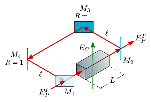
We consider a cavity illustrated in Fig. 1, in which there is a nonlinear medium of length in one arm, driven by a field that travels the medium in one direction only [23, 38]. We assume that the input and output mirrors, and , have identical reflectance and transmittance amplitudes (with ), whereas the other two mirrors are fully reflecting (). We also assume that the mirror separation is adjusted so that the cavity is tuned to near resonance with the applied fields. The nonlinear medium consists of a three-level atomic system with energy levels () and in a -type configuration (), interacting with probe and coupling lasers of frequencies and , with amplitudes and , respectively (see Fig. 2). The probe laser acts on the dipole-allowed transition , with energy difference and frequency detuning . The coupling laser couples to the other dipole-allowed transition , with energy difference and frequency detuning .
In the semiclassical approximation, where the system interacts with the classical electromagnetic fields of the two lasers, the Liouville equations of the density-matrix elements in the dipole and rotating wave approximation, including NDD interaction as described in [37], have the form
| (1a) | ||||
| (1b) | ||||
| (1c) | ||||
| (1d) | ||||
| (1e) | ||||
where and are complex, microscopic, slowly-varying electric field envelopes of the probe and coupling fields, respectively; and are the radiative decay rates from level to levels and , respectively; population decays from level back to level at a rate in non-radiative manner, and we define ; is the Rabi frequency of the probe field and () the Rabi frequency of the coupling field; is the dipole matrix element for transition and for transition (). Equations (1) describe the atomic dynamics of the system. is the dipole-dipole induced decay rate due to NDD interaction to level and to level [37].
The combined electric field acting on each atom inside the cavity is the sum of the probe and coupling fields, so that
| (2) |
The probe field at frequency (interacting with the atomic transition ) circulates inside the cavity acting as the cavity field. The coupling field at frequency (coupling transition ) does not circulate inside the optical ring cavity as shown in Fig. 1. However, the two fields propagate through the nonlinear medium in the same direction, so the first-order Doppler effect in this three-level, EIT system can be eliminated [16]. In fact, the coupling field behaves like a controlling field. The field enters the cavity from the partially transparent mirror and drives the nonlinear medium. To determine the field inside the unidirectional ring cavity, we write the relations obtained by boundary conditions [38]
| (3) | ||||
| (4) |
where the length of the atomic sample is specified by the parameter , is the side arm length between and (and also and ), and the time taken by light to travel from mirror to via mirrors and is given by . The cavity frequency detuning is defined as , where is the frequency of the nearest cavity mode to frequency , and represents the round-trip length of the ring cavity.
The dynamical evolution of the probe field inside the optical cavity is described by the Maxwell’s equation (in the slowly-varying envelope approximation) [38]
| (5) |
where is the induced atomic polarization responsible for AOB, and is the number density of atoms. In order to obtain the polarization , one needs to first solve the set of density-matrix equations (1) in the steady-state limit, then integrate (5) over the length of the atomic sample using (3) and (4). The steady-state boundary conditions can be written as [38]
| (6) | ||||
| (7) |
3 Results and Discussion
We solved equations (1) numerically and plotted the cavity output field () versus the cavity input field () for various parametric values of the coupling field and NDD interaction parameter. The output-input features for a system showing OB are shown in Figs. 3–6.
Figure 3(a) shows the curves for a three-level system in Raman configuration of its levels with no dipole-dipole interaction for different values of the coupling field. The atomic sample is kept inside the cavity (see Fig. 1). The parameters used were , , , and as the cooperative parameter for OB [38]. We changed to , , , , and . For a small , the OB threshold was large (solid line curve). When we increased , the threshold reduced, as seen in the figure. For a very large , the OB feature disappeared. The effect of a finite detuning of the coupling field is shown in Fig. 3(b). Here, the only parameter modified was leaving the other parameters unchanged. The non-zero coupling field detuning enhanced the OB threshold, as it can be observed by comparing the solid lines in Figs. 3(a) and 3(b). This threshold decreased for bigger values of the coupling field. The different curves correspond to values of , , , , and (see [38]).
Figures 4(a,b) showed the impact of non-zero, real and imaginary parts of NDD interaction. We used parameters , , , and . The effect of the imaginary part of NDD interaction is depicted in the curves plotted (Fig. 4(a)) for , , , , and . For smaller values of (, ), the curves showed OB. For a further increase in the value of (, , ), we observed the interesting phenomenon of optical multistabilty in the curves. The threshold of all these OB and multistability curves can be altered by modifying the value of the coupling field because this changes the induced coherence and hence the threshold. One such interesting study is shown in Fig. 4(b), where we changed to but kept all other parameters the same. By doing so, the threshold of OB and multistability curves came down. Again, this was due to the altered induced coherence.
In Fig. 5(a,b), we showed the controllability of OB by keeping the values of an NDD interaction parameter fixed. Parameters used for Fig. 5(a) were , , , and . We plotted curves for , , , and . At lower values of (1.0 and 3.0), we found multistability that gradually changed to OB as further increased to 5.0, 7.0 and 10.0. Thus for a fixed value of the NDD parameter (imaginary part), the transition from OB to multistability can be controlled by changing the coupling field strength. However, when we introduced the real part of a NDD parameter, such as in Fig. 5(b), the shape of all curves remained similar to those in Fig. 5(a) but the OB threshold of all curves increased. This effect is because of the associated increase in the system’s dampening that reduces the induced coherence.
For Fig. 6(a), the values for the NDD parameters were , , while for Fig. 6(b), the values were , and . Figures 6(a,b) showed reduction in the multistability structure for when compared with Fig. 5(a,b). still showed multistability, but the threshold raised as compared to those in Figs. 5(a,b). For further increase in , all curves displayed OB but with an augmented threshold value. The physical interpretation of these results is implicit in the manipulation of the physical properties of the three-level, EIT medium considered in this work. We achieved this by varying the coupling field and the NDD interaction parameters in the atomic system that changed its generated atomic coherence [37]. While keeping the coupling field constant, we varied the NDD parameters to control absorption, dispersion, and nonlinearity of the medium and to get changes in its OB.
4 Conclusion
In this work, we studied the optical bistability displayed by a three-level, -type electromagnetic induced transparency medium including near dipole-dipole interaction. The inclusion of NDD interaction provided another control parameter for changing the absorption, dispersion, and nonlinearity of such EIT system. In fact, by modifying the number density of the atomic medium, we may obtain wanted values of NDD parameters. Consequently, by the combined effect of the coupling field and NDD interaction parameters, the system exhibits interesting changes as it passes from OB to optical multistability. This results could be experimentally realized in the three-level atomic system described in Refs. [23, 38].
Acknowledgments
One of us (A.J.) is thankful to G. Duree (RHIT) for his interest and support for this work.
References
- Mandel and Wolf [1995] L. Mandel, E. Wolf, Optical coherence and quantum optics, Cambridge University Press, New York, 1995.
- Lugiato [1984] L. A. Lugiato, Theory of optical bistability, in: E. Wolf (Ed.), Progress in Optics, volume 21, North Holland, Amsterdam, 1984, pp. 69–216.
- Gibbs [1985] H. M. Gibbs, Optical Bistability: Controlling Light with Light, Academic Press, Orlando, 1985.
- Gibbs et al. [1976] H. M. Gibbs, S. L. McCall, T. N. C. Venkatesan, Differential gain and bistability using a sodium-filled fabry-perot interferometer, Phys. Rev. Lett. 36 (1976) 1135–1138. doi:10.1103/PhysRevLett.36.1135.
- Venkatesan and McCall [1977] T. N. C. Venkatesan, S. L. McCall, Optical bistability and differential gain between 85 and 296k in a fabry‐perot containing ruby, App. Phys. Lett. 30 (1977) 282–284. doi:10.1063/1.89368.
- Agrawal and Carmichael [1979] G. P. Agrawal, H. J. Carmichael, Optical bistability through nonlinear dispersion and absorption, Phys. Rev. A 19 (1979) 2074–2086. doi:10.1103/PhysRevA.19.2074.
- Boyd [2008] R. B. Boyd, Nonlinear Optics, 3rd ed., Academic Press, Boston, 2008.
- Lugiato et al. [1980] L. A. Lugiato, J. D. Farina, L. M. Narducci, Quantum-statistical treatment of the transient in absorptive optical bistability—local relaxation, Phys. Rev. A 22 (1980) 253–260. doi:10.1103/PhysRevA.22.253.
- Lugiato et al. [1981] L. A. Lugiato, V. Benza, L. M. Narducci, J. D. Farina, Optical bistability, instabilities and higher order bifurcations, Opt. Commun. 39 (1981) 405–410. doi:https://doi.org/10.1016/0030-4018(81)90233-9.
- Arimondo [1996] E. Arimondo, Coherent population trapping in laser spectroscopy, in: E. Wolf (Ed.), Progress in Optics, volume 35, North Holland, Amsterdam, 1996, pp. 257–354.
- Harris [1997] S. E. Harris, Electromagnetically induced transparency, Phys. Today 50 (1997) 36–42. doi:10.1063/1.881806.
- Marangos [1998] J. P. Marangos, Electromagnetically induced transparency, Journal of Modern Optics 45 (1998) 471–503. doi:10.1080/09500349808231909.
- Boller et al. [1991] K. J. Boller, A. Imamoğlu, S. E. Harris, Observation of electromagnetically induced transparency, Phys. Rev. Lett. 66 (1991) 2593–2596. doi:10.1103/PhysRevLett.66.2593.
- Field et al. [1991] J. E. Field, K. H. Hahn, S. E. Harris, Observation of electromagnetically induced transparency in collisionally broadened lead vapor, Phys. Rev. Lett. 67 (1991) 3062–3065. doi:10.1103/PhysRevLett.67.3062.
- Li and Xiao [1995] Y.-q. Li, M. Xiao, Electromagnetically induced transparency in a three-level -type system in rubidium atoms, Phys. Rev. A 51 (1995) R2703–R2706. doi:10.1103/PhysRevA.51.R2703.
- Gea-Banacloche et al. [1995] J. Gea-Banacloche, Y.-q. Li, S.-z. Jin, M. Xiao, Electromagnetically induced transparency in ladder-type inhomogeneously broadened media: Theory and experiment, Phys. Rev. A 51 (1995) 576–584. doi:10.1103/PhysRevA.51.576.
- Xiao et al. [1995] M. Xiao, Y.-q. Li, S.-z. Jin, J. Gea-Banacloche, Measurement of dispersive properties of electromagnetically induced transparency in rubidium atoms, Phys. Rev. Lett. 74 (1995) 666–669. doi:10.1103/PhysRevLett.74.666.
- Wang et al. [2001] H. Wang, D. Goorskey, M. Xiao, Enhanced Kerr nonlinearity via atomic coherence in a three-level atomic system, Phys. Rev. Lett. 87 (2001) 073601. doi:10.1103/PhysRevLett.87.073601.
- Yang et al. [2004] W. Yang, A. Joshi, M. Xiao, Controlling dynamic instability of three-level atoms inside an optical ring cavity, Phys. Rev. A 70 (2004) 033807. doi:10.1103/PhysRevA.70.033807.
- Yang et al. [2005] W. Yang, A. Joshi, M. Xiao, Chaos in an electromagnetically induced transparent medium inside an optical cavity, Phys. Rev. Lett. 95 (2005) 093902. doi:10.1103/PhysRevLett.95.093902.
- Joshi and Xiao [2006] A. Joshi, M. Xiao, Stochastic resonance in atomic optical bistability, Phys. Rev. A 74 (2006) 013817. doi:10.1103/PhysRevA.74.013817.
- Joshi and Xiao [2008] A. Joshi, M. Xiao, Noise-induced switching via fluctuating atomic coherence in an optical three-level bistable system, J. Opt. Soc. Am. B 25 (2008) 2015–2020. doi:10.1364/JOSAB.25.002015.
- Joshi and Xiao [2006] A. Joshi, M. Xiao, Controlling nonlinear optical processes in multi-level atomic systems, in: E. Wolf (Ed.), Progress in Optics, volume 49, North Holland, Amsterdam, 2006, pp. 97–175.
- Bowden [1993] C. M. Bowden, Near dipole-dipole interaction effects in quantum and nonlinear optics, in: I. Ramarao (Ed.), Recent Developments in Quantum Optics, Plenum Press, New York, 1993, pp. 55–63.
- Bowden et al. [1991] C. M. Bowden, A. Postan, R. Inguva, Invariant pulse propagation and self-phase modulation in dense media, J. Opt. Soc. Am. B 8 (1991) 1081–1084. doi:10.1364/JOSAB.8.001081.
- Stroud et al. [1988] C. Stroud, C. Bowden, L. Allen, Self-induced transparency in self-chirped media, Opt. Commun. 67 (1988) 387–390. doi:https://doi.org/10.1016/0030-4018(88)90033-8.
- Inguva and Bowden [1990] R. Inguva, C. M. Bowden, Spatial and temporal evolution of the first-order phase transition in intrinsic optical bistability, Phys. Rev. A 41 (1990) 1670–1676. doi:10.1103/PhysRevA.41.1670.
- Ben-Aryeh et al. [1987] Y. Ben-Aryeh, C. Bowden, J. Englund, Longitudinal spacial first-order phase transition in a system of coherently-driven, two-level atoms, Opt. Commun. 61 (1987) 147–150. doi:https://doi.org/10.1016/0030-4018(87)90237-9.
- Yang and John [2007] S. Yang, S. John, Exciton dressing and capture by a photonic band edge, Phys. Rev. B 75 (2007) 235332. doi:10.1103/PhysRevB.75.235332.
- Brennen et al. [2000] G. K. Brennen, I. H. Deutsch, P. S. Jessen, Entangling dipole-dipole interactions for quantum logic with neutral atoms, Phys. Rev. A 61 (2000) 062309. doi:10.1103/PhysRevA.61.062309.
- El-Ganainy and John [2013] R. El-Ganainy, S. John, Resonant dipole–dipole interaction in confined and strong-coupling dielectric geometries, New J. Phys. 15 (2013) 083033. doi:doi.org/10.1088/1367-2630/15/8/083033.
- Mohseni et al. [2008] M. Mohseni, P. Rebentrost, S. Lloyd, A. Aspuru-Guzik, Environment-assisted quantum walks in photosynthetic energy transfer, The Journal of Chemical Physics 129 (2008) 174106. doi:10.1063/1.3002335.
- Kobayashi et al. [1995] T. Kobayashi, Q. Zheng, T. Sekiguchi, Resonant dipole-dipole interaction in a cavity, Phys. Rev. A 52 (1995) 2835–2846. doi:10.1103/PhysRevA.52.2835.
- Agarwal and Gupta [1998] G. S. Agarwal, S. D. Gupta, Microcavity-induced modification of the dipole-dipole interaction, Phys. Rev. A 57 (1998) 667–670. doi:10.1103/PhysRevA.57.667.
- Hopmeier et al. [1999] M. Hopmeier, W. Guss, M. Deussen, E. O. Göbel, R. F. Mahrt, Enhanced dipole-dipole interaction in a polymer microcavity, Phys. Rev. Lett. 82 (1999) 4118–4121. doi:10.1103/PhysRevLett.82.4118.
- Levene et al. [2003] M. J. Levene, J. Korlach, S. W. Turner, M. Foquet, H. G. Craighead, W. W. Webb, Zero-mode waveguides for single-molecule analysis at high concentrations, Science 299 (2003) 682–686. doi:10.1126/science.1079700.
- Joshi and Serna [2019] A. Joshi, J. D. Serna, Absorption–dispersion in a three-level electromagnetically induced transparency medium including near dipole–dipole interaction effects, Opt. Commun. 430 (2019) 119–130. doi:doi.org/10.1016/j.optcom.2018.08.018.
- Joshi and Xiao [2010] A. Joshi, M. Xiao, Atomic optical bistability in two- and three-level systems: perspectives and prospects, J. Mod. Opt. 57 (2010) 1196–1220. doi:10.1080/09500340.2010.492919.
Figure Captions
Figure 1: Schematic diagram of a unidirectional ring cavity having four
mirrors () and an atomic vapor cell of length . Mirrors
and are perfectly reflecting mirrors (). The incident and
transmitted fields are represented by and , respectively,
while the coupling field is represented by .
Figure 2: Schematic diagram of the three-level system in a
-configuration driven by probe and coupling lasers of frequencies
and , respectively.
Figure 3: Optical bistability (in terms of output vs. input cavity field)
for a three-level system in Raman configuration of its states. The Rabi
frequency is variable. (a) , (b) .
Figure 4: Output vs. input cavity field of the system as a result of
non-zero, near dipole-dipole interaction (NDD). NDD (imaginary part) parameter
, which is varying. (a) , (b) .
Figure 5: Output vs. input cavity field of the system for non-zero, near
dipole-dipole interaction with . The Rabi frequency
is variable. NDD (real part) parameters and
are changed as: (a) ,
(b) .
Figure 6: Same as Fig. 5, with .
(a) , (b) .