Blip glitches in Advanced LIGO data
Abstract
Blip glitches are short noise transients present in data from ground-based gravitational-wave observatories. These glitches resemble the gravitational-wave signature of massive binary black hole mergers. Hence, the sensitivity of transient gravitational-wave searches to such high-mass systems and other potential short duration sources is degraded by the presence of blip glitches. The origin and rate of occurrence of this type of glitch have been largely unknown. In this paper we explore the population of blip glitches in Advanced LIGO during its first and second observing runs. On average, we find that Advanced LIGO data contains approximately two blip glitches per hour of data. We identify four subsets of blip glitches correlated with detector auxiliary or environmental sensor channels, however the physical causes of the majority of blips remain unclear.
1 Introduction
The Laser Interferometer Gravitational-wave Observatories (LIGO) [1] and the Virgo observatory [2] have successfully identified several mergers of compact binaries in their second generation (Advanced) configuration. The first observing run of Advanced LIGO (O1) took place from September 12th 2015 to January 19th 2016, concluding with the observation of three binary black hole coalescences [3, 4, 5]. The second observing run (O2) started in November 30th 2016 and lasted until August 25th 2017, with Advanced Virgo joining the second generation network in August 2017. The O2 run brought the first gravitational wave of a coalescing neutron star [6], as well as several other black-hole mergers [7, 8, 9, 10].
The sensitivity of interferometric gravitational-wave detectors to astrophysical signals may be assessed via the power spectral density (PSD) of a stationary Gaussian process describing noise contributions to the measured strain [11]. This description is commonly used in assessing the long-term evolution of detector performance. However, it neglects the presence of transient (short duration) non-Gaussian features in the detector noise [12, 13], known as ‘glitches’. The presence of noise transients can substantially degrade the sensitivity of searches for transient gravitational-wave signals in the strain data [14]. Thus, it is of interest to describe, understand and, if possible, mitigate glitches.
A particular type of short duration noise transient commonly known as ‘blip glitch’ [13, 14, 10] is amongst the worst contributors to the background of transient gravitational-wave searches. Determining the source of blip glitches is crucial to improve the sensitivity of these searches. However, there are many different types of noise transients in the data and computer algorithms cannot easily distinguish blip glitches from other short-impulse noise transients. Here, we develop a method to identify blip glitches in gravitational-wave data and study possible sources of these noise transients in the Advanced LIGO detectors.
This manuscript is organised as follows. Sections 2 provides an overview on the Advanced LIGO detectors. Section 3 describes the morphology and characteristics of a blip glitch. In Sec. 4 we develop a method to identify times of blip glitches using PyCBC tools [15, 16, 17]. In Sec. 5 we investigate the origin of these blip glitches identified with PyCBC. Finally, the manuscript is summarised in Sec. 6.
2 The Advanced LIGO detectors
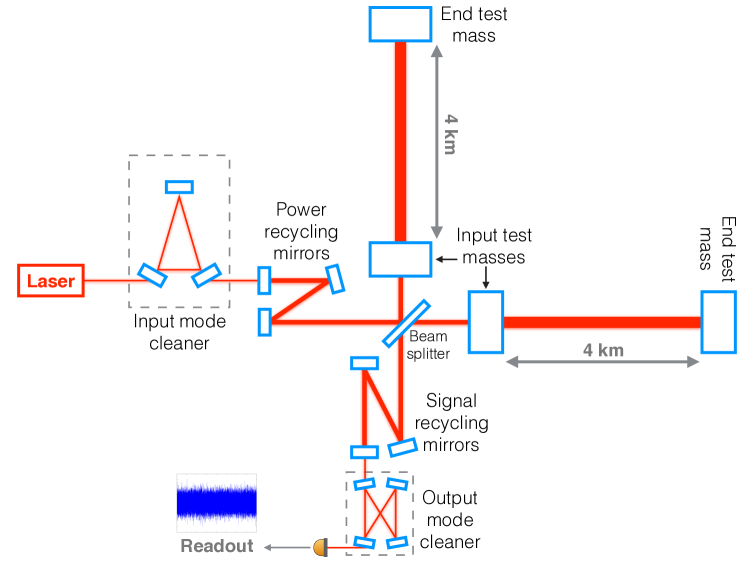
The basic design of the Advanced LIGO gravitational-wave detectors [1, 19] is a Michelson interferometer with Fabry-Pérot resonant cavities in each of the 4-km long arms. The resonance condition of the optical cavities is maintained by multiple servo-control loops. A simplified sketch of the optical configuration of an Advanced LIGO interferometer is shown in Fig. 1. The input mode cleaner stabilises the laser frequency and suppresses higher order spatial modes before the light enters the interferometer [20]. Between the input mode cleaner and the beam splitter, the power recycling mirror is placed to increase the effective laser power. The input and end test masses of the Fabry-Pérot arm cavities are suspended by a quadruple pendulum system [21, 22] and serve as test masses. The quadruple suspensions are mounted to actively stabilised in-vacuum optical tables that provide seismic isolation from the environment [23]. At the anti-symmetric output of the Michelson, the signal recycling mirror is used to maintain a broad frequency response of the detector. Finally, the output mode cleaner [24] filters out higher order spatial modes produced in the interferometer before the light enters the readout photodiodes. The signal measured by the photodetectors is digitised and calibrated to convert laser light power to relative mirror displacement [25, 26, 27]. This calibrated strain signal, , is the data analysed in the searches for gravitational waves.
The detector’s strain sensitivity to astrophysical signals is mainly limited by fundamental noise sources [1]. Thermal noise, stronger at lower frequencies, arises from the test masses and their suspension systems. Quantum noise includes shot noise at high frequencies and radiation pressure at low frequencies. Seismic noise is the main limiting factor at low frequencies. Technical noise sources, which are controllable by design, further shape the detector’s sensitivity. Several major upgrades were implemented between the Initial and Advanced LIGO generations to reduce these noise sources and improve the detectors’ sensitivities. For instance, the signal recycling cavity and the new quadruple pendulum suspension mentioned above were first introduced in the Advanced LIGO era. Moreover, larger and heavier test masses were built to reduce thermal noise and motion induced by quantum radiation pressure. During the first observing run of Advanced LIGO, the detectors’ strain noise was already between 4 and 30 times lower than in the final science run of Initial LIGO [19], depending on the frequency band. Further improvements will be implemented in the coming years until Advanced LIGO’s design sensitivity is reached, such as the gradual increase of the laser power and the injection of squeezed light to reduce quantum noise [1, 19, 28].
Technical, or hardware, and environmental noise sources can produce glitches visible in the calibrated strain data that limit the search’s sensitivity. Identifying the source of a particular glitch in a gravitational-wave detector is very challenging: in addition to the main gravitational-wave channel, there are over 200,000 auxiliary channels in each detector. These channels monitor the environmental conditions around the detector and the hardware behaviour of the interferometer [29]. Should a source for a certain type of glitch be identified, the detector issue may be fixed at the source to mitigate such glitches [30, 31, 32]. Alternatively, albeit less effectively, auxiliary channels can be used to identify times of occurrences and discard – referred to as a veto – the glitches from the data used in gravitational-wave searches [13, 14, 33]. Unfortunately, blip glitches are still of unknown origin and cannot be mitigated or safely vetoed.
3 Description of a blip glitch
A noise transient is categorised as a blip glitch if it is a very short duration transient, ms, with a large frequency bandwidth, Hz. Blip glitches are found in both LIGO detectors, located in Hanford (Washington state) and Livingston (Louisiana). There is also evidence for the presence of similar short noise transients in the Virgo (Italy) and GEO 600 (Germany) gravitational-wave observatories. We focus here on blip glitches observed in Advanced LIGO data.
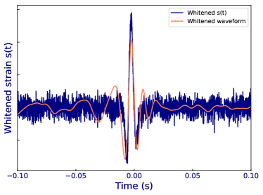
The characteristic time-domain shape of a blip glitch resembles the gravitational-wave imprint of compact binaries with large total mass, highly asymmetric component masses and spins anti-aligned with the orbital angular momentum (see Fig. 2). While occurrences of blip glitches are independent between the two LIGO interferometers, blip glitches contribute to the background of transient gravitational-wave searches. This is because there is a nonzero probability of random (accidental) coincidences in time between blip glitches in different detectors, or between blips and random noise; this probability is estimated by performing analyses with unphysical time-shifts between detectors [17]. Hence, the presence of blip glitches degrades the search sensitivity to high-mass systems.
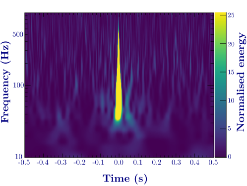
A time-frequency representation [34, 35] of a typical blip glitch is shown in Fig. 3. This glitch morphology in the calibrated gravitational-wave channel was first observed in Initial LIGO, and has persisted on into the Advanced LIGO generation. The absence of methods to easily identify blip glitches in Initial LIGO made it difficult to obtain meaningful statistics on the rate of such noise transients. Furthermore, the few blips observed did not show significant correlations with any auxiliary channels that could reveal the source of the noise.
Two main effects complicate source identification and mitigation of blip glitches. First, many different physical mechanisms could be responsible for these short impulses, and sensors may not witness these processes or record them at high enough bandwidth. Second, the servo-control loops of the interferometer make it difficult to identify the original sources because loop actuators may compensate for the effect of the original transient, propagating the impact into the main calibrated gravitational-wave channel. In the following sections, we develop a method based on gravitational-wave searches to identify blip glitches in Advanced LIGO data and study the origin of these noise transients.
4 Identifying blip glitches in LIGO data
Blip glitches always trigger the same region of parameter space in the PyCBC search [16, 17, 15] for gravitational waves from compact binary coalescences. Investigation of the loudest single-detector background events revealed that this region corresponds to short waveforms with total masses greater than [36, 14]. While these waveform templates are potential blip-glitch finders, gravitational-wave searches use various ranking statistics to separate noise transients from astrophysical events. Particularly, the PyCBC search uses a high frequency sine-Gaussian discriminator [36] to reject a type of blip glitch that contains excess power at higher frequencies than expected for the waveform templates. Hence, the results from a gravitational-wave search are not optimal to find the maximum possible number of blip glitches. We can, however, create a blip-glitch search using a subset of short waveform templates and PyCBC matched-filtering techniques. In the O1 data set, we used a reduced template bank containing 14 templates, instead of the 250,000 used for gravitational-wave searches [37]. The PyCBC template bank for O2 was increased in parameter space by approximately 60 [38], so the reduced template bank for the blip search was increased to 30 templates. Furthermore, with the development of PyCBC Live [39], the O2 blip-glitch search was performed in low latency to rapidly diagnose variations in the rate of blip glitches.
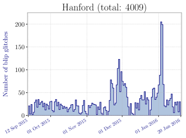
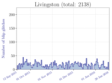
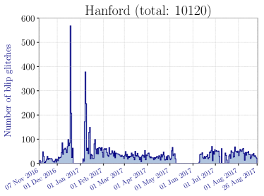
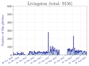
To optimise the blip-glitch search, we define two signal-to-noise ratio (SNR) thresholds. A lower SNR threshold of is used to avoid random fluctuations of Gaussian data. An upper SNR threshold of is used to avoid loud noise events that are clearly not blips but contain similar morphology near loud, long-duration noise transients. Each single blip glitch can produce multiple search triggers, so we cluster triggers in 0.1 s time windows after the single detector matched filtering to identify individual glitches. Finally, glitches that do not match our definition of a blip glitch are manually removed (for instance, short noise transients with a small frequency bandwidth, such as small 60 Hz power glitches). The resulting number of blip glitches per calendar day found in each LIGO detector is shown in Fig. 4, with the O1 data set in the top row and the O2 data set in the bottom row.
An alternative approach to identify blip glitches, not available during the development of the methods used here, is a new citizen science effort called Gravity Spy [40]. This project combines crowdsourcing with machine learning to categorise different types of glitches found in LIGO data. The glitches classified as blips in this manuscript encompass four different categories in the Gravity Spy classification: blips, repeated blips, tomtes and koi fish. Further investigations on the different types of glitches from Gravity Spy are beyond the scope of this paper. Here, we restrict ourselves to the blip glitches obtained with PyCBC.
The rate of blip glitches in each LIGO detector is given by the ratio of the number of blips to the duration of analysed data (analysed time), which is different than the calendar time used in Fig. 4. In the O1 run, the median blip-glitch rate in the Hanford observatory (LHO) was slightly higher than in the Livingston observatory (LLO), with approximately 39 blips per day of LHO analysed time versus 31 blips per day of LLO analysed time. In the O2 run, the median blip-glitch rate increased in both detectors: approximately 47 blips per day of LHO analysed time and 48 blips per day of LLO analysed time. The rate increase was more significant in the Livingston observatory, and both detectors had comparable rates.
To show that blip glitches are not correlated in time between detectors, we perform a simple test to determine if the number of blips occurring within a small time difference between detectors is what would be expected from random coincidences. Assuming that blip glitches are uncorrelated between both detectors, the expected number of coincidences within a particular time window is
| (1) |
with the maximum time difference allowed between detectors, the duration of coincident data (given by times during which both LIGO detectors were collecting data suitable for analysis), and and the number of blip glitches occurring during coincident data for Hanford and Livingston, respectively. Table 1 shows the expected coincidences for different time windows, as well as the found coincidences in the O1 and O2 data sets. For an astrophysical signal, the maximum arrival time difference between the two LIGO detectors is ms. In the PyCBC search for gravitational waves, this time difference is allowed to be ms to account for timing uncertainties. As can be seen in Table 1, there are no coincidences found within this time window. Coincidences found in larger time windows are consistent with the expected values.
| Maximum time difference (s) | 0.015 | 0.1 | 1 | 10 |
|---|---|---|---|---|
| O1 Expected | 0.03 | 0.20 | 1.97 | 19.70 |
| O1 Found coincidences | 0 | 0 | 2 | 24 |
| O2 Expected | 0.13 | 0.84 | 8.38 | 83.76 |
| O2 Found coincidences | 0 | 1 | 4 | 65 |
5 Investigating the origin of blip glitches
The fact that blips are not correlated in time between different detectors indicates that they are likely of instrumental or environmental origin rather than of astrophysical origin. The cosmic ray detector located at the Hanford site has shown that there is no unusual cosmic-ray activity at times of blip glitches [41], and for a long time no correlations with other environmental sensors have been detected. The blip glitches found with PyCBC tools provide, for the first time, meaningful statistics to investigate the source of blip glitches and explore correlations between the rate of blip glitches and the status of the detectors. In this section we briefly explain conclusions derived from investigating sources of blip glitches in the Advanced LIGO detectors. As we will see, these investigations indicate that there is not one single source for all blip glitches. Instead, we find that there are different subsets of blips. This is not surprising, since the simple morphology of such short impulses could be produced by many possible mechanisms without any noticeable distinction.
The LIGO detectors have radio-frequency control systems with some parts including analog components that interferometrically determine and control the length and alignment of the resonant optical cavities. Some of those control systems’ error and control signals are stored digitally, but none are sampled at a rate higher than 16384 Hz, and thus information about their signal content above 8 kHz is not recorded. Similarly, the observatories also contain many slow servo systems and monitor signals which are only recorded at a rate much slower than the detector bandwidth, i.e. 16 Hz. These systems, however, may influence and have a coupling mechanism to the detector’s primary signal at higher frequencies. This study has been performed using digitally stored auxiliary channels, which might not be effective witnesses of blip glitches and their full signal content. Thus, even when finding hints to the origin of a subset of blip glitches, we may not be able to fully characterise and reveal mechanisms causing these noise transients.
As a first step, we systematically looked for correlations between blip glitches and auxiliary channels using the Hierarchical Veto (HVeto) pipeline [42]. This algorithm is designed to find time correlations between transients in the main calibrated gravitational-wave channel and in auxiliary channels with negligible sensitivity to gravitational waves (known as “safe” channels). The HVeto pipeline runs daily on all glitches for detector characterisation purposes. However, running on longer periods of data becomes computationally challenging given the large amount of triggers produced during an observing run. With the lists of blip glitches, which constitute only a fraction of the totality of the triggers, we can drastically reduce the amount of data to analyse and run HVeto on longer data segments. We found two subsets of blip glitches that showed correlations with auxiliary channels, one which had already been identified during the course of the run (described in Sec. 5.2) and one new subset (described in Sec. 5.4). However, the majority of blip glitches did not show correlations with the safe, fast-recording channels used in HVeto. Additional investigations revealed two more subsets of blip glitches, described in Secs. 5.1 and 5.3.
5.1 Correlation with humidity
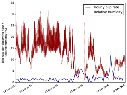
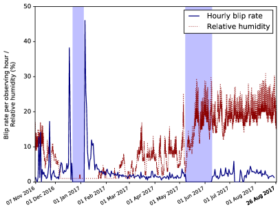
At the end of O1, a strong correlation between the rate of blip glitches and the outside temperature was found at the LIGO Hanford detector [43]. The outside temperature is well correlated with the inside relative humidity: during the winter, heating is required to maintain an appropriate constant inside temperature and the inside relative humidity decreases. As can be seen in Fig. 5, there was a significant increase in the rate of blip glitches during periods when the measured relative humidity inside the building dropped below at the Hanford site. Extended periods of low relative humidity in the winter also showed an increase in the rate of blip glitches in O2, as shown in Fig. 5.
The exact cause of this correlation is still not clear. Dry conditions might favour the build up and discharge of static electricity on electronic cooling fans. Alternatively, there may be current leakage paths that discharge in bursts when the pathways are dry. Therefore, it might be possible that these blip glitches are due to electronic discharges, which could be mitigated or reduced by maintaining the inside relative humidity above critical levels.
5.2 Correlation with laser intensity stabilisation
During the first half of O2, we found that a subset of blip glitches at Hanford originated from the Pre-Stabilised Laser (PSL). A louder blip glitch with similar morphology was recorded at a PSL auxiliary channel at the same time as these blip glitches, indicating a strong correlation between the PSL and the blip in the main calibrated gravitational-wave channel. The auxiliary channel in question witnesses one of the photodiodes at the inner loop of the Intensity Stabilisation Servo (ISS). This ISS is a feedback control system designed to stabilise the power of the PSL. We briefly summarise below the parts of the PSL and the ISS that are relevant for this section; a complete description of these systems can be found in [44, 45].
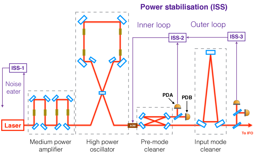
A simplified sketch of the optical configuration of the PSL, including all stages of the ISS, is shown in Fig. 6. The ISS consists of three loops: the noise eater, the inner loop, and the outer loop. The noise eater is placed directly at the laser output to reduce the relaxation oscillation of the laser. The inner and outer loops are situated after the Pre-Mode Cleaner (PMC) to stabilise the power in the detection frequency band (10 Hz to 10 kHz). The PMC, which improves the quality and pointing stability of the laser beam, passively suppresses power fluctuations at radio frequencies only. Power fluctuations at lower frequencies are measured downstream of the PMC by one pick-off port of the PMC (the photodiode labelled PDA in Fig. 6). Through an analog electronics feedback control loop and an acousto-optic modulator (AOM) as actuator, the inner loop stabilises these lower-frequency fluctuations. The outer loop is responsible for the ultimate power stability in the interferometer. This loop, implemented to achieve the required power stability at 10 Hz, senses the light from a photodetector directly upstream of the interferometer. Furthermore, the outer loop improves the power stability of the inner loop and compensates for power noise that is not suppressed in the previous stages.
The PSL blip glitches occurred from the beginning of the O2 run (November 2016) until the end of February 2017. A total of 25 blip glitches correlated to the ISS were found in that period, approximately 0.25% of the population of blip glitches reported in Sec. 4 for the entire O2 data set of the LIGO Hanford observatory. The correlation with the auxiliary channel recording the signal from the PDA allowed to identify instances of PSL blip glitches using Omicron111 Omicron [46] is an algorithm used to identify excess power in gravitational-wave data via a constant- time-frequency wavelet transform [35]. This algorithm is used to find noise transients in the gravitational-wave channel and in the auxiliary channels.. These glitches were then vetoed in the gravitational-wave searches. The exact cause of the laser glitching remains unknown.
5.3 Correlation with computer errors
The Advanced LIGO detectors have a complex data transfer and acquisition architecture. Many subsystems and channels require real-time digital controls, and real-time analog data acquisition for analysis and archiving [1]. Data acquisition and control applications for the various subsystems are defined and built using the Real-Time Code Generator (RCG) [47]. The RCG control systems describe the desired execution sequence for different code infrastructures.
Interferometer sensor and actuator signals flow between Analog-to-Digital and Digital-to-Analog Converters (ADC and DAC) through a customised computer infrastructure, located in rooms separate from the interferometer instrumentation. The global control system is necessarily distributed between the corner station and end-station buildings housing the detectors. Thus, the computers that sense and control the interferometer are in several, often distant, physical locations. They are digitally connected via commercial, computer-to-computer, high-speed network hardware and optical fibre. This Inter-Process Communication (IPC), both between individual cores of computers and between computers, could have errors that cause blip glitches.
The suspension (SUS) system is the actuator of the global length and angular control system, and thus the primary control loop controlling the differential arm lengths. Between O1 and O2, SUS control systems became too complicated for the standard real-time (front end) computers. Faster computers were installed at both LIGO sites to speed up both the SUS and the I/O Processor (IOP) control systems. The IOP is in charge of interfacing with the I/O hardware modules, and of synchronising with the interferometer timing system [1]. During the course of O2, a subset of blip glitches was identified in coincidence with times of computer errors related to the IOP and SUS control systems. While there are several different types of computer errors, we restrict ourselves here to the errors that were observed in coincidence with blip glitches during O2.
Timing errors appear, for instance, when the time between code cycles is outside the assigned limits, or when the code execution time is greater than the allowed time. An ADC overrun error can originate from: (i) data not arriving on time from the ADC modules, or (ii) channel misidentification by the IOP control system, which reads the ADC signal at the beginning of each cycle and assigns it to the corresponding channel. The ADCs have channel identification, and can therefore re-synchronise themselves when the error is associated to the latter. In that case, the RCG discards the data from the corresponding corrupted cycle. However, if the ADC error is associated to a timing error, it can propagate through the IPC to downstream control systems. Finally, an IPC error can indicate a fault in receiving IPC data via any IPC mechanism [47]. Computer errors seem to happen more frequently in Hanford than in Livingston, even though the two systems are identical.
| Control system | Total errors | Isolated errors |
|---|---|---|
| (1) IOP-SUSE{X/Y} | 1778 | - |
| (2) SUS-ETM{X/Y} | 1313 | 8 |
| (3) SUS-TMS{X/Y} | 129 | 1 |
| (4) SUS-ETM{X/Y}PI | 889 | 7 |
| (5) IOP-SEIE{X/Y} | 1732 | 13 |
| (6) ALS-E{X/Y} | 1180 | 7 |
| (7) ISC-E{X/Y} | 1197 | 7 |
It is still uncertain how the computer errors are causing a glitch in the main calibrated strain channel. One possibility could be the corrupted signal from the SUS getting to the interferometer sensing control (ISC) system. However, there does not seem to be a clear correlation between the type of error at the times of blip glitches: we have observed timing as well as ADC and IPC errors. There are auxiliary channels for each control system that record occurrences of any type of computer errors. Here we look at seven systems between the corner station and both arm ends of the interferometer. In O2 data, the system with the largest number of computer errors is the IOP-SUS system, with 1778 errors on both end-X and end-Y (E{X/Y}) systems (832 and 946, respectively). From the blip glitches with SNR identified in Sec. 4, a total of 625 blips are in coincidence with IOP-SUS front-end computer errors. Computer errors also induce glitches louder than , which are not included in our lists of blip glitches. Hence, the percentage of IOP-SUS front-end computer errors associated with glitches in the main calibrated strain channel is currently unknown, and we can only estimate it to be larger than 35%.
Errors in the IOP-SUS system can propagate to downstream control systems. In Table 2 we indicate the number of errors found in the different systems, and how many of those errors did not propagate from the IOP-SUS system (isolated errors). Since there are some coincidences between the downstream systems, only 14 of the isolated errors are new with respect to the IOP-SUS system, 6 of which are in coincidence with a blip glitch. Hence, we find 631 blip glitches with SNR correlated with computer errors, approximately 6.2% of the population of blip glitches reported in Sec. 4 for the O2 data of the LIGO Hanford observatory.
5.4 Correlation with power recycling cavity control signals
Figure 7 shows the five primary resonant cavity systems in the Advanced LIGO detectors222There are different conventions in the literature describing the cavity basis. Some include a factor of two [48] while others do not [19].. The gravitational-wave channel is related to the reconstruction of differential length variation between the two arm cavities, (with and the length of the X arm and the Y arm, respectively). However, in order for the interferometer output to remain linearly proportional to , all five cavity systems must be controlled.
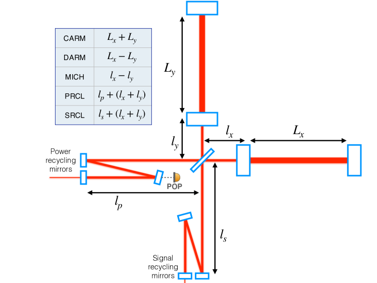
The cavities are controlled via an interferometric, Pound-Drever-Hall [49], radio-frequency (RF) demodulation scheme, described briefly as follows. Phase-modulated sidebands are intentionally instilled on the laser light input into the interferometer via electro-optic modulators. After resonating inside the interferometer’s optical cavities, this light is then captured on photodiodes positioned at various strategic pick-off ports. Thus, the pick-off port signal is a probe of the length (and alignment) of the cavity, serving as an error signal for the cavity length (or alignment) control system. The raw photodiode current signal is demodulated at the sideband frequencies and conditioned via a system of analog electronics. The resulting conditioned, demodulated signal is passed into either analog or digital control servos, depending on the necessary bandwidth for control. See further details of the control system in [48]. As a part of the out-of-loop diagnostics for this system, the raw light power levels on the photodiodes are also digitised and stored.
As mentioned at the beginning of Sec. 5, it is impractical to digitise all signals of this RF electronics system with high bandwidth. Therefore, this study can only use those signals that are stored to suggest correlations between the control system and the gravitational wave channel. In O2, we found that the diagnostic power level on one of these RF photodiodes – namely the Pick-Off port for the Power recycling cavity (POP) – showed loud blip glitches at the same time as a subset of blip glitches in the main calibrated channel, with comparable morphologies in both channels. This correlation has been seen in both LIGO detectors: 168 blips in O2 Hanford data and 199 blips in O2 Livingston data showed correlation with the POP diagnostic channel. That makes approximately 1.7% of the O2 population of blip glitches reported in Sec. 4 for the LHO data, and 2.2% of the O2 population for LLO data. Further investigations to understand the source of these glitches and possibly mitigate them are currently ongoing.
6 Conclusions
In this paper we described a type of noise transients in gravitational-wave data commonly known as blip glitches. During the first two observing runs of Advanced LIGO, thousands of blips were found in each LIGO detector using PyCBC techniques. Blip glitches significantly reduce the sensitivity of searches for high mass compact binaries. It is therefore important to identify the origin of these noise events so they can be mitigated from the searches. With the lists of blip glitches obtained, we conducted investigations on the origin of blip glitches and reported correlations with four different source channels: low relative humidity inside the building, laser intensity stabilisation, computer errors, and power recycling control signals.
Despite the importance of identifying sources of blip glitches, these were only four small subsets of all the blip glitches found. In total, less than 8% of LHO blip glitches and about 2% of LLO blip glitches in O2 data have shown a correlation with an auxiliary channel. Search pipelines are evolving to new ranking statistics that veto particular types of blip glitches from the searches (see for instance [36]). At the same time, investigations at the LIGO detectors continue during commissioning and observing runs. Now that gravitational waves from coalescing black holes represent an important astrophysical output of LIGO and Virgo, it becomes even more urgent to mitigate blip glitches from the data. Otherwise, we might not be able to distinguish between blip glitches and marginal gravitational-wave signals from high mass systems.
7 Acknowledgements
We would like to thank Jenne Driggers, Sheila Dwyer, Michael Landry and Jessica McIver for interesting discussions. We also thank the LIGO Lab and the whole team at the LIGO Hanford observatory for investigations performed at the site. MC acknowledges support from NSF grant PHY-1607449, the Simons Foundation, and the Canadian Institute For Advanced Research (CIFAR). TD acknowledges support from the Maria de Maeztu Unit of Excellence MDM-2016-0692. LKN received funding from the European Union Horizon 2020 research and innovation programme under the Marie Sklodowska-Curie grant agreement No 663830. This paper uses data from the Advanced LIGO detectors and computations have been performed on the LIGO Data Grid and on the Atlas computer cluster at the Albert Einstein Institute (Hannover).
References
References
- [1] The LIGO Scientific Collaboration. Advanced LIGO. Class Quant Grav. 2015;32(7):074001.
- [2] The Virgo Collaboration. Advanced Virgo: a second-generation interferometric gravitational wave detector. Class Quant Grav. 2015;32(2):024001. doi:10.1088/0264-9381/32/2/024001.
- [3] The LIGO Scientific Collaboration and the Virgo Collaboration. Observation of gravitational waves from a binary black hole merger. Phys Rev Lett. 2016;116(6):061102. doi:10.1103/PhysRevLett.116.061102.
- [4] The LIGO Scientific Collaboration and the Virgo Collaboration. GW151226: Observation of gravitational waves from a 22-solar-mass binary black hole coalescence. Phys Rev Lett. 2016;116(24):241103. doi:10.1103/PhysRevLett.116.241103.
- [5] The LIGO Scientific Collaboration and the Virgo Collaboration. Binary black hole mergers in the first Advanced LIGO observing run. Phys Rev X. 2016;6:041015. doi:10.1103/PhysRevX.6.041015.
- [6] The LIGO Scientific Collaboration, The Virgo Collaboration. GW170817: Observation of gravitational waves from a binary neutron star inspiral. Phys Rev Lett. 2017;119(16):161101.
- [7] The LIGO Scientific Collaboration and the Virgo Collaboration. GW170104: Observation of a 50-solar-mass binary black hole coalescence at redshift 0.2. Phys Rev Lett. 2017;118:221101. doi:10.1103/PhysRevLett.118.221101.
- [8] The LIGO Scientific Collaboration, The Virgo Collaboration. GW170608: Observation of a 19-solar-mass binary black hole coalescence. Astroph J Lett. 2017;851(2):L35.
- [9] The LIGO Scientific Collaboration, The Virgo Collaboration. GW170814: A three-detector observation of gravitational waves from a binary black hole coalescence. Phys Rev Lett. 2017;119(14):141101.
- [10] The LIGO Scientific Collaboration, The Virgo Collaboration. GWTC-1: A gravitational-wave transient catalog of compact binary mergers observed by LIGO and Virgo during the first and second observing runs. 2018;.
- [11] The LIGO Scientific Collaboration. Sensitivity of the Advanced LIGO detectors at the beginning of gravitational wave astronomy. Phys Rev. 2016;D93(11):112004. doi:10.1103/PhysRevD.93.112004, 10.1103/PhysRevD.97.059901.
- [12] Blackburn L, et al. The LSC Glitch Group: Monitoring Noise Transients during the fifth LIGO Science Run. Class Quant Grav. 2008;25:184004. doi:10.1088/0264-9381/25/18/184004.
- [13] The LIGO Scientific Collaboration, The Virgo Collaboration. Characterization of transient noise in Advanced LIGO relevant to gravitational wave signal GW150914. Class Quant Grav. 2016;33(13):134001.
- [14] The LIGO Scientific Collaboration, The Virgo Collaboration. Effects of data quality vetoes on a search for compact binary coalescences in Advanced LIGO’s first observing run. Class Quant Grav. 2018;35(6):065010.
- [15] Nitz AH, Harry IW, Biwer CM, Brown D, Willis J, Dal Canton T, et al.. PyCBC github repository;. https://github.com/ligo-cbc/pycbc/.
- [16] Dal Canton T, et al. Implementing a search for aligned-spin neutron star-black hole systems with advanced ground based gravitational wave detectors. Phys Rev D. 2014;90(8):082004. doi:10.1103/PhysRevD.90.082004.
- [17] Usman SA, Nitz AH, Harry IW, Biwer CM, Brown DA, Cabero M, et al. The PyCBC search for gravitational waves from compact binary coalescence. Class Quant Grav. 2016;33(21):215004.
- [18] Cabero Müller MA. Gravitational-wave astronomy with compact binary coalescences: from blip glitches to the black hole area increase law. Leibniz Universität Hannover; 2018. Available from: https://www.repo.uni-hannover.de/handle/123456789/3452.
- [19] The LIGO Scientific Collaboration, The Virgo Collaboration. GW150914: The Advanced LIGO detectors in the era of first discoveries. Phys Rev Lett. 2016;116:131103. doi:10.1103/PhysRevLett.116.131103.
- [20] Mueller CL, Arain MA, Ciani G, DeRosa RT, Effler A, Feldbaum D, et al. The Advanced LIGO input optics. Rev Scientific Instruments. 2016;87(1):014502. doi:10.1063/1.4936974.
- [21] Aston SM, et al. Update on quadruple suspension design for Advanced LIGO. Class Quant Grav. 2012;29(23):235004. doi:10.1088/0264-9381/29/23/235004.
- [22] Carbone L, et al. Sensors and Actuators for the Advanced LIGO Mirror Suspensions. Class Quant Grav. 2012;29:115005. doi:10.1088/0264-9381/29/11/115005.
- [23] Matichard F, et al. Seismic isolation of Advanced LIGO: Review of strategy, instrumentation and performance. Class Quant Grav. 2015;32(18):185003. doi:10.1088/0264-9381/32/18/185003.
- [24] Fricke TT, Smith-Lefebvre ND, Abbott R, Adhikari R, Dooley KL, Evans M, et al. DC readout experiment in Enhanced LIGO. Class Quant Grav. 2012;29(6):065005.
- [25] The LIGO Scientific Collaboration. Calibration of the Advanced LIGO detectors for the discovery of the binary black-hole merger GW150914. Phys Rev D. 2017;95:062003. doi:10.1103/PhysRevD.95.062003.
- [26] Viets A, et al. Reconstructing the calibrated strain signal in the Advanced LIGO detectors. Class Quant Grav. 2018;35(9):095015. doi:10.1088/1361-6382/aab658.
- [27] The Virgo Collaboration. Calibration of Advanced Virgo and Reconstruction of the Gravitational Wave Signal during the Observing Run O2. Class Quant Grav. 2018;35(20):205004. doi:10.1088/1361-6382/aadf1a.
- [28] Miller J, Barsotti L, Vitale S, Fritschel P, Evans M, Sigg D. Prospects for doubling the range of Advanced LIGO. Phys Rev. 2015;D91:062005. doi:10.1103/PhysRevD.91.062005.
- [29] Effler A, Schofield RMS, Frolov VV, González G, Kawabe K, Smith JR, et al. Environmental influences on the LIGO gravitational wave detectors during the 6th science run. Class Quant Grav. 2015;32(3):035017.
- [30] Nuttall L, et al. Improving the Data Quality of Advanced LIGO Based on Early Engineering Run Results. Class Quant Grav. 2015;32(24):245005. doi:10.1088/0264-9381/32/24/245005.
- [31] Nuttall LK. Characterizing transient noise in the LIGO detectors. Phil Trans Roy Soc Lond. 2018;A376(2120):20170286. doi:10.1098/rsta.2017.0286.
- [32] Berger BK. Identification and mitigation of Advanced LIGO noise sources. J Phys Conf Ser. 2018;957(1):012004. doi:10.1088/1742-6596/957/1/012004.
- [33] McIver J. Data Quality Studies of Enhanced Interferometric Gravitational Wave Detectors. Class Quant Grav. 2012;29:124010. doi:10.1088/0264-9381/29/12/124010.
- [34] Chatterji S, Blackburn L, Martin G, Katsavounidis E. Multiresolution techniques for the detection of gravitational-wave bursts. Class Quant Grav. 2004;21(20):S1809.
- [35] Chatterji SK. The search for gravitational wave bursts in data from the second LIGO science run. Massachusetts Institute of Technology; 2005. Available from: http://hdl.handle.net/1721.1/34388.
- [36] Nitz AH. Distinguishing short duration noise transients in LIGO data to improve the PyCBC search for gravitational waves from high mass binary black hole mergers. Class Quant Grav. 2018;35(3):035016. doi:10.1088/1361-6382/aaa13d.
- [37] The LIGO Scientific Collaboration, The Virgo Collaboration. GW150914: First results from the search for binary black hole coalescence with Advanced LIGO. Phys Rev D. 2016;93:122003. doi:10.1103/PhysRevD.93.122003.
- [38] Dal Canton T, Harry IW. Designing a template bank to observe compact binary coalescences in Advanced LIGO’s second observing run. 2017;.
- [39] Nitz AH, Dal Canton T, Davis D, Reyes S. Rapid detection of gravitational waves from compact binary mergers with PyCBC Live. Phys Rev. 2018;D98(2):024050. doi:10.1103/PhysRevD.98.024050.
- [40] Zevin M, Coughlin S, Bahaadini S, Besler E, Rohani N, Allen S, et al. Gravity Spy: integrating Advanced LIGO detector characterization, machine learning, and citizen science. Class Quant Grav. 2017;34(6):064003.
- [41] Roma V; 2015. https://alog.ligo-wa.caltech.edu/aLOG/index.php?callRep=22980.
- [42] Smith JR, Abbott T, Hirose E, Leroy N, MacLeod D, McIver J, et al. A hierarchical method for vetoing noise transients in gravitational-wave detectors. Class Quant Grav. 2011;28(23):235005.
- [43] Schale P, Schofield R, Palamos J; 2016. https://alog.ligo-wa.caltech.edu/aLOG/index.php?callRep=28534.
- [44] Kim H, King P, Krämer C, Kwee P, Pöld J, Savage R, et al.. PSL final design; 2010. LIGO internal technical report T0900649.
- [45] Kwee P, Bogan C, Danzmann K, Frede M, Kim H, King P, et al. Stabilized high-power laser system for the gravitational wave detector Advanced LIGO. Opt Express. 2012;20(10):10617–10634. doi:10.1364/OE.20.010617.
- [46] Robinet F. Omicron: An Algorithm to Detect and Characterize Transient Noise in Gravitational-Wave Detectors; 2015. https://tds.ego-gw.it/ql/?c=10651.
- [47] Bork R. Real-time Code Generator (RCG) Runtime Diagnostics (RCG V2.7); 2013. LIGO internal technical report T1100625.
- [48] Izumi K, Sigg D. Advanced LIGO: length sensing and control in a dual recycled interferometric gravitational wave antenna. Classical and Quantum Gravity. 2016;34(1):015001.
- [49] Drever R, Hall JL, Kowalski F, Hough J, Ford G, Munley A, et al. Laser phase and frequency stabilization using an optical resonator. Applied Physics B. 1983;31(2):97–105.