Theoretical investigation of a two-stage buffer gas cooled beam source
Abstract
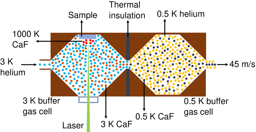
A novel two-stage helium buffer gas cooled beam source is introduced. The properties of the molecular beams produced from this source are investigated theoretically using the CaF as a test molecule. The gas-phase molecules are first produced inside a 3 K helium buffer gas cell by laser ablation and subsequently cooled down to 3 K by collisions with buffer gas atoms. The precooled molecules are then extracted into the 0.5 K helium buffer gas cell where they are cooled further down to 0.5 K by collisions with cold helium atoms. Finally, the cold molecules are extracted out into the high vacuum through the 0.5 K cell exit aperture and form a molecular beam. The mean forward velocity and the beam flux are calculated to be 45 m/s and 81012 molecules per pulse respectively when both cells are operated in the so-called hydrodynamic entrainment regime. Using this flux and Maxwell-Boltzmann probability density function at 0.5 K, the number of the molecules moving with speeds 5 m/s is calculated to be 8109. These slow and intense beams of the cold molecules are beneficial for efficient magneto-optical trapping of the molecules, investigating sympathetic cooling of the molecules with ultracold atoms, and performing ultrahigh precision molecular spectroscopy.
I Introduction
The collisions of the cold buffer gas atoms with warm molecules cool their translational and rotational temperatures Weinstein et al. (1998); Hutzler et al. (2012); Singh et al. (2012). Thus, cryogenic helium buffer gas-cooled beams are prerequisite for the laser cooling of the molecules Anderegg et al. (2017); Shuman et al. (2010). Further, the number of photon absorption and emission cycles required for the laser cooling of atoms and molecules decrease with their forward velocity and hence the laser cooling efficiency of the molecules increases with decrease in their forward velocity Anderegg et al. (2017); Kozyryev et al. (2017); Williams et al. (2018); Shuman et al. (2010); Zhelyazkova et al. (2014). In addition to this, the slower beams are also beneficial for efficient deceleration of the atoms and molecules by moving trap decelerators Lavert-Ofir et al. (2011); McArd et al. ; Quintero-Pérez et al. (2013). This is because the reduced initial velocity facilitates in producing deeper traps. This results in increased velocity acceptance and hence the overall efficiency of the decelerator. Furthermore, the intense and slow beams of buffer gas-cooled molecules increase the product , where is the total number of molecules that participate in the experiments and is the measurement time. Consequently, they enhance the statistical sensitivity of the ultrahigh precision measurements Hudson et al. (2011); Collaboration et al. (2014); Quack (1986); Tokunaga et al. (2017); Kozyryev and Hutzler (2017).
To extract the maximum number of molecules from the buffer gas cell into the molecular beam, the buffer gas cell is operated in the so-called hydrodynamic entrainment regime Hutzler et al. (2012); Patterson and Doyle (2007). This regime occurs at higher buffer gas densities such that the collisions of the buffer gas atoms at the cell exit boost the mean velocity of the molecules as high as the mean forward velocity () of the buffer gas atoms. Where is Boltzmann constant, and and are the temperature and mass of the buffer gas atoms respectively. This boosting can however be suppressed partially by collisions of the molecules with buffer gas atoms inside a low buffer gas density slowing cell attached to the main buffer gas cell Anderegg et al. (2017); Lu et al. (2011). But due to the accelerated diffusion losses inside the low-density buffer gas cell, the fraction of the molecules extracted from the cell into the molecular beam is reduced by several orders of magnitude Patterson and Doyle (2007); Lu et al. (2011).
This paper introduces a new approach for reducing the forward velocity of the buffer gas-cooled beams without compromising the flux of molecules. Our approach is based on operating the buffer gas cell at the lowest temperature for minimizing the boosting of the molecules. At 0.5 K, the calculated mean forward velocity of the helium atoms is 45 m/s and hence the mean forward velocity of the helium buffer gas-cooled molecules can be reduced to 45 m/s by lowering the buffer gas cell temperature down to 0.5 K, even though the cell is operated in hydrodynamic entrainment regime. Furthermore, as discussed in subsection VI.1, the Maxwell-Boltzmann probability density function (PDF) of slower buffer gas atoms increases rapidly with decrease in temperature and hence the flux of the buffer gas-cooled molecules moving with speeds 5 m/s is enhanced by a factor of 25 when the buffer gas cell temperature is lowered from 4 K to 0.5 K. This enhancement in the flux of the slower molecules is beneficial for efficient loading of the molecules into a magneto-optical trap Anderegg et al. (2017); Williams et al. (2018), investigating sympathetic cooling of buffer gas-cooled molecules with ultracold atoms Lim et al. (2015), and performing ultrahigh precision molecular spectroscopy Hudson et al. (2011); Collaboration et al. (2014); Quack (1986); Tokunaga et al. (2017); Kozyryev and Hutzler (2017).
Using the 4He as a buffer gas, a density of 1015 cm-3 can be achieved at 0.5 K cell temperature Pobell (2007); Friedrich et al. (1998). While this density is sufficient for the buffer gas cooling of the atoms and molecules, the heat load on the buffer gas cell from the vaporization techniques such as laser ablation usually exceeds the cooling power of the evaporation refrigerators at 0.5 K Anderegg et al. (2017); Singh et al. (2012). To implement this new approach, avoiding the heat load on the 0.5 K stage of the helium buffer gas cell from the laser ablation is therefore a prerequisite. This can be achieved by using a novel two-stage helium buffer gas cooling technique introduced here.
The first stage helium buffer gas cell is attached to the second stage of the cryogenic refrigerator and cooled below 3 K Singh et al. (2012, 2018). On the other hand, the second stage buffer gas cell is attached to the 3He bath and cooled down to 0.5 K by evaporative cooling Anderegg et al. (2017); Singh et al. (2012). Due to the significantly higher vapor pressure of the 3He compared to 4He at low temperatures Pobell (2007); Huang and Chen (2006), a higher cooling power can be achieved by pumping on a 3He bath at 0.5 K 111From the relation, , the cooling power of an evaporation refrigerator is proportional to the vapor pressure (P). To achieve higher cooling power at low temperatures, a 3He evaporation refrigerator is preferred over that 4He. Further, the evaporation refrigerators are operated in closed cycles and hence there is no 3He consumption. This brings down the operational cost of a 3He refrigerator similar to that of a 4He refrigerator. Currently, 4He evaporation refrigerators are operating at the Harvard University and the University of the Nevada Reno (UNR). The technical challenges of developing such refrigerators have already been overcome Singh et al. (2012)..
The molecules are first vaporized and cooled down to 3 K inside the first stage helium buffer gas cell 222The second stage of the cryogenic refrigerator (CRYOMECH:PT420) has a cooling power of 2 W at 4.2 K (http://www.cryomech.com/cryorefrigerators/pulse-tube/). As shown in the Section VI, the total heat load on the second stage of the cryogenic refrigerator is much smaller than this cooling power.. These precooled molecules are then extracted into the second stage where they are further cooled down to 0.5 K by collisions with buffer gas atoms. The heat load on the 0.5 K helium buffer gas cell is therefore reduced well below the cooling power of the 3He evaporation refrigerator at 0.5 K 333As shown in the Section VI, the calculated heat load on the 3He evaporatiion refrigerator stays below 1 mW, when the beam source is operated with a repetition rate of 20 Hz.
Our calculations demonstrate that for typically used buffer gas cell parameters and helium flow rates, the loss of the molecules inside the buffer gas cells can be minimized and hence a maximum number of the cold molecules can be extracted from the buffer gas cells into the molecular beam. The flux of the cold molecules produced from this source is calculated using the experimental values of the number of the CaF molecules produced by laser ablation and extraction efficiency the molecules from the buffer gas cell. On the other hand, the forward and transverse velocities of the molecules are calculated from the buffer gas temperature. The relevant equations are simplified and can be utilized straightforwardly for investigating the properties of buffer gas-cooled beams of any small molecule in the gas phase Hutzler et al. (2012); Kozyryev et al. (2017); Piskorski et al. (2014).
II First stage buffer gas cooling of the molecules
As shown in Figure 1, the gas-phase molecules are produced inside the first stage helium buffer gas cell via laser ablation of a solid CaF2 precursor and subsequently cooled down to 3 K by collisions with helium atoms. These precooled molecules are first extracted into the second stage helium buffer gas cell and subsequently cooled down to 0.5 K by collisions with cold helium atoms. To extract the maximum number of the molecules into the 0.5 K buffer gas cell, the 3 K buffer gas cell is operated in the hydrodynamic entrainment regime. As discussed in subsection VI.2, the buffer gas cells with conical geometries are used for circumventing the formation of the vortices in the helium flow. Thus, the diffusion losses due to the trapping of the molecules in the vortices are suppressed and hence the flux of the buffer gas-cooled molecules is further enhanced (Singh et al., 2018).
The initial temperature of the CaF is assumed to be 1000 K. Using the hard sphere collision model, the number of collisions required to thermalize the CaF molecules with 3 K 4He buffer gas can be estimated from Equation 1 Hutzler et al. (2012).
| (1) |
Where is the temperature of the molecules after collisions with buffer gas atoms, is the buffer gas temperature, is the initial temperature of the molecules, , and and are the masses of the molecule and buffer gas atoms respectively. For thermalizing the CaF molecules with 3 K 4He buffer gas atoms only 100 collisions are sufficient.
The length () required to thermalize the molecules with the buffer gas is related to the number of collisions () and the mean free path (, by the Equation 2.
| (2) |
Where is the collision cross-section of molecules with the buffer gas atoms and is the buffer gas density.
In steady-state, the buffer gas density inside the cell is related to the buffer gas flow rate by the Equation 3 Hutzler et al. (2012).
| (3) |
Where is the area of the cell exit aperture. The is mean thermal velocity of the buffer gas atoms and is given by the following equation.
| (4) |
The is the Boltzmann constant. Using Equation 3 and Equation 4, the 4He buffer gas density inside the first stage of the buffer gas cell can be estimated from Equation 5.
| (5) |
Where SCCM stands for standard cubic centimeter per minute. For the buffer gas flow rate of 10 SCCM and the cell with an exit aperture of 4 mm diameter, the calculated buffer gas density inside the cell is 1.21016 cm-3. Using Equation 2 and Equation 5, the thermalization length of the molecules with the 4He buffer gas can be given by the Equation 6.
| (6) |
Here is assumed to be 10-14 cm2 Hutzler et al. (2012). As expected the thermalization length decreases with increase in flow rate. For the helium flow rate of 12 SCCM, the length () required to thermalize the molecules with the 3 K helium buffer gas is 0.5 cm. Thus, a few cm long helium buffer gas cell should be sufficient for the first stage buffer gas cooling of molecules.
The number of the molecules extracted from the buffer gas cell into the molecular beam are characterized by the cell extraction parameter (), where is the diffusion time of the molecules to the cold cell walls and is the typical time spent by the molecules inside the buffer gas cell. For our first stage buffer gas cell, the can be estimated from the Equation 7 Hutzler et al. (2012).
| (7) |
For our helium buffer gas cell length () of 4 cm, and buffer gas flow rate of 12 SCCM, 1.1. Thus, the cell will operate in hydrodynamic entrainment regime ( 1).
It has been observed in previous experiments that the number of CaF molecules as high as 1013 can be produced in each ablation pulse Maussang et al. (2005). In addition to this, the extraction of over 40 of the buffer gas-cooled molecules from the buffer gas cell into the molecular beam has been observed Patterson and Doyle (2007), when the buffer gas cell is operated in hydrodynamic entrainment regime. With this extraction efficiency, the number of the buffer gas-cooled molecules transmitted through the 3 K buffer gas cell exit aperture are 2 1013 per pulse. This extraction of the molecules can be further increased by using an optimized buffer gas cell geometry Singh et al. (2018).
Owing to their larger mass, the mean thermal velocity of the CaF molecules inside the buffer gas cell is smaller than that of the buffer gas atoms. At the cell exit, the collisions of the buffer gas atoms boost the mean forward velocity of the molecules. The number of collision between the molecules and buffer gas atoms can be estimated from Equation 8 Hutzler et al. (2012).
| (8) |
Where is the diameter of cell exit aperture and is the Reynolds number. Using Equation 2, Equation 3, and Equation 8, the Reynolds number can be given by the following equation.
| (9) |
The Reynolds number increases with buffer gas flow rate. For the helium flow rate of 12 SCCM, the Reynolds number 100. At the cell exit, the number of collisions of molecules with buffer gas are 50. In each collision with buffer gas atom, the change in the forward momentum of the molecules . Thus, the corresponding change in the forward velocity () of the molecules can be estimated from Equation 10.
| (10) |
The number of collisions between the molecules and the buffer gas atoms increase with buffer gas flow rate. At 12 SCCM helium flow rate, the forward velocity of the molecules is expected to be boosted to the forward velocity () of the buffer gas atoms, i.e. 110 m/s.
Further, the transverse velocity of the buffer gas inside the cell () can be approximated by Equation 11 Hutzler et al. (2011).
| (11) |
Where is the cell diameter. For the helium buffer gas cell with 50 mm diameter, 0.8 m/s. The change in the transverse velocity () of the molecules due to the collisions with buffer gas atoms at the cell exit can be estimated from Equation 12.
| (12) |
The change in the transverse velocity of the molecules also increases with increase in the buffer gas flow rate. At 12 SCCM, the change in transverse velocity 2.4 m/s. Assuming a 4 mm initial beam spread (size of the exit aperture), the calculated transverse molecular beam spread 1 cm away from the first stage buffer gas cell exit 4.4 mm 444The time taken by the beam in traveling 1 cm is 0.09 ms. The transverse distance traveled by the beam during this time is 0.2 mm.. Thus, using a 5 mm diameter entrance aperture, all the precooled CaF molecules transmitted from the first stage buffer gas cell can be extracted into the second stage buffer gas cell. The distance between the cells can indeed be optimized for extracting the maximum number of the molecules from first stage buffer gas cell into the second stage buffer gas cell.
III Second stage buffer gas cooling of the molecules
To suppress the diffusion losses and hence extracting the maximum number of the molecules from the cell into the molecular beam, the 0.5 K helium buffer gas cell is also operated in the hydrodynamic entrainment regime. From Equation 1, the number of collisions of the CaF molecules with helium buffer gas atoms required to cool them from 3 K down to 0.5 K is 50. For a helium flow rate of 5 SCCM and the cell exit aperture of 6 mm diameter, the thermalization length of the molecules with the 0.5 K helium buffer gas calculated using Equation 6 is 0.6 cm. For this flow, the helium buffer gas density estimated from Equation 5 is 6 1015 cm-3.
With a helium buffer gas length of 3 cm, the calculated extraction parameter is 1.5. Thus, the cell will operate in hydrodynamic entrainment regime and over 40 of the buffer gas-cooled molecules out of the 2 1013 can be extracted from the cell into the beam Patterson and Doyle (2007). Thus, the flux of produced CaF molecules per pulse is 81012. It is worth mentioning that the flux of the cold atoms and molecules produced from a buffer gas-cooled beam source largely depends on the vaporization yield. It has been observed that the high purity (99.9%) solid precursors yield higher fluxes of cold atoms and molecules as compared to the smaller purity (95%) precursors Maussang et al. (2005); Singh et al. (2012).
On the other hand, the mean forward velocity of the molecules in the beam depends upon the buffer gas temperature and the number of the collisions of molecules with the buffer gas atoms at the cell exit aperture. For the second stage helium buffer gas cell parameters, the estimated Reynolds number from Equation 9 is 70. The number of collisions of molecules with buffer gas atoms is 35. From Equation 10, it is clear that these collisions are sufficient to boost the forward velocity of the molecular beam to the forward velocity () of the buffer gas atoms. At 0.5 K, the CaF will acquire a mean forward velocity of 45 m/s.
As discussed in subsection VI.1, at 0.5 K, the Maxwell-Boltzmann PDF of the helium atoms moving with speeds 5 m/s is 0.001. In the hydrodynamic entrainment regime, the velocity distribution of the molecules is similar to that of the buffer gas atoms. Thus, the flux of the CaF moving with speeds 5 m/s is 8109 molecules per pulse. These very slow and intense beams of the cold molecules can be directly loaded into a magneto-optical trap and hence paving the way for efficient laser cooling of the molecules Anderegg et al. (2017); Williams et al. (2018). In addition to this, these very slow and high flux beams of the molecules can be utilized for investigating the sympathetic cooling of the buffer gas-cooled molecules with ultracold atoms Lim et al. (2015). Furthermore, such very slow and intense beams of the buffer gas-cooled molecules can also be utilized for searching the electric dipole moment of the electron (Collaboration et al., 2014; Hudson et al., 2011) and measurements of the parity-violating energy difference between enantiomers of the chiral molecules (Quack, 1986; Tokunaga et al., 2017).
IV Conclusion
In conclusion, a novel two-stage buffer gas-cooled beam source is introduced. The vaporization and precooling of the molecules inside the first stage 3 K helium buffer gas cell suppresses the heat load on the second stage and hence facilitates the operation of the second stage buffer gas cell at 0.5 K with the repetition rates over 20 Hz. At this temperature, the mean forward velocity and the flux of the CaF beam are calculated to be 45 m/s and 8 molecules per pulse respectively, when both buffer gas cells are operated in the hydrodynamic entrainment regime. Using this flux and Maxwell-Boltzmann PDF at 0.5 K, the number of the molecules moving with speeds 5 m/s is calculated to be 8. These very slow and intense beams of the cold molecules produced from our two-stage buffer gas-cooled beam source can be utilized for a wide diversity of molecular physics experiments such as efficient magneto-optical trapping of the molecules and performing ultrahigh precision molecular spectroscopy.
V Acknowledgements
This work is supported by the National Science Centre, Poland, Project No. 2017/25/B/ST2/00429.
References
- Weinstein et al. (1998) Jonathan D. Weinstein, Robert deCarvalho, Thierry Guillet, Bretislav Friedrich, and John M. Doyle, “Magnetic trapping of calcium monohydride molecules at millikelvin temperatures,” Nature 395, 148–150 (1998).
- Hutzler et al. (2012) N. R. Hutzler, H.-I Lu, and J. M. Doyle, “The buffer gas beam: An intense, cold, and slow source for atoms and molecules,” Chem. Rev. 112, 4803 (2012).
- Singh et al. (2012) Vijay Singh, Kyle S. Hardman, Naima Tariq, Mei-Ju Lu, Aja Ellis, Muir J. Morrison, and Jonathan D. Weinstein, “Chemical reactions of atomic lithium and molecular calcium monohydride at 1 K,” Phys. Rev. Lett. 108, 203201 (2012).
- Anderegg et al. (2017) Loïc Anderegg, Benjamin L. Augenbraun, Eunmi Chae, Boerge Hemmerling, Nicholas R. Hutzler, Aakash Ravi, Alejandra Collopy, Jun Ye, Wolfgang Ketterle, and John M. Doyle, “Radio frequency magneto-optical trapping of CaF with high density,” Phys. Rev. Lett. 119, 103201 (2017).
- Shuman et al. (2010) E. S. Shuman, J. F. Barry, and D. DeMille, “Laser cooling of a diatomic molecule,” Nature 467, 820–823 (2010).
- Kozyryev et al. (2017) Ivan Kozyryev, Louis Baum, Kyle Matsuda, Benjamin L. Augenbraun, Loic Anderegg, Alexander P. Sedlack, and John M. Doyle, “Sisyphus laser cooling of a polyatomic molecule,” Phys. Rev. Lett. 118, 173201 (2017).
- Williams et al. (2018) H. J. Williams, L. Caldwell, N. J. Fitch, S. Truppe, J. Rodewald, E. A. Hinds, B. E. Sauer, and M. R. Tarbutt, “Magnetic trapping and coherent control of laser-cooled molecules,” Phys. Rev. Lett. 120, 163201 (2018).
- Zhelyazkova et al. (2014) V. Zhelyazkova, A. Cournol, T. E. Wall, A. Matsushima, J. J. Hudson, E. A. Hinds, M. R. Tarbutt, and B. E. Sauer, “Laser cooling and slowing of CaF molecules,” Phys. Rev. A 89, 053416 (2014).
- Lavert-Ofir et al. (2011) Etay Lavert-Ofir, Sasha Gersten, Alon B Henson, Itamar Shani, Liron David, Julia Narevicius, and Edvardas Narevicius, “A moving magnetic trap decelerator: a new source of cold atoms and molecules,” New J. Phys. 13, 103030 (2011).
- (10) Lewis A. McArd, Arin Mizouri, Paul A. Walker, Vijay Singh, Ulrich Krohn, Ed A. Hinds, and David Carty, “A moving-trap zeeman decelerator,” preprint at arXiv:1807.10648 .
- Quintero-Pérez et al. (2013) Marina Quintero-Pérez, Paul Jansen, Thomas E. Wall, Joost E. van den Berg, Steven Hoekstra, and Hendrick L. Bethlem, “Static trapping of polar molecules in a traveling wave decelerator,” Phys. Rev. Lett. 110, 133003 (2013).
- Hudson et al. (2011) J. J. Hudson, D. M. Kara, I. J. Smallman, B. E. Sauer, M. R. Tarbutt, and E. A. Hinds, “Improved measurement of the shape of the electron,” Nature 473, 493–496 (2011).
- Collaboration et al. (2014) ACME Collaboration, J. Baron, W. C. Campbell, D. DeMille, J. M. Doyle, G. Gabrielse, Y. V. Gurevich, P. W. Hess, N. R. Hutzler, E. Kirilov, I. Kozyryev, B. R. O’Leary, C. D. Panda, E. S. Petrik, B. Spaun, A. C. Vutha, and A. D. West, “Order of magnitude smaller limit on the electric dipole moment of the electron,” Science 343, 269–272 (2014).
- Quack (1986) Martin Quack, “On the measurement of the parity violating energy difference between enantiomers,” Chem. Phys. Lett. 132, 147 – 153 (1986).
- Tokunaga et al. (2017) S K Tokunaga, R J Hendricks, M R Tarbutt, and B Darquié, “High-resolution mid-infrared spectroscopy of buffer-gas-cooled methyltrioxorhenium molecules,” New J. Phys. 19, 053006 (2017).
- Kozyryev and Hutzler (2017) Ivan Kozyryev and Nicholas R. Hutzler, “Precision measurement of time-reversal symmetry violation with laser-cooled polyatomic molecules,” Phys. Rev. Lett. 119, 133002 (2017).
- Patterson and Doyle (2007) David Patterson and John M. Doyle, “Bright, guided molecular beam with hydrodynamic enhancement,” J. Chem. Phys. 126, 154307 (2007).
- Lu et al. (2011) Hsin-I Lu, Julia Rasmussen, Matthew J. Wright, Dave Patterson, and John M. Doyle, “A cold and slow molecular beam,” Phys. Chem. Chem. Phys. 13, 18986–18990 (2011).
- Lim et al. (2015) Jongseok Lim, Matthew D. Frye, Jeremy M. Hutson, and M. R. Tarbutt, “Modeling sympathetic cooling of molecules by ultracold atoms,” Phys. Rev. A 92, 053419 (2015).
- Pobell (2007) Frank Pobell, Matter and methods at low temperatures, 3rd ed. (Springer, 2007).
- Friedrich et al. (1998) Bretislav Friedrich, Robert deCarvalho, Jinha Kim, David Patterson, Jonathan D. Weinstein, and John M. Doyle, “Towards magnetic trapping of molecules,” J. Chem. Soc., Faraday Trans. 94, 1783–1791 (1998).
- Singh et al. (2018) Vijay Singh, Amit K. Samanta, Nils Roth, Daniel Gusa, Tim Ossenbrüggen, Igor Rubinsky, Daniel A. Horke, and Jochen Küpper, “Optimized cell geometry for buffer-gas-cooled molecular-beam sources,” Phys. Rev. A 97, 032704 (2018).
- Huang and Chen (2006) Y.H. Huang and G.B. Chen, “A practical vapor pressure equation for helium-3 from 0.01 K to the critical point,” Cryogenics 46, 833 – 839 (2006).
- Note (1) From the relation, , the cooling power of an evaporation refrigerator is proportional to the vapor pressure (P). To achieve higher cooling power at low temperatures, a 3He evaporation refrigerator is preferred over that 4He. Further, the evaporation refrigerators are operated in closed cycles and hence there is no 3He consumption. This brings down the operational cost of a 3He refrigerator similar to that of a 4He refrigerator. Currently, 4He evaporation refrigerators are operating at the Harvard University and the University of the Nevada Reno (UNR). The technical challenges of developing such refrigerators have already been overcome Singh et al. (2012).
- Note (2) The second stage of the cryogenic refrigerator (CRYOMECH:PT420) has a cooling power of 2 W at 4.2 K (http://www.cryomech.com/cryorefrigerators/pulse-tube/). As shown in the Section VI, the total heat load on the second stage of the cryogenic refrigerator is much smaller than this cooling power.
- Note (3) As shown in the Section VI, the calculated heat load on the 3He cryogenic refrigerator stays below 1 mW, when the beam source is operated with a repetition rate of 20 Hz.
- Piskorski et al. (2014) Julia Piskorski, David Patterson, Sandra Eibenberger, and John M. Doyle, “Cooling, spectroscopy and non-sticking of trans-stilbene and nile red,” ChemPhysChem 15, 3800–3804 (2014).
- Maussang et al. (2005) Kenneth Maussang, Dima Egorov, Joel S. Helton, Scott V. Nguyen, and John M. Doyle, “Zeeman relaxation of CaF in low-temperature collisions with helium,” Phys. Rev. Lett. 94, 123002 (2005).
- Hutzler et al. (2011) Nicholas R. Hutzler, Maxwell F. Parsons, Yulia V. Gurevich, Paul W. Hess, Elizabeth Petrik, Ben Spaun, Amar C. Vutha, David DeMille, Gerald Gabrielse, and John M. Doyle, “A cryogenic beam of refractory, chemically reactive molecules with expansion cooling,” Phys. Chem. Chem. Phys. 13, 18976–18985 (2011).
- Note (4) The time taken by the beam in traveling 1 cm is 0.09 ms. The transverse distance traveled by the beam during this time is 0.2 mm.
- (31) COMSOL Multiphysics v. 5.3. http://www.comsol.com. COMSOL AB, Stockholm, Sweden.
- Note (5) This heat load is calculated using the literature value of the CaF2 specific heat of 854 J Kg-1 K-1 (https://www.crystran.co.uk/optical-materials/calcium- fluoride-caf2).
VI Appendix
This section presents the calculations of the Maxwell-Boltzmann PDF of the speeds of the helium atoms at low temperatures, simulation of helium behavior inside the buffer gas cells, and the required helium flow rate for 10 mW cooling power of the helium bath. The Maxwell-Boltzmann PDF of helium atoms indicates that the fraction of the molecules moving with speeds below 10 m/s can be significantly enhanced by lowering the cell temperature. Furthermore, the simulated helium behavior inside the buffer gas cells shows that the diffusion losses to the cold cell walls can be minimized by using the buffer gas cells with conical geometry. On the other hand, the calculated heat loads on the first and second stages of the cryogenic refrigerator as well as on the 3He bath are well below their corresponding cooling powers. Thus, it is technically feasible to design a two-stage buffer gas-cooled beam source with the parameters considered here.
VI.1 Maxwell-Boltzmann probability density function of helium atoms at low temperatures
For helium buffer gas atoms, we have calculated the Maxwell-Boltzmann PDF, f, using the following equation.
| (13) |
The calculated PDF for helium atoms moving with a speed below 10 m/s at low temperatures is shown in Figure 2. As expected, the fraction of the slower molecules increases rapidly with decrease in temperature.
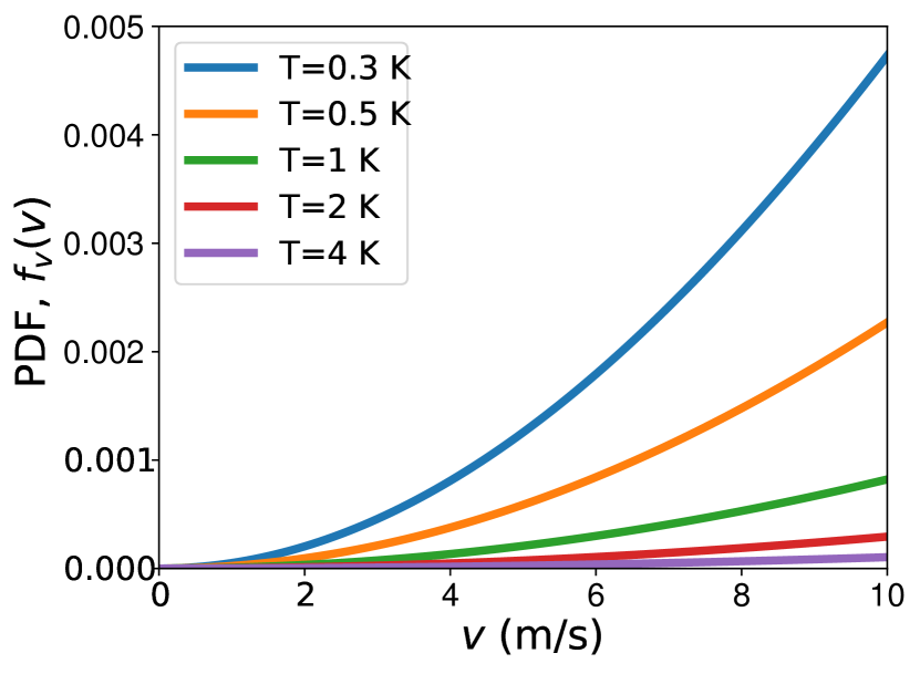
The calculated sums of the PDFs for 0 - 5 m/s, 0 - 10 m/s, 0 - 20 m/s, and 0 - 50 m/s speed ranges at low temperatures ranging from 0.3 K to 4 K are shown in Table 1. In the hydrodynamic entrainment regime, the speed distribution of the buffer gas cooled molecules is similar to that of buffer gas atoms. Thus, these PDF values are used for calculating the flux of the slower molecules in the molecular beams produced from our two-stage buffer gas cooled beam source. The total flux of the CaF produced from this source is 8 1012 molecules per pulse. Using this flux and PDF values of helium at 0.5 K, the flux of the CaF moving with speeds below 5 m/s, 10 m/s, 20 m/s, and 50 m/s are calculated to be 8 109, 6 1010, 4 1011, and 4 1012 molecules per pulse respectively.
| T (K) | f(0-5 m/s) | f(0-10 m/s) | f(0-20 m/s) | f(0-50 m/s) |
|---|---|---|---|---|
| 0.3 | 0.002 | 0.02 | 0.11 | 0.74 |
| 0.5 | 0.001 | 0.008 | 0.06 | 0.51 |
| 1 | 0.0004 | 0.003 | 0.02 | 0.3 |
| 2 | 0.0001 | 0.001 | 0.008 | 0.1 |
| 4 | 0.00004 | 0.0004 | 0.003 | 0.04 |
VI.2 Simulation of helium behavior inside the buffer gas cells
To determine the optimum geometry of our buffer gas cells, we have simulated the helium flow-fields inside the buffer gas cells using a finite-element solver, COMSOL Multiphysics with laminar flow interface Com , treating helium as an ideal gas in the temperature range 3-0.5 K. For 12 SCCM of helium flow and a pressure of mbar outside the cell exit, the resulting flow fields are shown in Figure 3 as slices through the cylindrically-symmetric cell volume, i.e., in space.
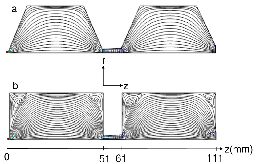
From the simulations, we have extracted the helium pressures inside the cells. These extracted values are shown in Table 2 and are in a good qualitative agreement with the calculations.
| region | pressure (mbar) | density (cm-3) |
|---|---|---|
| 3 K cell ( = 1 to = 51) | 0.03 | 7.21016 |
| between the cells ( = 51 to = 61) | 0.02 | 4.81016 |
| 0.5 K cell ( = 61 to = 111) | 0.003 | 4.31016 |
| 0.5 K cell exit ( = 111) | 0.002 | 2.81016 |
Furthermore, the simulations show that the planar cell geometries produce vortices in the flow fields at the cell corners. This can be circumvented by the use of conical cell geometry, which results in an overall laminar flow. The hot CaF molecules introduced into the cell are thermalized with the buffer-gas before reaching to cell exit and hence follow the streamlines. The presence of vortices in the flow-field can therefore lead to trapping of the molecules and eventually loss to the cell walls. On the other hand, the laminar flow produced by a conical cell geometry avoids these diffusion losses and, therefore, allows entraining maximum number of the molecules into the beam (Singh et al., 2018). Thus, the buffer gas cells with conical extrance and conical exit are beneficial for extracting the maximum number of the molecules from the proposed two-stage buffer gas-cooled beam source.
VI.3 Calculated mass flow rate for 10 mW cooling power of the helium bath
At 0.5 K, the 3He vapor pressure = 0.2 mbar Pobell (2007); Huang and Chen (2006). The latent heat of vaporization of the 3He is = 8.5 J/gm at 3.2 K temperature and 1 bar pressure. One gram of 3He contains 2 1023 atoms.
Thus, the latent heat of vaporization = 4.25 10-23 J/atom. The number of atoms () contained by 1 L of 3He at = 0.5 K and = 0.2 mbar can be calculated from the ideal gas law . = (0.2 mbar)(1 L)/((1.38 10-23 J/K)(0.5 K)) = (20 Pa)(0.001 m3)/((1.38 10-23 J/K)(0.5 K)) = 30 1020. Thus, at = 0.5 K and = 0.2 mbar, = (4.25 10-23 J/atom) (30 1020 atom/L) = 0.13 J/L.
To achieve a cooling power of 10 mW, the boil off rate = (10 mW/0.13 J/L) = 0.078 L/s. Operating the refrigerator continuously, the liquid 3He flow into the helium bath must be equal to the boil off rate. Thus, the required flow through the helium condenser (3 K, 1 bar) calculated using ideal gas law = (0.2 mbar/1 bar) (3 K/0.5 K) (0.078 L/s)= 9.4 10-5 L/s. At = 3 K and = 1 bar, this corresponds to a gas flow of = (100000 Pa)(9.4 10-5 L/s)(0.001 m3/L)/ ((1.38 10-23 J/K) (3 K)) = 2.3 1020 atom/s = (2.3 1020 atom/s) (1 gm/2 1023 atom) = 1.2 mg/s.
VI.4 Calculated heat load on the first stage of the refrigerator
At the first stage both 3He (evaporated from the helium bath) and 4He (used for helium buffer gas cooling) are required to be cooled down from 300 K to 30 K. The 3He mass flow rate = 1.2 mg/s. The 4He flow rate = 20 SCCM (over estimated) = (20 4.5 1017)(4 gm/s)/(6.023 1023) = 0.06 mg/s. The total heat load on the first stage of the cryogenic refrigerator = ((1.2 + 0.06) mg/s)(5.2 J/(gm K))(270 K) = 1.8 W. This load is much smaller than the cooling power (55 W at 45 K) of the cryogenic refrigerator (CRYOMECH: PT420).
VI.5 Calculated heat load on the second stage of the refrigerator
At the second stage, the 3He required to cool from 30 to 3 K and convert from gas to liquid, the 4He needs to be cooled from 30 to 3 K, and molecules are vaporized by 10 mJ laser pulse with 20 Hz repetition rate by laser ablation in the first stage of the buffer gas cell attached to the second stage. The the total heat load on the second stage = (1.2 mg/s)(5.2 J/(gm K))(27 K) + (1.2 mg/s)(8.5 J/gm) + (0.06 mg/s)(5.2 J/(gm K))(27 K) + (10 mJ)(20 pulse/s) = 0.4 W. This heat load is significantly smaller compared to the second stage cooling power (2 W at 4.2 K) of the cryogenic refrigerator.
VI.6 Calculated heat load on the 0.5 K stage of the buffer gas cell
The 20 SCCM flow from the first stage of the buffer gas cell required to be cooled down from 3 K to 0.5 K on the second stage of the buffer gas cell attached to the helium bath. Thus, the heat load on the 0.5 K helium bath = (0.06 mg/s)(5.2 J/(gm K))(2.5 K) = 0.8 mW. Further, the heat load from cooling of the 2 1013 CaF molecules from 3 K to 0.5 K with 20 Hz repetition rate is below 0.1 mW 555This heat load is calculated using the literature value of the CaF2 specific heat of 854 J Kg-1 K-1 (https://www.crystran.co.uk/optical-materials/calcium- fluoride-caf2) . Thus, the total heat load on the 0.5 K stage is much smaller compared to the targeted cooling power (10 mW) of the helium bath.