Alignment of the \ceCS2 Dimer Embedded in Helium Droplets Induced by a Circularly Polarized Laser Pulse
Abstract
Dimers of carbon disulfide (\ceCS2) molecules embedded in helium nanodroplets are aligned using a moderately intense, , non-resonant, circularly polarized laser pulse. It is shown that the intermolecular carbon-carbon (C-C) axis aligns along the axis perpendicular to the polarization plane of the alignment laser pulse. The degree of alignment, quantified by , is determined from the emission directions of recoiling \ceCS2+ fragment ions, created when an intense probe laser pulse doubly ionizes the dimers. Here, is the projection of the angle between the C-C axis on the 2D ion detector and the normal to the polarization plane. is measured as a function of the alignment laser intensity and the results agree well with calculated for gas-phase \ceCS2 dimers with a rotational temperature of .
I Introduction
Recently, it has been shown that techniques used to align gas-phase samples of molecules based on the application of moderately intense laser pulses can be transferred to molecules inside helium nanodroplets Pentlehner et al. (2013a, b); Shepperson et al. (2017a, b); Chatterley et al. (2017). This creates several new opportunities. Firstly, time-resolved imaging of molecular rotation, induced and probed by fs laser pulses makes it possible to investigate how rotational quantum coherence, angular momentum, and energy are influenced by a dissipative environment Pentlehner et al. (2013a); Shepperson et al. (2017a, 2018); Ramakrishna and Seideman (2005); Vieillard et al. (2008); Lindgren and Kiljunen (2013); Stickler et al. (2018); Schmidt and Lemeshko (2015); Lemeshko (2017). Secondly, the temperature of He droplets is shared with the molecules residing inside the droplets Toennies and Vilesov (2004). Such a low temperature is highly beneficial for creating very strong alignment – not just for small molecules Shepperson et al. (2017b) but also for larger species Chatterley et al. (2018), which can otherwise be difficult to effectively cool in the gas phase Meijer et al. (1990). Thirdly, the cold and dissipative environment of the He droplet provides unique opportunities for creating a variety of complexes of molecules and atoms Choi et al. (2006); Yang and Ellis (2012). Recently, it was shown that laser-induced alignment can also be applied efficiently to molecular complexes inside He droplets Pickering et al. (2018a, b). The high degrees of alignment made it possible to determine the structure of the molecular complexes by means of Coulomb explosion imaging induced by a high-intensity femtosecond laser pulse. Here we present a follow-up to our previous study of the \ceCS2 dimer Pickering et al. (2018b), examining the alignment behaviour of the dimer in more detail.
Alignment of molecules using linearly polarized laser pulses results in the confinement of the most polarizable axis of a molecule to the polarization axis of the aligning laser field and creates one-dimensional alignment Stapelfeldt and Seideman (2003). This has been the most common use of laser-induced alignment in many prior studies. The most polarizable axis provides a ‘handle’, which can be used to hold the molecule in advantageous spatial configurations using the alignment laser field Burt et al. (2018). However, it is also possible to align a molecule using a circularly (or elliptically) polarized laser field, which provides different handles and allows the molecule to be held in other spatial configurations than are possible with a linearly polarized field. Specifically, using a circularly polarized alignment field results in the alignment of the least polarizable molecular axis to the propagation axis of the alignment laser field Smeenk and Corkum (2013). This can be equivalently thought of as alignment of the most polarizable molecular plane to the polarization plane.
Our previous study of the \ceCS2 dimer solvated in He droplets Pickering et al. (2018b) showed that it was possible to form, align, and image \ceCS2 dimers inside He droplets. Analysis of the recoil directions of \ceCS2+ ions produced by Coulomb explosion of aligned \ceCS2 dimers showed that the structure of the \ceCS2 dimer in the He droplets was cross-shaped with symmetry - which is also the structure in the gas phase Moazzen-Ahmadi and McKellar (2013); Rezaei et al. (2011). Central to that study was the alignment of the \ceCS2 dimer (a symmetric top rotor) using a circularly polarized laser pulse. In the current work, we perform a detailed study of the intensity-dependent alignment of the \ceCS2 dimer in He droplets using a circularly polarized laser pulse. The alignment pulse duration of 160 ps places the alignment dynamics in the (quasi-) adiabatic regime. To our knowledge very few studies so far have addressed alignment of symmetric top molecules with a circularly polarized alignment pulse, and only in the nonadiabatic limit using femtosecond alignment pulses Smeenk and Corkum (2013); Smeenk et al. (2014).
II Background
II.1 Experimental Methods
The experimental setup used to align and image the \ceCS2 dimers has already been described in detail elsewhere Shepperson et al. (2017b); Pickering et al. (2018b), with only relevant details reiterated here. The \ceCS2 molecules were embedded in He droplets consisting of around 8000 He atoms on average. The droplets are passed through a pickup cell containing \ceCS2 vapor, and the partial pressure of \ceCS2 was adjusted to a regime where substantial amounts of dimers (but minimal amounts of larger clusters) were formed. This is defined as the dimer-doping-condition - in line with previous work Pickering et al. (2018b). The doped droplet beam is then intersected at by two focussed laser beams from the same Ti-Sapphire laser system. One beam consists of (FWHM) pulses ( = ) and is used to align the \ceCS2 dimers. The other beam consists of (FWHM) pulses ( = ), and is used to Coulomb explode the dimers. The intensity of the probe pulses was , and the intensity of the alignment pulses was varied, up to a maximum value of . The temporal overlap of the two pulses was such that the probe pulse arrived at the peak of the alignment pulse. The nascent \ceCS2+ ions were projected onto a 2D imaging detector using a VMI spectrometer, and ion images were recorded.
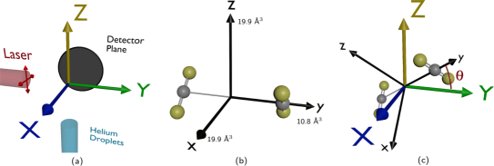
Before discussing the details of laser-induced alignment, it is important to define the molecular (x, y, z) and space-fixed (X, Y, Z) coordinate systems. Figure 1 (a) shows the space-fixed coordinate system. The laser beams propagate along the Y axis, such that the XZ plane is the polarization plane, and the He droplet beam propagates along the Z axis. Ions are accelerated along the X axis (the time-of-flight axis) towards a detector placed in the YZ plane. Figure 1 (b) shows the structure of the \ceCS2 dimer in its ground state geometry. The \ceCS2 dimer is a prolate symmetric top with a 90∘ angle between the two monomers, and in this case the symmetric top axis (the C-C axis) is placed along the y axis. The polarizability elements of the dimer are annotated on each molecular axis. In this case, the polarizability elements of the dimer were calculated simply by addition of the polarizability elements of the two monomers. This method neglects any orbital interaction between the two monomers, but will not qualitatively change the polarizability elements of the dimer, so is a reasonable first approximation to the true polarizability.
II.2 Alignment Theory
The methodology and theory for alignment of molecules induced by strong laser fields has been described in several reviews Stapelfeldt and Seideman (2003); Seideman and Hamilton (2005); Fleischer et al. (2012). Here we specifically consider the alignment of a symmetric top molecule using a circularly polarized laser pulse Smeenk and Corkum (2013); Smeenk et al. (2014). The interaction potential of a symmetric top molecule with a circularly polarized alignment field is given by Larsen (2000):
| (1) |
where is the electric field envelope of the alignment laser field; is the polarizability of the molecule parallel to the symmetric top axis; is the polarizability perpendicular to the symmetric top axis; and is the angle between the symmetric top axis and the normal to the polarization plane of the laser field. The alignment behaviour is determined by the sign of the polarizability anisotropy, - . If , which is typically the case for oblate symmetric top molecules like benzene (\ceC_6H_6), ammonia (\ceNH_3) or boron trifluoride (\ceBF_3), the potential is at a minimum when and the interaction between the laser field and the molecule should lead to alignment of the symmetric top axis along the normal vector of the polarization plane, i.e. the propagation direction of the laser field. This has been illustrated for benzene molecules using nonadiabatic alignment induced by a 250 fs alignment pulse Smeenk and Corkum (2013). In contrast, if , which is typically the case for prolate symmetric top molecules like methyl iodide (\ceCH3I) or acetonitrile (\ceCH_3CN), or for linear molecules, then the potential is at a minimum when . In this case the symmetric top axis will be confined to (but randomly oriented in) the polarization plane.
For the \ceCS2 dimer (Figure 1 (b)), although it is a prolate symmetric top. Thus, the expectation is that a circularly polarized alignment field will align the C-C axis (the y axis) along the propagation direction of the laser beam (the Y axis). A sketch of the combined space-fixed and molecule-fixed coordinate systems, and an illustration of the angle , is given in Figure 1 (c).
II.3 Computational Methods
Recently, angulon theory Lemeshko (2017); Schmidt and Lemeshko (2015) was used to rationalize that for the alignment pulse used here, alignment of \ceI2, 1,4-diiodobenzene, and 1,4-dibromobenzene molecules inside He droplets is well-described as alignment of gas-phase molecules with an effective rotational constant Shepperson et al. (2017b). Qualitatively, this can be understood using the fact that the turn-on time of the alignment pulse is longer than the timescale of the He-He interactions and the He-molecule interactions. Therefore, a molecule and its solvation shell of He atoms has time to adjust as the laser field increases in strength. The \ceCS2 dimer is expected to behave similarly and thus we apply gas-phase alignment theory to calculate the degree of alignment of the dimer induced by the circularly polarized alignment pulse. In practice, the calculations were performed using an alignment calculator previously developed in our group Søndergaard et al. (2017). This calculator solves the time-dependent rotational Schrödinger equation and returns the degree of alignment expressed as or . Here, is the angle between the projection of the molecular C-C axis on the detector plane and the laser propagation axis. Calculation of allows direct comparison of the calculations with the experimental data.
Strictly, the alignment calculator can only simulate alignment of linear or symmetric top molecules with using linearly polarized alignment fields where the interaction potential is given by Friedrich and Herschbach (1995):
| (2) |
Comparison of Equation 1 and Eq. 2 shows that for a symmetric top molecule where the angle-dependent part of the interaction potential induced by a circularly polarized field is the same as that for a linear molecule induced by a linearly polarized field. For the \ceCS2 dimer . This means that the alignment calculator can be used to calculate the degree of alignment of the \ceCS2 dimer induced by the circularly polarized field. We note that experimentally the peak intensity, , is determined. For a circularly polarized field the relation to the amplitude of the electric field, , is given by .
A detailed description of the alignment calculator can be found in reference Søndergaard (2016), with only relevant parameters mentioned here. Calculations were performed at a variety of ensemble temperatures (see later), using the experimentally measured Gaussian focal spot-sizes for both the alignment ( ) and probe ( ) beams. The degree of alignment was calculated using both the polarizability anisotropy determined by addition of the monomer polarizabilities (, ), and that calculated using density-functional theory (DFT - wB97XD/aug-pcseg-2) (, ) Pickering et al. (2018b). The effective rotational constant of a single \ceCS2 molecule inside He droplets has been calculated to be Zillich , where is the gas-phase rotational constant (). A similar reduction is assumed for the \ceCS2 dimer, thus the rotational constants used in the calculation are , , where is calculated around the molecular y axis, and and are calculated around the molecular x and z axes respectively. We note that in the (quasi-) adiatbatic limit defined by the pulses the degree of alignment is very insensitive to the rotational constant, being essentially only determined by the polarizability anisotropy, rotational temperature of the molecular ensemble and the intensity of the alignment pulse Seideman (2001).
III Results
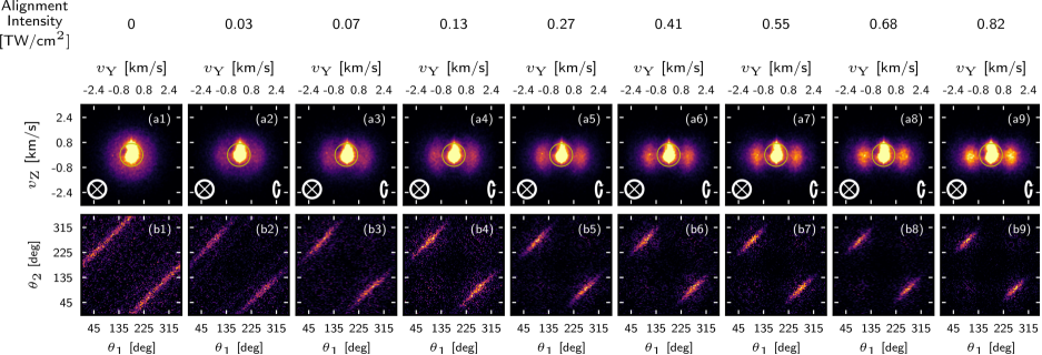
Each column of Fig. 2 shows both a \ceCS2+ ion image (row (a)), and corresponding angular covariance map (row (b)). The angular covariance map Hansen et al. (2012) was calculated over all ion hits outside of the annotated yellow circle on the ion image - this ensures that the covariance map is calculated using ion events arising from the Coulomb explosion of \ceCS2 dimers - as discussed in previous work Pickering et al. (2018b). The Coulomb explosion channel considered here is the one resulting from repulsion of two \ceCS2+ ions created when each of the two \ceCS2 molecules in the dimer are singly ionized by the probe laser pulse. The ion signal inside the yellow circle arises from single ionization of \ceCS2 monomers. In all images, the probe pulse was linearly polarized along the X axis (shown in the lower left corner of each ion image), and the alignment pulse was circularly polarized in the XZ plane (shown in the lower right corner of each ion image). The alignment intensity used to record each image is shown above each column, and was incremented from (column 1) to (column 9).
The ion signal outside the annotated yellow circle in images (a1)-(a9) of Fig. 2 moves from being isotropic (a1), to being strongly confined along the Y axis (a9) as the alignment intensity is increased from zero to its maximum value. This confinement is also reflected in the corresponding angular covariance maps (b1)-(b9), where the covariance signal changes from being a uniform line centered at or at (panel (b1)), to a confined island centered at (,), and the equivalent island at (,) (panel (b9)). It is clear from both the ion images and covariance maps that the degree of alignment increases as the alignment intensity is increased from column (1) to column (9), and that the degree of alignment appears to saturate at around column (5) - increasing the intensity beyond this level does not seem to dramatically increase the observed degree of alignment. This can be quantified by calculating - but it is useful to first consider the explosion process in He droplets in more detail.
Prior studies of aligned molecules in He droplets have shown that the recoil trajectories of the nascent ion fragments following Coulomb explosion are distorted due to scattering off the He atoms as they exit the droplet. This results in Non-Axial Recoil (NAR), where the recoil trajectories of the nascent ions no longer directly reflect the alignment of the molecular axis they recoiled from. In studies of laser-induced alignment inside He droplets, calculating from an ion image without correcting for NAR leads to an underestimate of the true degree of alignment. However, the effect of the NAR can be determined from the correlation between the fragment ions (here the \ceCS2+ ions) using covariance analysis, and deconvoluted from the fragment angular distributions, allowing the true degree of alignment to be obtained Christensen et al. (2016). This has been implemented in the study of aligned molecules in He droplets previously Shepperson et al. (2017b).
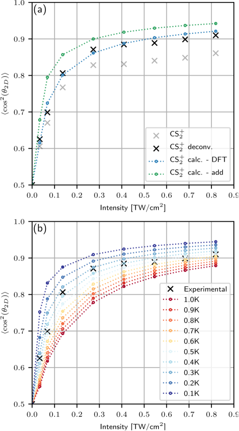
Figure 3 (a) shows the experimentally measured (crosses) and the simulated (circular markers and dashed line) degree of alignment () of the \ceCS2 dimer as a function of the alignment pulse intensity. The grey crosses represent the degree of alignment determined from the \ceCS2+ ion images without any correction for NAR, whereas the black crosses show the same measurements, corrected for NAR. The blue simulated trace was calculated using a polarizability anisotropy calculated using DFT assuming an inter-monomer separation of (such that ), whereas the green trace was calculated using a polarizability anistropy calculated by addition of the polarizability tensors of the two \ceCS2 monomers (such that ). Figure 3 (b) again shows the experimentally measured degree of alignment, corrected for NAR (crosses), together with the simulated degree of alignment calculated at a variety of different ensemble temperatures. For all the different ensemble temperatures, the polarizability anisotropy was chosen to be that which was calculated using DFT.
IV Discussion
Examining Figure 3 (a), several observations can be made. Firstly, it is clear that the observed degree of alignment rapidly increases as the alignment intensity is raised, before levelling out at higher intensities. Secondly, the deconvoluted data (black crosses) shows a higher degree of alignment than the data obtained directly from the ion images (grey crosses), as is expected due to the NAR in He droplets. Accordingly, the deconvoluted data is a better match to the simulated traces than the non-deconvoluted data. Additionally, the simulated trace that best matches the experimental data is the one employing a polarisability anistropy calculated by DFT methods, rather than that calculated via addition of the polarizability tensors of the two monomers.
The polarizability anisotropy calculated by DFT compared to the anisotropy calculated via addition of the polarizability tensors of the two monomers. This implies that there is some electronic (orbital) interaction between the two \ceCS2 units in the dimer, as the simple addition of polarizability elements neglects this. The electronic interaction lowers the overall polarizability anisotropy as the electron density in the region between the two \ceCS2 molecules is increased. This suggests that the interaction between the two \ceCS2 monomers has some orbital character - in addition to the expected (non-orbital) van der Waals interaction Hobza and Dethlefs-Müller (2010). The sensitivity to the polarizability anisotropy in this way illustrates the potential utility of laser-induced alignment as a diagnostic tool for studying non-covalent interactions and that it may be possible to gain some deeper insight into the electronic structure of such complexes with further study.
Turning to Figure 3 (b), it appears that the experimental data corresponds well to the simulated data using an ensemble temperature of between 0.3 and . This agreement implies that the alignment of the \ceCS2 dimers in the He droplets is well described by alignment of a ensemble of gas-phase \ceCS2 dimers. This is completely in line with the expected temperature of the dimers inside the He droplets Toennies and Vilesov (2004).
V Conclusion
We have shown that the C-C axis of \ceCS2 dimers embedded in He droplets can be tightly confined along the propagation direction of a circularly polarized laser pulse. The degree of this one-dimensional alignment was measured as a function of the intensity of the alignment pulse by Coulomb explosion imaging with an intense probe pulse. It was found that the measured degree of alignment, , as a function of intensity), matched well with calculated for a sample of \ceCS2 dimers with an adjusted rotational constant and a temperature of . As such, our results corroborate and generalize recent findings on \ceI_2 molecules in He droplets where the experimentally recorded degree of one-dimensional alignment, induced by a linearly polarized laser field, also agreed well with calculations of for a ensemble of \ceI_2 molecules with an adjusted rotational constant. Since molecules and complexes of molecules embedded in He droplets should, in general, thermalize to the environment we believe that the high degree of alignment enabled by the low temperature can be obtained for a wide variety of species. This will prove advantageous for applications that benefit from such rigorous control of the molecular frame, including diffractive imaging with (soft) x-rays Küpper et al. (2014); Gomez et al. (2014); Tanyag et al. (2015); Rupp et al. (2017), Coulomb explosion imaging Pickering et al. (2018b), and electron diffraction He et al. (2017); Zhang et al. (2014).
References
- Pentlehner et al. (2013a) D. Pentlehner, J. H. Nielsen, A. Slenczka, K. Mølmer, and H. Stapelfeldt, “Impulsive Laser Induced Alignment of Molecules Dissolved in Helium Nanodroplets,” Phys. Rev. Lett. 110, 093002 (2013a).
- Pentlehner et al. (2013b) D. Pentlehner, J. H. Nielsen, L. Christiansen, A. Slenczka, and H. Stapelfeldt, “Laser-induced adiabatic alignment of molecules dissolved in helium nanodroplets,” Phys. Rev. A 87, 063401 (2013b).
- Shepperson et al. (2017a) B. Shepperson, A. A. Søndergaard, L. Christiansen, J. Kaczmarczyk, R. E. Zillich, M. Lemeshko, and H. Stapelfeldt, “Laser-Induced Rotation of Iodine Molecules in Helium Nanodroplets: Revivals and Breaking Free,” Phys. Rev. Lett. 118, 203203 (2017a).
- Shepperson et al. (2017b) B. Shepperson, A. S. Chatterley, A. A. Søndergaard, L. Christiansen, M. Lemeshko, and H. Stapelfeldt, “Strongly aligned molecules inside helium droplets in the near-adiabatic regime,” J. Chem. Phys. 147, 013946 (2017b).
- Chatterley et al. (2017) A. S. Chatterley, B. Shepperson, and H. Stapelfeldt, “Three-Dimensional Molecular Alignment Inside Helium Nanodroplets,” Phys. Rev. Lett. 119, 073202 (2017).
- Shepperson et al. (2018) B. Shepperson, A. S. Chatterley, L. Christiansen, A. A. Søndergaard, and H. Stapelfeldt, “Observation of rotational revivals for iodine molecules in helium droplets using a near-adiabatic laser pulse,” Phys. Rev. A 97, 013427 (2018).
- Ramakrishna and Seideman (2005) S. Ramakrishna and T. Seideman, “Intense Laser Alignment in Dissipative Media as a Route to Solvent Dynamics,” Phys. Rev. Lett. 95, 113001 (2005).
- Vieillard et al. (2008) T. Vieillard, F. Chaussard, D. Sugny, B. Lavorel, and O. Faucher, “Field-free molecular alignment of CO2 mixtures in presence of collisional relaxation,” J. Raman Spectrosc. 39, 694–699 (2008).
- Lindgren and Kiljunen (2013) J. Lindgren and T. Kiljunen, “Excitation of rotons in parahydrogen crystals: The laser-induced-molecular-alignment mechanism,” Phys. Rev. A 88, 043420 (2013).
- Stickler et al. (2018) B. A. Stickler, B. Schrinski, and K. Hornberger, “Rotational Friction and Diffusion of Quantum Rotors,” Phys. Rev. Lett. 121, 040401 (2018).
- Schmidt and Lemeshko (2015) R. Schmidt and M. Lemeshko, “Rotation of Quantum Impurities in the Presence of a Many-Body Environment,” Phys. Rev. Lett. 114, 203001 (2015).
- Lemeshko (2017) M. Lemeshko, “Quasiparticle Approach to Molecules Interacting with Quantum Solvents,” Phys. Rev. Lett. 118, 095301 (2017).
- Toennies and Vilesov (2004) J. P. Toennies and A. F. Vilesov, “Superfluid Helium Droplets: A Uniquely Cold Nanomatrix for Molecules and Molecular Complexes,” Angew. Chem. Int. Ed. 43, 2622 (2004).
- Chatterley et al. (2018) A. S. Chatterley, C. Schouder, L. Christiansen, B. Shepperson, M. H. Rasmussen, and H. Stapelfeldt, “Long-lasting field-free alignment of large molecules inside helium nanodroplets,” ArXiv e-prints (2018), arXiv:1807.07376 .
- Meijer et al. (1990) G. Meijer, M. S. Vries, H. E. Hunziker, and H. R. Wendt, “Laser desorption jet-cooling of organic molecules,” Appl. Phys. B 51, 395–403 (1990).
- Choi et al. (2006) M. Y. Choi, G. E. Douberly, T. M. Falconer, W. K. Lewis, C. M. Lindsay, J. M. Merritt, P. L. Stiles, and R. E. Miller, “Infrared spectroscopy of helium nanodroplets: novel methods for physics and chemistry,” Int. Rev. Phys. Chem. 25, 15 (2006).
- Yang and Ellis (2012) S. Yang and A. M. Ellis, “Helium droplets: a chemistry perspective,” Chem. Soc. Rev. 42, 472 (2012).
- Pickering et al. (2018a) J. D. Pickering, B. Shepperson, L. Christiansen, and H. Stapelfeldt, “Femtosecond laser-induced coulomb explosion imaging of aligned OCS oligomers inside helium nanodroplets,” J. Chem. Phys. 149, 154306 (2018a).
- Pickering et al. (2018b) J. D. Pickering, B. Shepperson, B. A. K. Hübschmann, F. Thorning, and H. Stapelfeldt, “Alignment and imaging of the dimer inside helium nanodroplets,” Phys. Rev. Lett. 120, 1121321 (2018b).
- Stapelfeldt and Seideman (2003) H. Stapelfeldt and T. Seideman, “Colloquium: Aligning molecules with strong laser pulses,” Rev. Mod. Phys. 75, 543 (2003).
- Burt et al. (2018) M. Burt, K. Amini, J. W. L. Lee, L. Christiansen, R. R. Johansen, Y. Kobayashi, J. D. Pickering, C. Vallance, M. Brouard, and H. Stapelfeldt, “Communication: Gas-phase structural isomer identification by coulomb explosion of aligned molecules,” J. Chem. Phys 148, 091102 (2018).
- Smeenk and Corkum (2013) C. T. L. Smeenk and P. B. Corkum, “Molecular alignment using circularly polarized laser pulses,” J. Phys. B: At. Mol. Opt. Phys. 46, 201001 (2013).
- Moazzen-Ahmadi and McKellar (2013) N. Moazzen-Ahmadi and A. R. W. McKellar, “Spectroscopy of dimers, trimers and larger clusters of linear molecules,” Int. Rev. Phys. Chem. 32, 611 (2013).
- Rezaei et al. (2011) M. Rezaei, J. Norooz Oliaee, N. Moazzen-Ahmadi, and A. R. W. McKellar, “Spectroscopic observation and structure of CS2 dimer,” J. Chem. Phys. 134, 144306 (2011).
- Smeenk et al. (2014) C. T. L. Smeenk, L. Arissian, A. V. Sokolov, M. Spanner, K. F. Lee, A. Staudte, D. M. Villeneuve, and P. B. Corkum, “Alignment Dependent Enhancement of the Photoelectron Cutoff for Multiphoton Ionization of Molecules,” Phys. Rev. Lett. 112, 253001 (2014).
- Seideman and Hamilton (2005) T. Seideman and E. Hamilton, “Nonadiabatic Alignment by Intense Pulses. Concepts, Theory, and Directions,” Adv. At. Mol. Opt. Phys 52, 289–329 (2005).
- Fleischer et al. (2012) S. Fleischer, Y. Khodorkovsky, E. Gershnabel, Y. Prior, and I. S. Averbukh, “Molecular alignment induced by ultrashort laser pulses and its impact on molecular motion,” Isr. J. Chem. 52, 414–437 (2012).
- Larsen (2000) Jakob Juul Larsen, Laser Induced Alignment of Neutral Molecules, Ph.D. thesis, Aarhus University (2000).
- Søndergaard et al. (2017) A. A. Søndergaard, B. Shepperson, and H. Stapelfeldt, “Nonadiabatic laser-induced alignment of molecules: Reconstructing directly from by Fourier analysis,” J. Chem. Phys. 147, 013905 (2017).
- Friedrich and Herschbach (1995) B. Friedrich and D. Herschbach, “Alignment and trapping of molecules in intense laser fields,” Phys. Rev. Lett. 74, 4623–4626 (1995).
- Søndergaard (2016) A. A. Søndergaard, Understanding Laser-Induced Alignment and Rotation of Molecules Embedded in Helium Nanodroplets, Thesis, Aarhus University (2016).
- (32) R. Zillich, Private Communication.
- Seideman (2001) T. Seideman, “On the dynamics of rotationally broad, spatially aligned wave packets,” J. Chem. Phys. 115, 5965–5973 (2001).
- Hansen et al. (2012) J. L. Hansen, J. H. Nielsen, C. B. Madsen, A. T. Lindhardt, M. P Johansson, T. Skrydstrup, L. B. Madsen, and H. Stapelfeldt, “Control and femtosecond time-resolved imaging of torsion in a chiral molecule,” J. Chem. Phys. 136, 204310 (2012).
- Christensen et al. (2016) L. Christensen, L. Christiansen, B. Shepperson, and H. Stapelfeldt, “Deconvoluting nonaxial recoil in Coulomb explosion measurements of molecular axis alignment,” Phys. Rev. A 94, 023410 (2016).
- Hobza and Dethlefs-Müller (2010) P. Hobza and K. Dethlefs-Müller, Non-covalent Interactions, Theory and Experiment (RSC Publishing, 2010).
- Küpper et al. (2014) Jochen Küpper, Stephan Stern, Lotte Holmegaard, Frank Filsinger, Arnaud Rouzée, Artem Rudenko, Per Johnsson, Andrew V. Martin, Marcus Adolph, Andrew Aquila, Saša Bajt, Anton Barty, Christoph Bostedt, John Bozek, Carl Caleman, Ryan Coffee, Nicola Coppola, Tjark Delmas, Sascha Epp, Benjamin Erk, Lutz Foucar, Tais Gorkhover, Lars Gumprecht, Andreas Hartmann, Robert Hartmann, Günter Hauser, Peter Holl, Andre Hömke, Nils Kimmel, Faton Krasniqi, Kai-Uwe Kühnel, Jochen Maurer, Marc Messerschmidt, Robert Moshammer, Christian Reich, Benedikt Rudek, Robin Santra, Ilme Schlichting, Carlo Schmidt, Sebastian Schorb, Joachim Schulz, Heike Soltau, John C. H. Spence, Dmitri Starodub, Lothar Strüder, Jan Thøgersen, Marc J. J. Vrakking, Georg Weidenspointner, Thomas A. White, Cornelia Wunderer, Gerard Meijer, Joachim Ullrich, Henrik Stapelfeldt, Daniel Rolles, and Henry N. Chapman, “X-Ray Diffraction from Isolated and Strongly Aligned Gas-Phase Molecules with a Free-Electron Laser,” Phys. Rev. Lett. 112, 083002 (2014).
- Gomez et al. (2014) Luis F. Gomez, Ken R. Ferguson, James P. Cryan, Camila Bacellar, Rico Mayro P. Tanyag, Curtis Jones, Sebastian Schorb, Denis Anielski, Ali Belkacem, Charles Bernando, Rebecca Boll, John Bozek, Sebastian Carron, Gang Chen, Tjark Delmas, Lars Englert, Sascha W. Epp, Benjamin Erk, Lutz Foucar, Robert Hartmann, Alexander Hexemer, Martin Huth, Justin Kwok, Stephen R. Leone, Jonathan H. S. Ma, Filipe R. N. C. Maia, Erik Malmerberg, Stefano Marchesini, Daniel M. Neumark, Billy Poon, James Prell, Daniel Rolles, Benedikt Rudek, Artem Rudenko, Martin Seifrid, Katrin R. Siefermann, Felix P. Sturm, Michele Swiggers, Joachim Ullrich, Fabian Weise, Petrus Zwart, Christoph Bostedt, Oliver Gessner, and Andrey F. Vilesov, “Shapes and vorticities of superfluid helium nanodroplets,” Science 345, 906–909 (2014).
- Tanyag et al. (2015) Rico Mayro P. Tanyag, Charles Bernando, Curtis F. Jones, Camila Bacellar, Ken R. Ferguson, Denis Anielski, Rebecca Boll, Sebastian Carron, James P. Cryan, Lars Englert, Sascha W. Epp, Benjamin Erk, Lutz Foucar, Luis F. Gomez, Robert Hartmann, Daniel M. Neumark, Daniel Rolles, Benedikt Rudek, Artem Rudenko, Katrin R. Siefermann, Joachim Ullrich, Fabian Weise, Christoph Bostedt, Oliver Gessner, and Andrey F. Vilesov, “Communication: X-ray coherent diffractive imaging by immersion in nanodroplets,” Struc. Dyn. 2, 051102 (2015).
- Rupp et al. (2017) D. Rupp, N. Monserud, B. Langbehn, M. Sauppe, J. Zimmermann, Y. Ovcharenko, T. Möller, F. Frassetto, L. Poletto, A. Trabattoni, F. Calegari, M. Nisoli, K. Sander, C. Peltz, M. J. Vrakking, T. Fennel, and A. Rouzée, “Coherent diffractive imaging of single helium nanodroplets with a high harmonic generation source,” Nat. Comms. 8, 493 (2017).
- He et al. (2017) Y. He, J. Zhang, L. Lei, and W. Kong, “Self-assembly of iodine in superfluid helium droplets: Halogen bonds and nanocrystals,” Angw. Chem. 129, 3595–3599 (2017).
- Zhang et al. (2014) J. Zhang, Y. He, W. M. Freund, and W. Kong, “Electron Diffraction of Superfluid Helium Droplets,” J. Phys. Chem. Lett. 5, 1801–1805 (2014).