Transient rolling friction model for discrete element simulations of sphere assemblies
Abstract
The rolling resistance between a pair of contacting particles can be modeled with two mechanisms. The first mechanism, already widely addressed in the DEM literature, involves a contact moment between the particles. The second mechanism involves a reduction of the tangential contact force, but without a contact moment. This type of rotational resistance, termed creep-friction, is the subject of the paper. Within the creep-friction literature, the term “creep” does not mean a viscous mechanism, but rather connotes a slight slip that accompanies rolling. Two extremes of particle motions bound the range of creep-friction behaviors: a pure tangential translation is modeled as a Cattaneo-Mindlin interaction, whereas prolonged steady-state rolling corresponds to the traditional wheel-rail problem described by Carter, Poritsky, and others. DEM simulations, however, are dominated by the transient creep-friction rolling conditions that lie between these two extremes. A simplified model is proposed for the three-dimensional transient creep-friction rolling of two spheres. The model is an extension of the work of Dahlberg and Alfredsson, who studied the two-dimensional interactions of disks. The proposed model is applied to two different systems: a pair of spheres and a large dense assembly of spheres. Although creep-friction can reduce the tangential contact force that would otherwise be predicted with Cattaneo-Mindlin theory, a significant force reduction occurs only when the rate of rolling is much greater than the rate of translational sliding and only after a sustained period of rolling. When applied to the deviatoric loading of an assembly of spheres, the proposed creep-friction model has minimal effect on macroscopic strength or stiffness. At the micro-scale of individual contacts, creep-friction does have a modest influence on the incremental contact behavior, although the aggregate effect on the assembly’s behavior is minimal.
keywords:
Contact mechanics; granular materials; rolling; Hertz.Received Nov. 14, 2011; accepted after revision March 29, 2013
1 Introduction
In a Discrete Element (DEM) simulation of a granular material, each particle is represented as a discrete object that interacts with neighboring particles at its contacts. Each contact interaction yields the contact force that results from the movements of the two particles. Some recent DEM codes also include a possible contact moment that arises from the pair-wise rotational interactions of the particles. With this form of rotational resistance, the contact interaction is stiffened between the particle pairs, and the entire assembly is hardened and strengthened as a result. Besides imparting a macro-scale hardening, Iwashita and Oda [1] showed that contact moments also alter the internal length scale of an assembly, an effect that is evidenced by a change in the thickness and character of localization features such as shear bands. Ai et al. [2] provide a comprehensive survey of the many mechanisms that have been proposed for implementing a contact moment in DEM codes, mechanisms that include various combinations of rotational springs and rotational dissipation elements, such as rotational dampers and sliders. In the Paper, we consider an alternative form of rolling resistance and dissipation that does not involve contact moments. This mechanism, termed creep-friction, has its origins in the rolling friction literature and results from micro-slip at particle contacts. Within the creep-friction literature, the term “creep” does not mean a viscous mechanism, but rather connotes a gradual slip during rolling. Creep-friction has, as yet, received little attention within the DEM community. We begin by clarifying the distinction between two general forms of rotational resistance: contact moments and creep-friction. We then focus on the creep-friction mechanism of rotational resistance and describe its similarities and differences with translational resistance, in particular that of Cattaneo [3] and Mindlin [4], a type of sliding resistance that is widely used in DEM codes. Although, the creep-friction mechanism has received much interest over the past century, no exact solutions have been offered for many basic problems in two-dimensional interaction, let alone for the general three-dimensional conditions that one encounters in granular flows. The paper proposes an approximate model for creep-friction (Section 2) and then uses this model to gauge the relative importance of creep-friction in common granular phenomena (Section 3).
1.1 Two categories of rolling resistance
Two categories of rolling resistance can be distinguished by considering a pair of smooth cylindrical rollers of equal radius, one being driven by the other (Fig. 1).
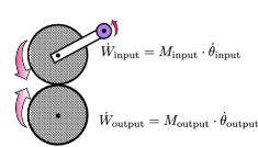
Various mechanisms can lead to energy dissipation, causing the input power to exceed the output power (here, and represent moments and rotational velocities). With the first category of rolling resistance, a contact moment acts between the two rollers so that the input moment exceeds the output moment, yet preserving the rotational velocities. This type of rolling resistance was used in the DEM simulations of Iwashita and Oda [1] and is now available in many DEM codes (see Ai et al. [2] for a survey). The presence of a contact moment is most obvious in the interaction of two gears that rotate with synchronous velocities, but in which the teeth rub in manner that causes a torque reduction between the two gears: a reduction that can be modeled as a contact moment. A contact moment is also produced when the two contacting materials are inelastic, which results in an asymmetry of stress within the small contact area between the two rolling objects. As rolling proceeds, the leading portion of the contact is continually loaded while the trailing portion is unloaded, and any difference in the loading and unloading stiffnesses (as a result of plasticity, viscosity, crushing, or sticky adhesion) will produce a small contact moment.
The second category of rolling resistance, also illustrated in Fig. 1, is the focus of the Paper. With this mechanism, the absence of a contact moment preserves the torque (that is, ), but the output rotational velocity is diminished between the driving roller and the driven roller. This latter type of resistance, termed creep-friction, results from micro-slip between the two rollers within their small contact region, causing energy dissipation in the absence of a contact moment. Both Reynolds [5] and Johnson [6] likened this type of micro-slip dissipation to the slip that occurs between a belt and its pulley. Creep-friction is the dominant dissipation mechanism in most rolling stock and, hence, received early attention in the investigation of rail-wheel interactions. As a train engine rolls steadily upon its rails, the wheel rim moves slightly faster than the train itself, and this small disparity increases as the grade steepens until, in the limit, the train stalls as the wheels spin futilely upon their rails. The paper concerns this form of rolling resistance and dissipation.
1.2 Creep-friction vs. Cattaneo-Mindlin sliding
Although both result from micro-slip within the contact zone, a distinction must be made between the mechanics of creep-friction rolling and that of translational sliding (see Figure 2 for a summary of these differences). The problem of translational interaction between two elastic spheres was independently solved by Cattaneo [3] and Mindlin [4], and this purely translational problem will be referred to as the Cattaneo-Mindlin problem. Its solution is in the form of a relationship between the translational (tangential) displacement and the tangential traction and force. This relationship is known to be complexly path-dependent, such that the tangential force depends upon the previous sequence of both tangential and normal displacements. Mindlin and Deresiewicz [7] developed solutions for eleven sequences of such loading and unloading, and these and other solutions of the translational problem have been widely incorporated into DEM codes (e.g., those of Thornton [8]; Lin and Ng [9]; Vu-Quoc and Zhang [10]; and Kuhn [11]).
The creep-friction mechanism was first recognized by Reynolds [5], but its investigation proceeded independently from that of the translational Cattaneo-Mindlin problem. The two-dimensional problem of creep-friction between two elastic rolling cylinders was solved by Carter [12] and Poritsky [13] in the form of an exact relationship between the tangential force and the ratio of the rotational velocities of the two cylinders. The three-dimensional problem of rolling between elastic spheres was later addressed in the thesis of Kalker [14], who developed an exact solution in the form of a series of elliptic functions. In subsequent work, Kalker developed solutions for a breadth of creep-friction problems, including solutions for a wider range of rotational velocities, solutions for different contact profiles, solutions for dissimilar bodies, and solutions for the simultaneous rolling and twisting (spin) of two bodies (see [15, 16] for compendiums of this work).
Figure 2 gives a cursory comparison of the Cattaneo-Mindlin and creep-friction problems and their associated mechanics.
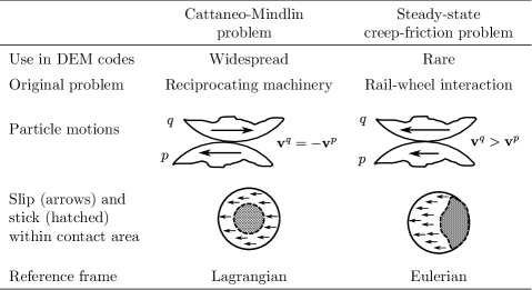
For both problems, the two contacting bodies are isotropically elastic but have a frictional limit that applies to tangential traction within the contact area. We assume that the two bodies are spheres of equal radius and possess identical elastic properties — the so-called quasi-identical condition in the creep-friction literature. For this situation, the two spheres touch within a small circular contact area, and the normal traction within this area is given by the Hertz solution, which applies to both the Cattaneo-Mindlin and creep-friction problems. In the translational Cattaneo-Mindlin problem, the two particles, labeled “” and “”, move in opposite directions with material velocities (Fig. 2, middle column). With creep-friction, the two velocities differ, perhaps only slightly, with one larger than the other, say . For the traditional problem of rail-wheel rolling interaction, this difference is very small (the wheel rim will typically move faster than the train by only a fraction of a percent), but solutions have also been developed for a wide range of velocity differences (see Kalker [16]). A difference in the two velocities produces an asymmetric condition across the contact area, in the sense that material from each body will enter the contact along one edge of the contact area and will exit the contact along the opposite edge. This situation produces an asymmetric slip area within the contact: slip occurs near the exit (trailing) edge, whereas stick (no slip) occurs near the entering (leading) edge (see Fig. 2, right column). The situation is different from the Cattaneo-Mindlin problem, in which slip occurs within a symmetric annular area that surrounds an inner circular stick region. Because material continually enters and leaves the contact zone, the rolling creep-friction problem is usually formulated within the context of a moving frame using Eulerian kinematics; whereas, the Cattaneo-Mindlin problem is usually solved within a stationary frame using Lagrangian kinematics. The Eulerian approach is described in the following section.
2 Model formulation
2.1 Contact kinematics
Material points and are at the centers of two smooth particles, and , and these points have positions and within the global reference frame (Fig. 3).

For the moment, we will assume that the particles are rigid and that the contact is an infinitesimal point. Vectors and connect the material points and to the contact point. Between the times and , the particles undergo incremental translation and rotation movements , , , and , and these four movement vectors are described by their twelve scalar components, forming a 12-dimensional vector space of possible movements. Through a suitable transformation of these twelve components, we can identify six relative movements that are objective, in the sense that equivalent movements would be reported by two observers having independent motions [17, 18]. The remaining six movements are, in essence, observer-dependent rigid-body motions that are non-objective. The six objective, relative movements include three translational movements (which we collect in a “relative displacement vector,” ) and three rotational movements. The relative displacement is
| (1) |
representing the translation of a point attached to at the contact relative to its counterpart on particle , again assuming that the two particles are rigid.
The three remaining objective movements are associated with relative rotations. Two of these three movements comprise a rolling displacement vector , which represents the average of the movements of two material points — one attached to particle near the contact and the other attached to — between the times and . Because the instantaneous motions of two rigid bodies lie within the tangent plane at their contact, the 3-vector has only two independent components. Kuhn and Bagi [19] have shown that this rolling vector is objective and that it can be computed from the incremental motions of two smooth rigid particles of arbitrary smooth shape, as
| (2) |
where and are the curvature tensors of the two surfaces; is the unit normal vector of the tangent plane (directed outward from particle ); and the tangential displacement is the projection of onto the tangent plane:
| (3) |
| (4) |
in which is the normal displacement. We adopt a direction of that is consistent with the creep-rolling literature: the direction of material passing through the contact area. Equation (2) is greatly simplified when the two surfaces are spherical at the contact:
| (5) |
where and are the convex surface radii of the two particles at the contact. Both and are 3-vectors that lie in the tangent plane, each with two independent components.
The third rotational movement is a twisting (torsion, spin) of one particle relative to the other, taken about the normal vector . Although such twisting can alter the distribution of traction within the contact area (and, hence, has received considerable attention within the creep-friction literature), it will not be considered in the Paper, which is confined to the effects of contact displacement and rolling, and .
The kinematics, thus far, have been limited to rigid particles. If the particles were truly rigid, the contact would be a single point; the relative displacement would not include any normal component that would violate the particles’ impenetrability (a constraint ); and any tangential component would produce full frictional sliding between the particles. We now remove the rigidity constraint and permit the particles to deform. These particle deformations will enable contact across a finite area; will give rise to a Hertzian normal traction within this contact area; and will inhibit tangential slip, allowing the particles to stick within portions of the contact area. The tangential displacement fields produced by the two particles’ deformations are designated and , and these displacement fields will vary across the contact area between the two particles. The difference
will tend to reduce the slip that otherwise would be produced by the rigid translational displacement . Indeed, no slip will occur within those portions of the contact area where the vector field fully counteracts the tangential displacement vector .
In general, as the particles move and roll, the contact area will move across the surfaces of the two particles at the rate . By adopting an Eulerian frame that moves with the contact, the vector field of tangential slip within the contact area, , is
| (6) |
For the non-sliding (stick) portions of the contact area, , but is non-zero elsewhere within the slip portion of the contact area. The final term in Eq. (6) represents a “convection of tangential displacement” into the contact area, as material is moved (in effect, rolled) through the area. The gradient tensors represent planar deformations (stretching and shearing) of the two particles within the contact plane. Equation (6) is widely used within the creep-friction literature, although usually in a scalar form [6, 15, 16]. In keeping with convention, the displacement is written as a derivative within the moving frame to emphasize its transient nature, as will be discussed below. Although and are vector fields across the contact region and the are tensor fields across the contact region, both and are merely 3-vectors that result from the incremental particle motions. These vectors can be readily computed within each time step of a DEM algorithm, with Eqs. (1)–(5).
2.2 Creep-friction and Cattaneo-Mindlin solutions
The fundamental aim of elastic contact mechanics is finding the deformations, stresses, and tractions as solutions to a problem of three-dimensional elasticity. In this problem, Eq. (6) serves as a displacement boundary condition across the surface of a single particle body within its contact area. The remaining boundary conditions include a requirement of zero traction outside of the contact area; a requirement that the tangential traction does not exceed the friction limit within those non-sliding portions of the contact area (wherever ); a requirement that for those portions in which the friction limit is exceed, the direction of is aligned with the tangential traction; and a requirement that the normal displacements of the two particles comply within the contact area.
In the Cattaneo-Mindlin problem, two particles are assumed to move in opposite directions at their contact, with , thus leaving only the first and second terms on the right of the boundary condition (6) (see the middle column of Fig. 2). On the other hand, the classic problem in creep-friction assumes that rolling has attained a steady-state condition in which the second term vanishes, leaving only the first and third terms on the right of Eq. (6). The steady-state condition would apply to a train moving at constant speed: to an observer who moves with the rail-wheel contact, the rail and wheel appear to pass through a stationary contact zone, and deformations within the rail and wheel appear to be constant within the moving frame, with . The situation in DEM simulations is far more complex than either of these extreme cases, since particles will both roll and slide in bewildering sequences that produce loading and unloading in both normal and tangential directions, all within a three-dimensional setting. The term transient conditions is used within the creep-friction literature for cases in which all three terms are active within the boundary condition given by Eq. (6). Only the simplest of these transient conditions have been addressed in the literature.
In a later section, an approximate solution of the transient problem will be proposed for the contact of two spheres. This approximation is an amalgam of separate solutions of the Cattaneo-Mindlin problem and of the steady-state creep-friction problem. As for the former, the Cattaneo-Mindlin problem has been largely solved in the works of Cattaneo, Mindlin, Deresiewicz, and others [3, 4, 7, 10, 20, 11], and these solutions have been widely incorporated in DEM codes. Omitting the details, solutions of the Cattaneo-Mindlin problem can be represented as
| (7) |
in which is the 3-vector incremental change in the tangential contact force that corresponds to a given tangential displacement increment (in conventional DEM codes, and are assumed equal, an assumption that does not apply to transient creep-friction). The symbol represents a tangential compliance function based upon Cattaneo-Mindlin (C-M) theory, and its inverse is the corresponding tangential contact stiffness function. In the context of a DEM code, represents an algorithm (function, subroutine, procedure, etc.) that computes an output from an input . This compliance function will depend upon the elastic coefficients, the friction coefficient, the normal force, the concurrent normal displacement (), and the contact’s loading history.
As for the steady-state creep-friction problem, approximate solutions for elastic spheres were developed in the 1960’s by Haines and Ollerton [21] and by Vermeulen and Johnson [22]. Although not a closed-form solution, Kalker [14] derived an exact solution in the form of a series of elliptic functions and also developed software for implementing this solution [23]. With the steady-state problem, rolling proceeds steadily in one direction, and the various creep-friction solutions all have the general scalar form
| (8) |
where is termed the steady-state creepage and is the corresponding creepage function. During steady-state creep-friction, the velocity (or the corresponding increment ) represents a continual slipping of the contact as it rolls at rate (or with the corresponding increment ). For the traditional wheel-rail problem, the ratio of the displacement (slipping) and rolling velocities is usually small, often less than one percent. The creepage function depends upon the elastic coefficients, the normal force , the friction coefficient , and the ratio of the tangential force to the limiting force (the product of and ). The creepage function increases monotonically with the ratio . As in the previous analogy, the tractive force will increase when a locomotive engine moves up a steepening grade, causing the micro-slip creepage to increase as well.
Both Carter [12] and Poritsky [13] developed exact solutions for the creepage function of the two-dimensional cylinder-cylinder problem, which has served as a basis for wheel-rail rolling. Kalker [16] developed the following approximation of the creepage function for the three-dimensional sphere-sphere problem:
| (9) |
in which is the shear modulus, is the radius of the contact area, and is a coefficient that depends upon the Poisson ratio (Table 1).
| Poison ratio | Kalker coefficient |
|---|---|
| 0 | 3.40 |
| 0.25 | 4.12 |
| 0.50 | 5.20 |
Kalker’s creepage function was shown to be exact for small creepage rates (a situation termed linear creep, corresponding to small values of ), and it also correctly predicts gross sliding at the friction limit (that is, as ). For intermediate values of , Kalker [23] showed that Eq. 9 closely fits the experimental data of Johnson [6].
With Hertzian contact, the , , and are inter-related, as , and Kalker’s Eq. (9) can be expressed in the alternative form,
| (10) |
where is the particle radius and is the Poisson ratio. This form is instructive, as it shows that the creepage is non-dimensional and depends directly upon the ratio of the contact and particle radii, , a matter that will be discussed in the Section sec:implementation.
2.3 Proposed contact model
Although exact solutions have been developed for the two extremes of pure Cattaneo-Mindlin sliding and pure steady-state creep-friction, the situation is far less accomplished for the intermediate, transient conditions that are likely to predominate in DEM simulations of granular flow. Kalker [24, 25] developed exact solutions for several transient cases involving cylinders. In one case, two stationary cylinders, initially sustaining a pure translational force , then begin to roll while maintaining constant and (appropriately, the sequence is termed “Cattaneo-to-Carter”). Kalker found that the transition in traction from pure Cattaneo-Mindlin sliding to pure steady-state creep friction was complete when the two cylinders had rolled a distance , twice the radius of the contact area. Kalker [26] later developed an approximate approach for analyzing transient conditions, modeling the contact area as a Winkler bed of tangential springs (the so-called “brush model”). This approach was used by Al-Bender and De Moerlooze [27] to analyze the case of two spheres, initially pressed together with normal force but zero tangential force, that are then rolled, with each particle rotating at a constant rate, one particle slightly faster than the other, to maintain a constant creepage ratio . Full slip was found to occur when the accumulated tangential displacement equaled the radius of the contact area, .
In a recent paper, Dahlberg and Alfredsson [28] further simplified the brush approach for the transient rolling of two cylinders. They reformulated Eq. (6) by setting the slip , as would apply within the stick portion of the contact area, and by approximating the remaining terms as
In this scalar form, the deformation field in the second term of Eq. (6) is approximated with a scalar version of Eq. (7) using a linear compliance for the function . The final, convection term in Eq. (6) is approximated as the steady-state creepage function multiplied by the rolling increment (the exact Carter [12] creep function was used in this two-dimensional analysis of cylinder rolling). With these approximations, the increment of tangential force is computed as
| (11) |
This form is well suited for displacement driven computations, such as those in DEM codes, in which the contact force must be calculated from the rolling and sliding displacements within each time step.
Dahlberg and Alfredsson [28] validated their approximation by comparing it with results of a finite element (FEM) model of two identical elastic cylinders. Besides confirming that their model closely approximates Kalker’s Cattaneo-to-Carter solution, they also modeled the problem of two cylinders that are initially pressed together with force and are then rolled with a constant creepage ratio . Figure 4
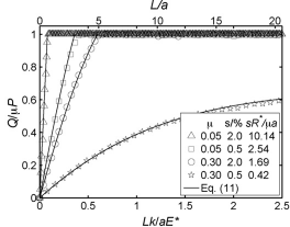
is adopted from their paper and shows the results from both Eq. (11) and from their FEM model. The cumulative rolling distance is normalized by dividing by the contact radius, . The results are for two creepage ratios and for two friction coefficients , as shown. For large creepage ratios and small friction coefficients, nearly full slip develops (with tangential force close to ) at rolling distances of less than . With a small creepage ratio and large friction coefficient, the eventual approaches a reduced condition that applies to steady-state creep-friction, but only after undergoing large rolling displacements.
An approximate three-dimensional contact model is now developed by adapting the approach of Dahlberg and Alfredsson to sphere-sphere contacts. The first term on the right of Eq. (6), , is the 3-vector of rigid-body tangential displacement, as computed with Eqs. (1) and (4). We approximate the second term on the right of Eq. (6) as the tangential deformation that would result from a force increment if the contact were undergoing a pure sliding motion: the deformation computed with the Cattaneo-Mindlin compliance function (shown symbolically in Eq. 7). The final term in Eq. (6) is approximated as the creepage displacement that would result from a rolling increment if the contact were undergoing pure steady-state creep-friction. In a three-dimensional setting, the scalar creepage is assumed to take the tensor form
| (12) |
such that
| (13) |
where is the incremental rolling vector computed with Eq. (2) or (5). The creep function gives the scalar magnitude of creep displacement, whereas the dyad carries information about the unit direction of the creep displacement and the unit direction upon which is projected. That is, tensor is a rank-1 linear transformation from the rolling increment to the creep displacement. We further assume that creepage proceeds in the direction of the shearing force , such that
| (14) |
and that the creepage displacement is prodded by the full magnitude of the rolling increment, such that
| (15) |
Following the approach of Dahlberg and Alfredsson, we set in Eq. (6) and substitute Eqs. (7) and (12)–(15), with the resulting approximation
| (16) |
where Kalker’s creepage function, , is used for the rolling of two identical spheres (see Eqs. 9 and 10).
Although Eq. (16) is merely an approximate solution of a complex three-dimensional boundary-value problem, it does match exact solutions in two respects. After an extended absence of rolling , the equation gives the exact Cattaneo-Mindlin result for sliding displacements (Eq. 7). Moreover, after an extended period of constant creepage, , the equation gives the exact steady-state creep-friction result (Eqs. 8 and 10). That is, Eq. (16) fits the two extremes of pure Cattaneo-Mindlin sliding and pure steady-state creep-friction.
The creep friction model of Eq. (16) differs from contact models that incorporate rotational springs and sliders. Whereas rotational springs will stiffen the contact behavior, creep-friction softens the contact resistance, as a rolling term is subtracted from the translational displacement , reducing the force increment . Although this softening might seem a type of viscosity, the effect of creep-friction depends upon a dimensionless ratio of two objective rates — the displacement and rolling rates — as is apparent in Eqs. (8) and (16). This creep-friction model is, therefore, rate-independent and objective.
Equation (16) also suggests the relative importance of translational and rolling movements in affecting the contact force . Unlike , the rolling movement is multiplied by the ratio of the contact and particle radii, , which will usually be much smaller than 1. For example, with a quartz sand or other geologic material confined at 1 atmosphere of pressure, the ratio is less than 2%, and the tangential force will be influenced much less by the rolling velocity than by the sliding velocity. The effect of rolling will be much larger, of course, with softer materials confined at larger pressures.
When used in DEM simulations, the Eq. (16) has a number of attractive features:
- 1.
-
2.
The equation models arbitrary combinations of sliding and rolling. Moreover, it allows an arbitrary concurrent normal displacement and normal force . The three increments — , , and — can be expected to occur in almost any combination and in almost any sequence during a DEM simulation.
-
3.
The stiffness function would already exist as a procedure or subroutine within an existing DEM code, receiving the full tangential displacement as input and returning as its output. Eq. (16) can utilize an existing code for and only requires an amendment of the input .
Vu-Quoc and Zhang [10] proposed a model for rolling contact that has some similarities with Eq. (16). Using a different approach, they arrived at a scalar equation for an effective displacement that would be used to compute the force increment :
where is the cumulative tangential displacement. The proposed equation (16) has the advantage of conforming with established theory when two spheres undergo pure steady-state creep-friction rolling.
3 Implementation
In this section, we investigate creep-friction and rolling in two granular systems: (1) a two-particle system that undergoes a simple combination of sliding and rolling, and (2) a system of 4096 densely packed spheres loaded in triaxial compression. The purpose is to establish the relative importance of creep-friction in the behavior of the two systems.
3.1 Two-particle system
In the first system, two equal-radius spheres are pressed together so that the indentation of each particle, , is 0.01% of its radius (in DEM parlance, the indentation is half of the overlap). In this initial state, no tangential force is applied, and the contact radius “” is 1% of (with Hertz contact, the contact radius equals ). While maintaining a constant indentation and a constant normal force , the two spheres are then rotated in opposite directions, one faster than the other, creating both rolling and tangential displacements in small increments and . A constant creep ratio is maintained during this process. The progressively increasing tangential displacement causes the tangential force to increase from its initial, zero condition to an eventual value that is equal to or less than the friction limit . Figure 5 shows the advancing tangential force for several different inverse creep ratios .


The tangential force has been normalized with respect to the friction threshold . Figure 5a shows the increasing tangential force versus the cumulative displacement (), where the displacement has been normalized with respect to the indentation . Fig. 5b also shows the same tangential force, but plotted against the cumulative rolling distance , where the rolling distance has been normalized with respect to the contact radius “”. The two different ways of normalizing displacement are consistent with the two limits of contact behavior. In the extreme of sliding with no rolling (), the tangential stiffness only depends upon the normal indentation and the parameters and (see §2 of [7]). At the other extreme, predominated by rolling (), the steady-state tangential force depends upon the contact radius “” (as in Eq. 10).
Figure 5a shows that the rolling rate has negligible effect upon the tangential force unless the rolling rate is much larger than the displacement rate, with an inverse ratio larger than 10. That is, the eventual tangential force can be greatly reduced from the friction limit , but a significant reduction will only occur when the rolling rate is much larger than the displacement rate. Figure 5b shows that a reduction in the eventual tangential force is only realized after a long and sustained cumulative rolling motion: only after the two particles have rolled across each other a distance of several contact radii “”. Such vigorous and sustained rolling is unlikely to occur during brief collisional encounters between particles, as might occur in the collisions of a rapidly sheared granular gas. The effect of rolling creep-friction might be more significant, however, during slow, sustained motions, as would occur in dense granular flows, where contacts persist for longer periods of gross deformation. This possibility is investigated in a second application of the creep-friction model.
3.2 Triaxial compression of 4096-particle system
In the second system, two assemblies of 4096 densely packed spheres are slowly loaded in triaxial compression. Because the creep-friction equation (16) suggests that the effect of rolling depends upon the ratio , the two assemblies differ in the radii of their contact areas relative to the particle radius. The first assembly has relatively small contacts (small ratios ), as it contains relatively hard particles that are confined at a lower pressure. The second assembly contains softer particles and is confined at a higher pressure, so that the contacts are larger (large ratios ).
Both assemblies contain the same 4096 spheres, ranging in size from 0.4 to 1.5, where is the median diameter. The particles are tightly packed into a cube container having periodic boundaries on all sides. Starting with this same initial arrangement of spheres, the two assemblies were allowed to adjust to the particular elastic properties of their particles and their confining stress, yet producing about the same bulk density (see Table 2).
| Values | ||
| Smaller | Larger | |
| Characteristic | contacts | contacts |
| Particles | 4096 | |
| Particle shape | Spheres | |
| Particle shear modulus, | 29 GPa | 1.2 GPa |
| Particle Poisson ratio, | 0.15 | 0.34 |
| Friction ratio, | 0.50 | 0.50 |
| Confining pressure, | 10 kPa | 1800 kPa |
| Initial indentation, | 0.0054% | 1% |
| Initial contact radius, | 0.73% | 10% |
| Initial void ratio | 0.513 | 0.461 |
| Initial avg. coordination no. | 1.86 | 2.46 |
Particles in the first assembly are assigned the elastic properties of quartz, and this assembly was initially confined with a mean stress of 10kPa (for a sand, this pressure would be attained at a burial of about 0.5m). Under these conditions, the average contact indentation is about 0.0054% of the mean particle radius , and the average contact radius is about 0.73% of the particle radius (Table 2). Particles in the second assembly are given the softer properties of a polymeric plastic and are confined to the higher mean stress of 1.8MPa, so that the average contact indentation is about 1% of the mean particle radius, and the mean contact radius is about 10% of the particle radius. Following the initial isotropic compaction, a deviatoric loading is applied in the form of triaxial compression: compressing the assembly in one direction at a constant rate of strain while the assembly is allowed to expand equally in the other two directions so that a constant mean stress is maintained within the assembly. With each assembly, two simulations are run. In one simulation, the effect of creep-friction is included, by using Eq. (16) to compute the tangential contact force. With the second simulation, creep-friction is negated by using a standard Cattaneo-Mindlin model of tangential force: . In both contact models, the Jäger algorithm was used to implement the stiffness function [11].
The results of four simulations are shown in Fig. 6: for assemblies with small and with large contacts, and for simulations with and without creep-friction.


Although different line styles are used for plotting the two contact models, the results are almost indistinguishable: the inclusion of creep-friction in the contact model has almost no discernible effect on the macro-scale behavior of either assembly.
We now consider the micro-scale behavior in three respects: (1) a comparison of the relative amounts of rolling for the two assemblies (assemblies with small and large contacts), (2) a comparison of the relative amounts of rolling for the contact models with and without creep-friction, and (3) the effect of creep-friction on the incremental contact response.
Table 3 compares the relative amounts of rolling among the contacts of the two assemblies.
| Quartiles | |||||
| Assembly | Contact model | Mean | 1st | Median | 3rd |
| Small contacts | Cattaneo-Mindlin | 40 | 3.5 | 18 | 43 |
| Creep-friction, Eq. (16) | 43 | 3.2 | 20 | 49 | |
| Large contacts | Cattaneo-Mindlin | 8.5 | 1.2 | 3.7 | 8.5 |
| Creep-friction, Eq. (16) | 8.7 | 1.2 | 4.4 | 9.8 | |
The statistics are taken from snapshots at a compressive strain of 23% (see Fig. 6). The table gives the ratios of the rolling rates to the rates of translational displacements among the 10,000 contacts at this strain. Values are given for the two assemblies, each with the two contact models: the standard Cattaneo-Mindlin contact model (without a creep-friction rolling effect) and the transient creep-friction model of Eq. (16). Two trends are apparent in Table 3:
-
1.
The assembly with the larger contacts (i.e., larger ratio of contact radius to particle radius, , due to its softer particles and larger confining stress) exhibits less rolling than the assembly with smaller contacts. That is, the ratios are larger for the assembly with the smaller contacts. This result, perhaps unexpected, is discussed below.
-
2.
The inclusion of creep-friction is seen to reduce the amount of rolling at the contacts — but only slightly. This small, nearly indistinguishable change at the micro-scale is consistent with the nearly identical macro-behavior shown in Fig. 6.
With the first trend, the amount of rolling is shown to depend upon the relative size of the contacts. This trend is found by comparing the results from assemblies with small and large contacts, since the average ratio differs by a factor of more than 13 for these two assemblies. In one sense, the difference in rolling rates is unexpected, as neither contact model includes any contact moments that would overtly inhibit rolling within the assembly having the larger contacts. Moreover, the inclusion of creep-friction in the contact model has a minimal effect upon the rolling rates, as noted in the second trend. Although unexpected, the more vigorous micro-scale rolling for small confining pressures (i.e., small contacts) is likely related to certain macro-scale behaviors in granular materials. The pressure-dependent strength of granular materials is a signature characteristic of their mechanical behavior: the strength of a granular material increases with the confining pressure. Strength is not always proportional, however, to the confining pressure, an observation that is usually attributed to the more vigorous dilation that occurs at low pressures. The dependence of the rolling rates upon the contact size (and, hence, on the confining pressure) suggests a type of micro-scale behavior that controls the rate of dilation. When two particles roll, their motions conform to the curvatures of the two surfaces (Eq. 2) and their indentations (or overlaps) are preserved; but when particles slide, the original points of contact on the two surfaces are offset. That is, the two forms of interaction — rolling and sliding — likely produce different volumetric responses.
The relative effect of creep-friction on the micro-scale behavior is explored with Table 4, which gives statistics among the 10,000 contacts at a strain of 23%.
| Relative effect of creep-friction, Eq. 17 | ||||
| Quartiles | ||||
| Assembly | Mean | 1st | Median | 3rd |
| Small contacts | 0.10 | 0.009 | 0.04 | 0.11 |
| Large contacts | 0.30 | 0.049 | 0.14 | 0.34 |
The transient creep-friction model of Eq. (16) was used in assemblies having small and large contacts. In the equation, the stiffness function is applied to a contact displacement that has been altered by the concurrent rolling increment . The relative extent of this alteration, therefore, serves as a measure of the relative effect of creep-friction on individual contacts. Table 4 presents statistics of the alteration relative to the magnitude of the displacement itself, in the form of the ratio
| (17) |
Two trends are apparent in Table 4:
-
1.
Although rolling proceeds vigorously in both assemblies, the relative effect of creep-friction is modest. For example, the previous Table 3 shows that the mean rate of rolling is about 40 times the rate of displacement for the assembly with smaller contacts. yet the relative effect of creep-friction has a mean value of only 0.10 (Table 4). This small effect is due to a relative contact size, the ratio , that is much less than one (Eqs. 16 and 17).
-
2.
Creep-friction has a greater influence on incremental behavior in the assembly with larger contacts. Even though rolling is less vigorous among larger contacts, the larger ratio enhances its influence.
Although the incremental effect of creep-friction is shown to be modest in Table 4, the influence is certainly not small. One might expect that creep-friction would have a modest effect on the macro-scale stress-strain behavior, but instead, the influence of creep-friction is shown to be altogether insignificant in Fig. 6. This contradictory result is attributed to three reasons. First, the effect of rolling on the tangential force will be minimal unless the relative rate of rolling (i.e., the inverse creepage ) is greater than 10 or more, as is shown in Fig. 5a. Second, even when the rolling rate is large, this rolling must be sustained for long periods (i.e., rolling distances) in order to significantly reduce the friction limit (see Fig. 5b). The inter-particle motions within a dense assembly are fairly erratic, in that contact motions frequently change direction over rather small periods of strain (e.g., §1 of [11]), not allowing the sustained, uniform motions that are necessary for rolling to have a significant effect on the contact forces. Finally, numerous studies have shown that the bulk strength of a granular material is insensitive to the friction coefficient , since strength results primarily from an anisotropy of the normal contact forces (e.g., [29]). That is, any small influence of creep-friction upon the contact tangential forces will have an even smaller effect upon the material’s bulk strength.
4 Conclusions
The paper identifies two categories of rotational resistance and dissipation between contacting bodies: one category results in a contact moment, the other results in micro-slip. Until now, only the first category has been applied in DEM simulations through the use of rotational springs, dampers, and sliders. The latter form of rotational resistance — termed creep-friction — is investigated in the paper. This mechanism complements the pure translational sliding of a Cattaneo-Mindlin mechanism, a mechanism that is widely implemented in DEM codes. Although exact solutions are available for pure, steady-state creep-friction and for pure Cattaneo-Mindlin sliding, DEM simulations require solution of the more complex, transitional behavior between these two extremes (an intermediate condition called the “transient problem” in the rolling friction literature). An approximate solution to the three-dimensional transient problem is proposed. The solution is consistent with both extremes of pure creep-friction and pure Cattaneo-Mindlin sliding, and it is also consistent with a two-dimensional solution that has been verified with elastic analysis.
When applied to a system of two spheres, creep-friction is shown to be significant only when the particle motions are dominated by rolling, when translational sliding is minimal, and when such motions are sustained for long rolling distances while the particles remain in persistent contact. DEM simulations with sphere assemblies demonstrate that the creep-friction mechanism has a modest effect on the micro-scale behavior but an almost imperceptible effect on the observed macro-scale behavior. These results are reassuring, as the creep-friction mechanism has been overlooked during the past several decades in which DEM has been used for investigating granular behavior.
Acknowledgements
This material is based upon work supported by the National Science Foundation under Grant No. NEESR-936408.
References
- [1] K. Iwashita, M. Oda, Rolling resistance at contacts in simulation of shear band development by DEM, J. Engrg. Mech. 124 (3) (1998) 285–292.
- [2] J. Ai, J.-F. Chen, J. M. Rotter, J. Y. Ooi, Assessment of rolling resistance models in discrete element simulations, Powder Tech. 206 (3) (2011) 269–282.
- [3] C. Cattaneo, Sul contatto di due corpi elasticiti, Accademia dei Lincei, Rendiconti, Series 6 27 (1938) 342–348.
- [4] R. D. Mindlin, Compliance of elastic bodies in contact, J. Appl. Mech. 16 (1949) 259–268.
- [5] O. Reynolds, On rolling-friction, Phil. Trans. Roy. Soc. Lond. A 166 (1876) 155–174.
- [6] K. L. Johnson, Contact Mechanics, Cambridge Univ. Press, 1985.
- [7] R. Mindlin, H. Deresiewicz, Elastic spheres in contact under varying oblique forces, J. Appl. Mech. 19 (1) (1953) 327–344.
- [8] C. Thornton, C. W. Randall, Applications of theoretical contact mechanics to solid particle system simulation, in: M. Satake, J. Jenkins (Eds.), Micromechanics of Granular Materials, Elsevier Science Pub. B.V., Amsterdam, The Netherlands, 1988, pp. 133–142.
- [9] X. Lin, T.-T. Ng, A three-dimensional discrete element model using arrays of ellipsoids, Géotechnique 47 (2) (1997) 319–329.
- [10] L. Vu-Quoc, X. Zhang, An accurate and efficient tangential force-displacement model of elastic frictional contact in particle-flow simulations, Mech. of Materials 31 (4) (1999) 235–269.
- [11] M. R. Kuhn, Implementation of the Jäger contact model for discrete element simulations, Int. J. Numer. Methods Engrg. 88 (1) (2011) 66–82.
- [12] F. W. Carter, On the action of a locomotive driving wheels, Proc. R. Soc. Lond. A 112 (1926) 151–157.
- [13] H. Poritsky, Stresses and deflections of cylindrical bodies in contact with application to contact of gears and of locomotive wheels, J. Appl. Mech. 17 (1950) 191–201.
- [14] J. J. Kalker, On the Rolling Contact of Two Elastic Bodies in the Presence of Dry Friction, Nederlandsch Drukkerij Bedrijf N. V., Leiden, 1967, thesis Delft.
- [15] J. J. Kalker, Three-dimensional elastic bodies in rolling contact, Kluwer Acad. Publ., Dordrecht, The Netherlands, 1990.
- [16] J. J. Kalker, Rolling contact phenomena — linear elasticity, in: B. Jacobson, J. J. Kalker (Eds.), Rolling Contact Phenomena, No. 411 in Courses and Lectures, CISM, Springer, Wien, 2000, pp. 1–84.
- [17] M. R. Kuhn, K. Bagi, Contact rolling and deformation in granular media, Int. J. Solids Structures 41 (21) (2004) 5793–5820.
- [18] M. R. Kuhn, K. Bagi, On the relative motions of two rigid bodies at a compliant contact: application to granular media., Mech. Research Comm. 32 (4) (2005) 463–480.
- [19] M. R. Kuhn, K. Bagi, Alternative definition of particle rolling in a granular assembly, J. Engrg. Mech. 130 (7) (2004) 826–835.
- [20] J. Jäger, New Solutions in Contact Mechanics, WIT Press, Southampton, UK, 2005.
- [21] D. J. Haines, E. Ollerton, Contact stress distributions on elliptical contact surfaces subjected to radial and tangential forces, Proc. Inst. of Mech. Engrs. 177 (4) (1963) 95–114.
- [22] P. J. Vermeulen, K. L. Johnson, Contact of nonspherical elastic bodies transmitting tangential forces, J. Appl. Mech. 31 (1964) 338–340.
- [23] J. J. Kalker, A fast algorithm for the simplified theory of rolling contact, Vehicle System Dynamics 11 (1982) 1–13.
- [24] J. J. Kalker, A minimum principle for the law of dry friction, with application to elastic cylinders in rolling contact—part 1: Fundamentals—application to steady rolling, J. Appl. Mech. 38 (4) (1971) 875–880.
- [25] J. J. Kalker, A minimum principle for the law of dry friction, with application to elastic cylinders in rolling contact—part 2: Application to nonsteadily rolling elastic cylinders, J. Appl. Mech. 38 (4) (1971) 881–887.
- [26] J. J. Kalker, Simplified theory of rolling contact, Tech. Rep. 1, Delft Progress Report, Series C (1973).
- [27] F. Al-Bender, K. De Moerlooze, A model of the transient behavior of tractive rolling contacts, Advances in Tribology 2008 (2008) 214894.
- [28] J. Dahlberg, B. Alfredsson, Transient rolling of cylindrical contacts with constant and linearly increasing applied slip, Wear 266 (1-2) (2009) 316–326.
- [29] C. Thornton, Numerical simulations of deviatoric shear deformation of granular media, Géotechnique 50 (1) (2000) 43–53.