Jetting to dripping transition: critical aspect ratio in step emulsifiers
Abstract
Fully three-dimensional, time-dependent, direct simulations of the non-ideal Navier-Stokes equations for a two-component fluid, shed light into the mechanism which inhibits droplet breakup in step emulsifiers below a critical threshold of the the width-to-height () ratio of the microfluidic nozzle. Below , the simulations provide evidence of a smooth topological transition of the fluid from the confined rectangular channel geometry to a isotropic (spherical) expansion of the fluid downstream the nozzle step. Above such threshold, the transition from the inner to the outer space involves a series of dynamical rearrangements which keep the free surface in mechanical balance. Such rearrangements also induce a backflow of the ambient fluid which, in turn, leads to jet pinching and ultimately to its rupture, namely droplet formation. The simulations show remarkable agreement with the experimental value of the threshold, which is found around .
pacs:
Valid PACS appear hereThe recent surge of experimental activity in microfluidics has shown the possibility of producing controlled monodisperse oil-water emulsions, characterized by a substantial throughput of highly ordered structures often referred to as soft flowing crystals Montessori, Lauricella, and Succi ; Marmottant and Raven (2009), Stolovicki, Ziblat, and Weitz (2018).
Emulsions find widespread use in many fields of science and engineering, from pharmaceuticals and cosmetics to the production of scaffolds in tissue engineering, to mention but a few Costantini et al. (2015); Whitesides (2006).
In conventional microfluidic devices, such as T-junctions and flow focusers, droplets can only be produced in comparatively small amounts, hence the need to parallelize them to obtain higher throughput microfluidic systems.In these devices, the shear-induced drop pinch-off results in pressure fluctuations which determine shear force variations that inevitably lead to droplets polydispersity. On the other hand, with bulk methods Hinze , based on centrifugal separation processes, throughput is significantly higher, if only at expense of a very limited control over droplet size and monodispersity.
Hence, new techniques capable of striking an optimal balance between the above conflicting requirements, are actively pursued. In this respect, step emulsification has recently captured significant interest, as a viable technique for the controlled production of liquid droplets at substantial throughput rates. Mittal et al. (2014); Priest, Herminghaus, and Seemann (2006).
The main idea behind step emulsification, is to exploit the combined effect of pressure drop due to a sudden channel expansion (i.e., the step) and the elongational backflow inside the nozzle, to induce the pinch-off of the dispersed phase, thus leading to droplet formation.
A recent paper Montessori et al. (2018a), has highlighted the basic fluid phenomena underpinning the step-emulsification process, namely: (i) the backflow of the continuous phase from the external reservoir to the confined microchannel, driven by an adverse pressure gradient, (ii) the striction of the flowing jet within the channel and its subsequent rupture, (iii) the rupture suppression upon increasing the flow speed of the dispersed phase within the channel, due to the stabilising effect of the dynamic pressure.
However, an important question is still pending: what is the mechanism which inhibits step emulsification at small values of the width-to-height () ratio?
In this short communication, we propose a potential scenario, partly based on geometrical considerations as suggested by extensive numerical simulations. In particular, we performed direct numerical simulations of the fully three dimensional, time-dependent Navier-Stokes equations for a microfluidic step emulsifier geometry, using a very recent extension of the lattice Boltzmann (LB) equation for multicomponent flows, based on the color gradient method Montessori et al. (2018b) . Before reclling the main aspects of the model employed, it is worth noting that, very recently, Bertrandias et al. Bertrandias et al. (2017) experimentally study drops formed from a nozzle into an immiscible, cross-flowing phase. Depending on the operating conditions,they found that drops are generated either in dripping or jetting mode, investigating the impact of the continuous and dispersed phase velocities, dispersed phase viscosity, and interfacial tension on the drop generation mode and size.
In the color gradient LB for multicomponent flows, two sets of distribution functions track the evolution of the two fluid components, according the usual streaming-collision algorithm (for a comprehensive review of the lattice Boltzmann method, see Succi (2018); Krüger et al. (2017)):
| (1) |
where is the discrete distribution function, representing the probability of finding a particle of the component at position and time with discrete velocity .
The lattice time step is taken equal to , and is the index running over the lattice discrete directions , where for a three dimensional 27 speed lattice (D3Q27).
The density of the component and the total momentum of the mixture are given by the zeroth and the first order moment of the distribution functions and . The collision operator splits into three components Gunstensen et al. (1991); Leclaire, Reggio, and Trépanier (2012); Leclaire et al. (2017):
| (2) |
In the above, , stands for the standard collisional relaxation Succi (2001), is the perturbation step Gunstensen et al. (1991), which contributes to the build up of the interfacial tension. Finally, , is the recoloring step Gunstensen et al. (1991); Latva-Kokko and Rothman (2005), which promotes the segregation between the two species, so as to minimise their mutual diffusion.
By performing a Chapman-Enskog expansion, it can be shown that the hydrodynamic limit of Eq.1 converges to a set of equations for the conservation of mass and linear momentum with a capillary stress tensor of the form:
| (3) |
being the collision relaxation time, related to the kinematic viscosity via the relation ( the sound speed of the model) and the surfae tension Succi (2001); Krüger et al. (2017).
The color gradient LB scheme is further regularized by filtering out the high-order non-hydrodynamic (ghost) modes, emerging after the streaming step (see refs. Montessori et al. (2015); Zhang, Shan, and Chen (2006); Latt and Chopard (2006) for further details).
By exploiting the regularization procedure, i.e. by suppressing the non-hydrodynamic modes, we recover the associated loss of isotropy Benzi, Succi, and Vergassola (1992); Montessori et al. (2018b).
We performed a set of simulations of the step emulsifier in the dripping regime, as it occurs for low capillary numbers.
The inlet capillary number, defined as , ( is the density of the dispersed fluid, the velocity of the dispersed phase at the inlet, the kinematic viscosity of the dispersed phase and the surface tension), was kept at a constant value (), while the ratio has been varied between and , in order to investigate its effect on the step emulsification process.
The nozzle height () was discretised with grid points, while the width of the channel was varied between grid points corresponding to and retrospectively ( to ).
The simulations were run on a () and on a () nodes grid.
Two other relevant non-dimensional numbers, the Reynolds () and the Weber () numbers, being the hydraulic radius of the nozzle, ranging respectively between and , typical of microfluidic devices.
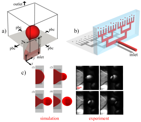
In this work, we simulated a single nozzle out of the full experimental device (see fig. 1 for the sketch of the nozzle
and for a visual comparison between experiment and simulation), using periodic boundary conditions
along cross-flow directions, in order to mimic the effect of neighbour nozzles.
At the inlet and outlet, we imposed uniform velocity profiles via momentum-modified bounceback boundary conditions Bouzidi, Firdaouss, and Lallemand (2001).
Other simulation parameters are the kinematic viscosity , the surface tension of the model and the inlet velocity
(the values are reported in lattice units and chosen so to match the inlet capillary number .
The outlet velocity was chosen in order for the total mass in the system to be conserved, ,
where and are the inlet and outlet sections respectively.
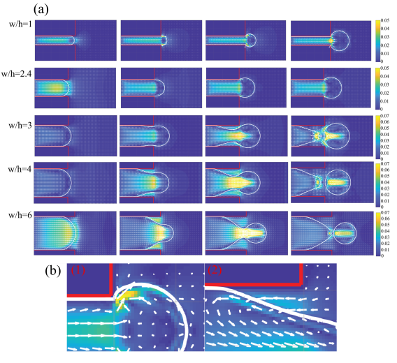
In figure 2, we report the time sequence of the dripping nozzles for different aspect ratios.
In the dripping regime (second to fourth row in figure 2), the continuous phase flows back from the external reservoir to the confined
microchannel (focusing stage) and the flowing jet ruptures as a consequence of the striction induced by such backflow.
Note that the rupture is driven by the negative curvature, which
develops in the striction region (pinching stage). In fig.2, the build-up of a significant backflow is apparent, amounting to about
three times the inlet velocity. As the pinching progresses, the backflow speed decreases, due to the enlarged section available to the continuum phase.
Thus, as pointed out in Montessori et al. (2018a), the breakup should not be interpreted as due to a
Plateau-Rayleigh instability but rather to the backflow of the continuum phase, triggered by the adverse pressure
gradient which arises in correspondence with the focusing of the water jet.
Indeed, the flow inside the nozzle can be regarded essentially as a Hele-Shaw cell in which the nozzle height is the relevant curvature, determining the build up of the capillary pressure ( ) inside the water meniscus.On the other hand, outside the nozzle, the relevant curvature is dictated by the radius of the forming droplet, which grows very quickly thus determining a lower pressure (, being R the radius of the drop) inside the newly forming droplet. Consequently, large pressure gradients develop between the dispersed phase inside the nozzle and the droplet outside which lead to (a) the water drainage from the nozzle (b) the backflow of the oil from the ambient fluid, these two effects finally leading to the droplet rupture
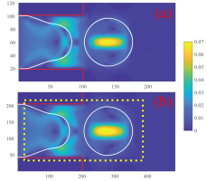
It is worth mentioning that we have tested the convergence of our simulations by carrying
out a set of simulations, for and , by doubling the resolution of the nozzle (see fig. 3).
To this aim, we employed a grid-refinement procedure, as described in Dupuis and Chopard (2003), with the additional requirement
that not only the Reynolds, but also the Capillary number, are kept invariant in the transition from one grid to another.
To ensure this important condition, the surface tension is scaled in such a way as to fulfill the condition:
| (4) |
where and are the kinematic viscosity and surface tension of the refined grid. This permits to employ a refined grid only wherever needed (i.e., around the step emulsifier nozzle), thus significantly alleviating both memory and computing time requirements.
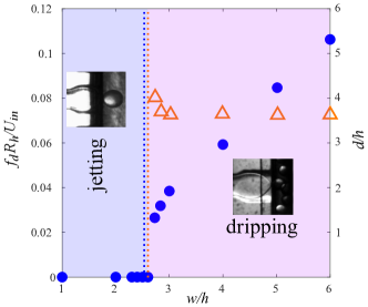
It s now instructive to observe what happens when the width-to-height ratio of the microfluidic nozzle is being varied. The ratio was varied between (square section) and . When , the liquid jet expands isotropically after the sudden expansion and no breakup occurs. The droplet keeps expanding without breaking, in close agreement with the experiments, which give a transition threshold around . Below this value the step emulsifier operates in the jetting mode that occurs whenever the droplet does not break up anymore and starts “ballooning”. Thus, in the jetting mode, the step produces drops with much larger diameter (characterized by a much lower degree of monodispersity) than in the dripping regime. This is precisely what happens both in experiments and simulations. Then, the aspect ratio has been varied between and : the sequences reported in fig. 2, show the nozzles in the dripping regime. As expected, the droplet diameter is approximately constant (roughly , see figure 4) throughout the simulations, confirming that the droplet size is dictated by the height of the nozzle alone, regardless of the aspect ratio, this in line with other experimental evidences Stolovicki, Ziblat, and Weitz (2018). Moreover in figure 4 we report the non-dimensional breakup frequency , being the breakup frequency, as a function of the nozzle aspect ratio. The linear trend reflects the mass conservation, being , where is the inlet discharge which, once is fixed, depends linearly on .
The insets (1) and (2) in figure 2 show the flow field near the solid wall of the nozzle
in the mid-plane for two different aspect ratios namely, and .
In the former case, no re-entrant flow develops, due to the isotropic expansion of the droplet, which prevents
the jet from ”focusing” and the ambient fluid from entering the nozzle.
As a result, no elongational flow develops.
In the latter case (), the anisotropic expansion of the outgoing droplet leads to the necking
of the liquid jet, which breaks up due to the combined effect of the Laplace pressure and the
elongational backflow inside the nozzle.
A question naturally arises: what is the physical mechanism preventing the jet focusing when is small?
In the step emulsifier, when , the fluid can continuously deform from a confined square-section shape to a spherical droplet.
Topologically speaking, the two fluid objects are the same and therefore one can morph into another via
an isotropic expansion, as evidenced in figure 5.
On purely mathematical grounds, it would be interesting to explore whether such isotropic expansion
falls within the class of Ricci flows Brendle (2010), a subject that we leave for future investigations.
On the other hand, when is greater than a critical value, around , the
dynamics (i.e., the backflow driven by adverse pressure gradients) come into play and, although the parallelepiped
and the sphere are still homeomorphic, the fluid undergoes a dynamic rearrangement which guarantees
the curvature to be equilibrated everywhere in the system, in such way that Laplace pressure jumps
remain balanced, until rupture occurs Montessori et al. (2018a).
Thus, the liquid is subject to a rearrangement at the nozzle exit, as evidenced in figure 5, which shows the
typical anisotropic expansion of the liquid jet in the dripping emulsifier, due to the combined effects of
two different mechanisms, namely, a front recession along the flow direction and a necking of the liquid jet occurring crossflow.
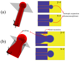
In this sense, surface tension is responsible for the topological breakup i.e., the fluid undergoes a series of (local) dynamical rearrangements in order to balance the pressure differences at the interface, which are not taken into account by a purely topological transformation.
In conclusion, fully three-dimensional, time-dependent simulations shed light on the mechanism which prevents
droplet rupture in step emulsification devices, whenever the nozzle aspect ratio is below , a value in close match with the experimental findings, yielding . When is below such threshold, the liquid jet isotropically expands after the step, inhibiting the necking and preventing the ambient liquid from entering the nozzle and stretch the liquid jet until rupture. Indeed, the dispersed fluid follows a smooth transition from the confined nozzle geometry to the outer ambient, which can be interpreted as a topological isomorphism. However, whenever exceeds the threshold value, a topological breakup is observed, i.e., although the parallelepiped and the sphere are still homeomorphic, the fluid is subject to a series of fluid-dynamical rearrangements, necessary for the curvature at any point of the free surface to keep in balance with the Laplace pressure. Eventually, these rearrangements lead to jet dripping, due to the combined effect of the backflow elongation and the Laplace gradients at the fluid interface. Despite their topological equivalence, this spontaneous symmetry breaking opens a gap between the confined parallelepiped geometry and the outer sphere, so that jet breakup is the only possibility for the former to turn into the latter.
Future work is needed to pin down the values of the breakup threshold , as well as diameter vs step height relation .
Acknowledgements
The research leading to these results has received funding from the European Research Council under the European Union’s Horizon 2020 Framework Programme (No. FP/2014- 2020)/ERC Grant Agreement No. 739964 (COPMAT).
References
- (1) A. Montessori, M. Lauricella, and S. Succi, “Mesoscale modelling of soft flowing crystals,” Philosophical Transaction A 10.1098/rsta.2018.0149.
- Marmottant and Raven (2009) P. Marmottant and J.-P. Raven, “Microfluidics with foams,” Soft Matter 5, 3385–3388 (2009).
- Stolovicki, Ziblat, and Weitz (2018) E. Stolovicki, R. Ziblat, and D. A. Weitz, “Throughput enhancement of parallel step emulsifier devices by shear-free and efficient nozzle clearance,” Lab on a Chip 18, 132–138 (2018).
- Costantini et al. (2015) M. Costantini, C. Colosi, J. Jaroszewicz, A. Tosato, W. Swieszkowski, M. Dentini, P. Garstecki, and A. Barbetta, “Microfluidic foaming: A powerful tool for tailoring the morphological and permeability properties of sponge-like biopolymeric scaffolds,” ACS applied materials & interfaces 7, 23660–23671 (2015).
- Whitesides (2006) G. M. Whitesides, “The origins and the future of microfluidics,” Nature 442, 368 (2006).
- (6) J. O. Hinze, “Fundamentals of the hydrodynamic mechanism of splitting in dispersion processes,” AIChE Journal 1, 289–295, https://onlinelibrary.wiley.com/doi/pdf/10.1002/aic.690010303 .
- Mittal et al. (2014) N. Mittal, C. Cohen, J. Bibette, and N. Bremond, “Dynamics of step-emulsification: From a single to a collection of emulsion droplet generators,” Physics of Fluids 26, 082109 (2014).
- Priest, Herminghaus, and Seemann (2006) C. Priest, S. Herminghaus, and R. Seemann, “Generation of monodisperse gel emulsions in a microfluidic device,” Applied physics letters 88, 024106 (2006).
- Montessori et al. (2018a) A. Montessori, M. Lauricella, S. Succi, E. Stolovicki, and D. Weitz, “Elucidating the mechanism of step emulsification,” Physical Review Fluids 3, 072202 (2018a).
- Bertrandias et al. (2017) A. Bertrandias, H. Duval, J. Casalinho, and M.-L. Giorgi, “Dripping to jetting transition for cross-flowing liquids,” Physics of Fluids 29, 044102 (2017).
- Montessori et al. (2018b) A. Montessori, M. Lauricella, M. La Rocca, S. Succi, E. Stolovicki, R. Ziblat, and D. Weitz, “Regularized lattice boltzmann multicomponent models for low capillary and reynolds microfluidics flows,” Computers & Fluids 167, 33–39 (2018b).
- Succi (2018) S. Succi, The Lattice Boltzmann Equation: For Complex States of Flowing Matter (Oxford University Press, 2018).
- Krüger et al. (2017) T. Krüger, H. Kusumaatmaja, A. Kuzmin, O. Shardt, G. Silva, and E. M. Viggen, “The lattice boltzmann method,” Springer International Publishing 10, 978–3 (2017).
- Gunstensen et al. (1991) A. K. Gunstensen, D. H. Rothman, S. Zaleski, and G. Zanetti, “Lattice boltzmann model of immiscible fluids,” Physical Review A 43, 4320 (1991).
- Leclaire, Reggio, and Trépanier (2012) S. Leclaire, M. Reggio, and J.-Y. Trépanier, “Numerical evaluation of two recoloring operators for an immiscible two-phase flow lattice boltzmann model,” Applied Mathematical Modelling 36, 2237–2252 (2012).
- Leclaire et al. (2017) S. Leclaire, A. Parmigiani, O. Malaspinas, B. Chopard, and J. Latt, “Generalized three-dimensional lattice boltzmann color-gradient method for immiscible two-phase pore-scale imbibition and drainage in porous media,” Physical Review E 95, 033306 (2017).
- Succi (2001) S. Succi, The lattice Boltzmann equation: for fluid dynamics and beyond (Oxford university press, 2001).
- Latva-Kokko and Rothman (2005) M. Latva-Kokko and D. H. Rothman, “Diffusion properties of gradient-based lattice boltzmann models of immiscible fluids,” Physical Review E 71, 056702 (2005).
- Montessori et al. (2015) A. Montessori, P. Prestininzi, M. La Rocca, and S. Succi, “Lattice boltzmann approach for complex nonequilibrium flows,” Physical Review E 92, 043308 (2015).
- Zhang, Shan, and Chen (2006) R. Zhang, X. Shan, and H. Chen, “Efficient kinetic method for fluid simulation beyond the navier-stokes equation,” Physical Review E 74, 046703 (2006).
- Latt and Chopard (2006) J. Latt and B. Chopard, “Lattice boltzmann method with regularized pre-collision distribution functions,” Mathematics and Computers in Simulation 72, 165–168 (2006).
- Benzi, Succi, and Vergassola (1992) R. Benzi, S. Succi, and M. Vergassola, “The lattice boltzmann equation: theory and applications,” Physics Reports 222, 145 – 197 (1992).
- Bouzidi, Firdaouss, and Lallemand (2001) M. Bouzidi, M. Firdaouss, and P. Lallemand, “Momentum transfer of a boltzmann-lattice fluid with boundaries,” Physics of fluids 13, 3452–3459 (2001).
- Dupuis and Chopard (2003) A. Dupuis and B. Chopard, “Theory and applications of an alternative lattice boltzmann grid refinement algorithm,” Physical Review E 67, 066707 (2003).
- Brendle (2010) S. Brendle, Ricci flow and the sphere theorem, Vol. 111 (American Mathematical Soc., 2010).