Tuning topological surface states by cleavage angle in topological crystalline insulators
Abstract
The conducting states, recently discovered at the surface of two special class of insulators – topological insulators and topological crystalline insulators - are distinguished by their insensitivity to local and non-magnetic surface defects at a level of disorder, sufficiently small to be described within the perturbation theory. However, the behavior of the surface states in case of non local macroscopic imperfections is not clear. Here, we propose a systematic study of the topological surface states on vicinal planes (deviations from perfect surface cleavage) in a topological crystalline insulator of the tin telluride family, by using realistic first-principles-derived tight-binding models. The theoretical framework proposed is quite general and easily permits the extensions to other topological insulator families.
pacs:
71.20.−b, 71.70.Ej, 73.20.−r, 73.20.AtI introduction
Topological surface states (TSS), occurring in topological insulators (TI), are, probably, the most exciting and exotic discoveries in condensed matter physics in the last years(Hasan and Kane, 2010; Qi and Zhang, 2011). Experimental realization of the (TI)(Xia et al., 2009; Zhang et al., 2009) paves the way to numerous potential technological applications: the quantum spin Hall effect, the dissipationless spin current, the magnetoelectric effect (Kane and Mele, 2005; Bernevig et al., 2006; Xu and Moore, 2006; Qi et al., 2008) etc. The discovery of TSS has opened a race to search for topological states protected by some other symmetries. Along this line, the theoretical proposal of Fu about the TSS protected by crystalline symmetry (Fu, 2011; Slager et al., 2012, 2015; Kruthoff et al., 2017; Slager, 2018) has soon found experimental confirmation (Xu et al., 2012; Hsieh et al., 2012; Tanaka et al., 2012) in tin telluride (IV-VI) family and stimulated intense work on the search for materials in the new class of topological crystalline insulators (TCI). At variance with the conventional TI, where the protection of the TSS comes from time-reversal symmetry, in TCI the protection is ensured by the crystalline symmetry, usually the mirror symmetry. TCI are characterized by a new topological invariant - the so-called mirror Chern number - analogously to the TI, which are characterized by the topological invariant. A system can be a trivial TI, but possess a non-zero , which is exactly the case of tin telluride SnTe – a prototypical TCI. For the firm observation of topological states in experiments it is crucial to know how the defects of various types, always present in real materials, could influence the TSS. Thanks to the topological protection, the TSS should be quite robust against the local (non-magnetic) surface defects. Moreover, it was demonstrated recently that the TSS are also insensitive to the disorder in the bulk (Di Sante et al., 2015).
A different type of defect can be described as a slight deviation of the surface cut from the most common and highly symmetric one. Indeed, the particularity of the TSS lies in the fact that they only appear on the particular cuts of the bulk crystal (e.g. in SnTe, the topological surfaces are , and c.f. Ref.Safaei et al., 2013). In the real experiment, the surface might not be cleaved precisely at the right angle and, therefore, a legitimate question arises: to which extent the crystal surface can deviate from the ideal one so that the TSS are still present? For completeness, we note that in the case of topological insulators the answer is quite clear: strong topological insulators will have SS on every surface, while weak ones only on some of them depending on how the time-reversal symmetry (TRS) points are projected on the surface Fu and Kane (2007), while no conclusion a priori can be made for TCI. It was pointed out in Ref. Hsieh et al., 2012 that TSS arise in SnTe if the projections of the TRS points on the surface possess the mirror symmetry. Thus, one needs not only to trace the projections of the TRS points, but also to make sure that these projections lie within a mirror plane.
To answer the above question, realistic, material-specific calculations of large systems are needed. The ab-initio methods can easily reach their computational limits due to the mandatory use of the spin-orbit coupling in the simulations and the need to well exceed the critical slab thickness in order to observe the TSS. Thus, one resorts to the realistic tight-binding models with the parameters chosen so as to reproduce the ab-initio band-structure. In this way, large super-cell calculations can be easily afforded at low computational cost, while conserving the predictive power of ab-initio approaches. In such a study, the tin telluride family (SnTe, Pb1-xSnxSe, and Pb1-xSnxTe) represents almost an ideal playground thanks to the simplicity of the unit cell and the richness of the phase diagram.
In SnTe and in other tellurides, vicinal planes represent a commonly occurring example of a non-ideally cleaved surface Deringer and Dronskowski (2015); Sessi et al. (2016); Zallo et al. (2017). In this article we study the TSS on vicinal surfaces, which deviate from the ideal ones. To achieve this, we construct the super-cells with the so-called tilted boundary conditions, so that one of the boundaries of the super-cell appears to make a finite angle with respect to the crystallographic axes of the unit cell. As we will show below, in this case, there is always at least one mirror plane, which is perpendicular to the tilting axis and to the tilted surface and which passes through some of the projections of TRS points, thus ensuring the mirror symmetry in those projections.
In this setup, some of the TSS will have the topological protection, since they are projections of bulk TRS and have a mirror plane, although their precise positions and the form of band dispersion is to be determined. We combine high performance slab calculations with the TRS projection analysis and show how the topologically protected and unprotected states evolve upon changing the cleavage angle with respect to the three topological surfaces in SnTe.
II methods
We perform Density functional theory (DFT) simulations using the Vienna Ab initio Simulation Package (VASP) (Kresse and Joubert, 1999) and the Generalized Gradient Approximation (GGA)(Perdew et al., 1996) in the Perdew-Burke-Ernzerhof (PBE) formalism for the exchange-correlation potential. We use an energy cutoff for the plane wave basis of eV and a Monkhorst-Pack point mesh(Monkhorst and Pack, 1976). Here we consider , and surfaces in the cubic phase. To calculate TSS in the slab geometry, the number of layers has to be sufficiently large to prevent the interaction between TSS of the two slab surfaces, which makes ab-initio approaches prohibitive. We, therefore, resort to an effective tight-binding (TB) model. The TB hopping matrix elements are determined by projection of the ab-initio VASP Hamiltonian onto the atomic-like orbitals through the WANNIER90 package(Mostofi et al., 2008). In these projections we retain - and -type basis functions. As for structural parameters, we employ those optimized within DFT-GGA. For the cubic structure, we use lattice constant Å, rhombohedral angle in the unit cell with center of inversion (see Supplemental Materials in Ref.Plekhanov et al., 2014.)
In order to safely conclude about the presence of TSS, we plot the 2D band structure for the slabs with maximal possible thickness. This essentially stands for many diagonalisations (as many as the number of surface -points) of rather large complex Hermitian matrices (up to in this work). We solve this technical problem by employing parallel GPU diagonalization routines and CUDA/C/Fortran interfaces.
We explain now the geometry conventions used in the present work in order to define the tilted or vicinal planes. It is well known that in SnTe the TSS are only present on three crystallographic surfaces. These are , and (Safaei et al., 2013). Each of these cases corresponds to a unit cell, which possesses the corresponding surface. Here we consider each of these unit cells with unit vectors and build a new unit cell with unit vectors , so that each is a linear combination of with integer coefficients, so that always contain an integer number of original cells . We choose the original cells to be orthorhombic and double if necessary the primitive cell. For completeness we report below both the original cell and the tilted one geometries.
III results
III.1 Tilted (001) surfaces
The case of tilted surfaces is the most straightforward one. We start from a tetragonal unit cell () which has the following unit vectors (in Cartesian coordinates): , so that is perpendicular to surface. Here is the SnTe lattice constant. The unit vectors of tilted cell are expressed in Cartesian coordinates as follows:
It is easy to see that , while , and is rotated by an angle around with respect to . This cleavage angle can be found as: . This choice of basis ensures the orthorhombicity of the unit cell and allows to build up a sequence of surfaces with the cleavage angle gradually approaching zero. Such a choice ensures minimal cluster size at a given angle . The values of and explored in the present work are listed in Tab.1.
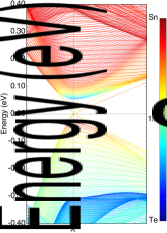
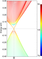
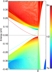
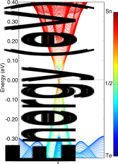
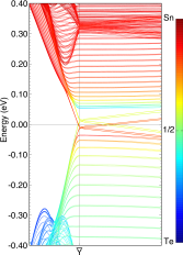
At (the pristine surface), there are two mirror planes: and . It it easy to see that at finite the mirror plane is lost, while the is preserved since the rotation axis is normal to it. Therefore, we conclude that the projections of the TRS points on a tilted surface will have the topological protection if they lie within the mirror plane. We will show below that this is indeed the case and derive the general rule describing the location of TSS for given and . An example of the slab dispersion containing TSS in the case of , is shown in Fig. 1.
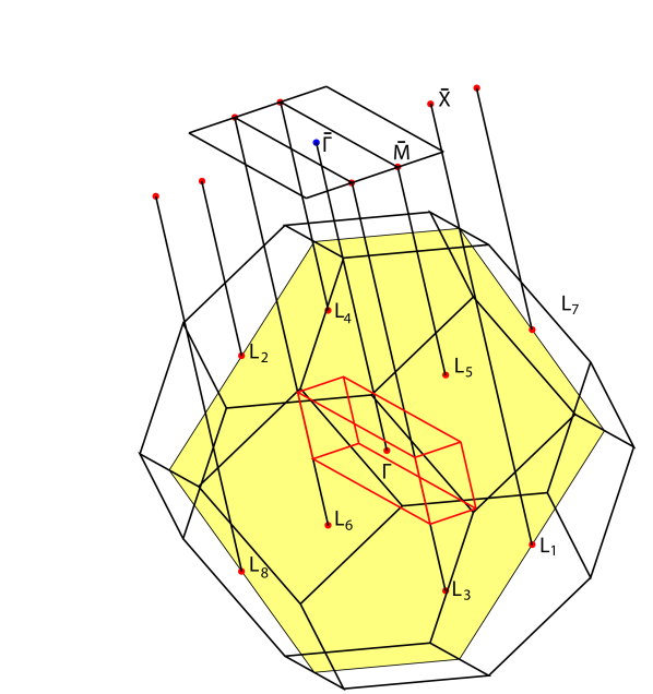
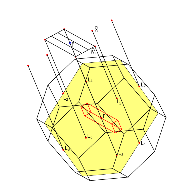
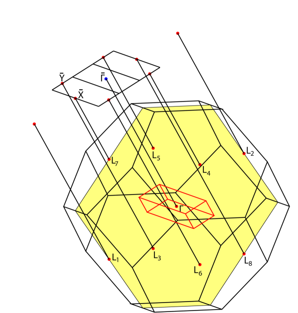
The surface states appear at high-symmetry points of the surface Brillouin zone depending on the parity of and independently on . Namely, for even , the surface states are located at and , while for odd they are at and . This alternation rule holds for all values of and can be understood if one takes into account how points of the original rhombohedral BZ are projected onto the surface BZ of tilted unit cell. Nevertheless, the topological protection is only ensured for the and points as they are crossed by the mirror plane, while and are not protected by the mirror symmetry. We report the 3D plots of such projections for in Fig.2.
It can be seen from Fig. 1, how the lack of topological protection changes the low-energy physics. Namely, at , a tiny gap opens, while at there are topological states. The reason for this tiny gap is the numerical round-off errors inevitable in any numerical calculation. Mirror symmetry at make the TSS insensible to these errors, while at there is no such protection. It is interesting to note that each of the eight points of the first primitive BZ is projected onto a different (or ) point in different folded surface BZ. Moreover, already at minimal the projections of some of the points in the first bulk BZ belong to higher surface BZs. As (and ), the projections move more and more towards higher surface BZs. On the other hand, as , the extension of the surface BZ along direction tends to zero as well as the difference between and and between and . In addition, in this limit the mirror plane is restored. Therefore, in the limit each surface TRS point acquires the projections from two points, which then form a bonding and anti-bonding combinations - a well known fact for TSS in SnTe.(Hsieh et al., 2012; Polley et al., 2018). Thus studying tilted states allows to approach this limit gradually and observe the progressive transformation of TSS.
| TP | TNP | ||||
|---|---|---|---|---|---|
III.2 Tilted (111) surfaces
In the case of tilted surfaces, the original (non-tilted) unit cell is hexagonal and has the following unit vectors in Cartesian coordinates: . However, this cell is not orthorhombic, therefore, we double and rotate it by (, ) to end up with an orthorhombic unit cell having, . As above, we rotate around , which becomes the new . We require that , then, in general:
The condition of orthogonality imposes only one equation for four unknowns. In order to minimize the size of , we set , and since , while , we arrive at the constraint
| (2) |
for the remaining three parameters. In Cartesian coordinates, the unit vectors of tilted cell are expressed as follows:
with the constraint (2). This choice of basis ensures the orthorhombicity of the unit cell and allows to build up a sequence of surfaces with the cleavage angle gradually approaching zero. The cleavage angle in this setting depends only on as follows: , thanks to the constraint (2).
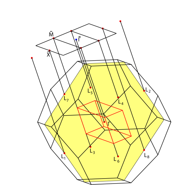
At (the pristine surface), there are three mirror planes: , and . It it easy to see that at finite the mirror planes and are lost, while the is preserved since the rotation axis is normal to it. Therefore, we conclude that the projections of the TRS points on a tilted surface will have the topological protection if they lie within the mirror plane. As we will show below, there are always such TSS along with those without topological protection. We also derive the general rule describing the location of TSS for given , and .
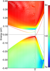
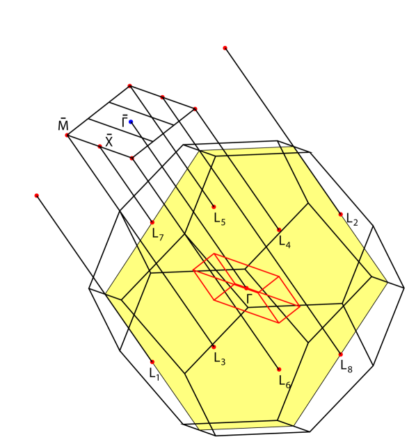
The values of explored in the present work are listed in Tab.2. An example of the slab dispersion with and without topological protection in the case of , and is depicted in Fig. 3. Once again there is a nice odd-even alternation rule: for even the surface states appear at and , while for odd - at and , as illustrated in Fig. 4. Nevertheless, the topological protection is only ensured for the points as they are crossed by the mirror plane, while , and are not protected by the mirror symmetry. When increases, the area of the first surface Brillouin zone progressively diminishes, while the projections of the TRS points move towards higher surface Brillouin zones, as in the case of the tilted surfaces. In the limit the TRS projections turn to the usual picture seen on surfaces. We notice that the alternation rule for TSS on surface does not depend on values of and but only on .
It is interesting to see how the lack of topological protection at on Fig. 3 leads to opening of a gap between the anion and cation topological states on the left of point.
| TP | TNP | |||||
|---|---|---|---|---|---|---|
III.3 Tilted (110) surfaces
| TP | TNP | ||||
|---|---|---|---|---|---|
The original cell in this case reads as: , so that it has the pristine perpendicular to the surface. This unit cell can be viewed as a unit cell from Subsec.III.1 with the vectors and interchanged. We have used the following unit cell basis sets for this family of surface states
in Cartesian coordinates. It means that:
This choice of basis ensures the orthorhombicity of the unit cell and allows to build up a sequence of surfaces with the cleavage angle gradually approaching zero. The cleavage angle in this setting reads as follows: . It is easy to see that as the unit cell in this case is the same as in Sec. III.1. The pristine unit cell is recovered in the limit , . The values of explored in the present work are listed in Tab.3.
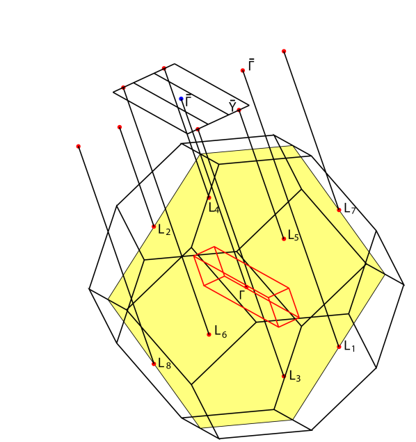
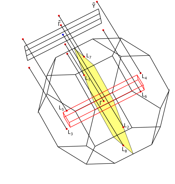
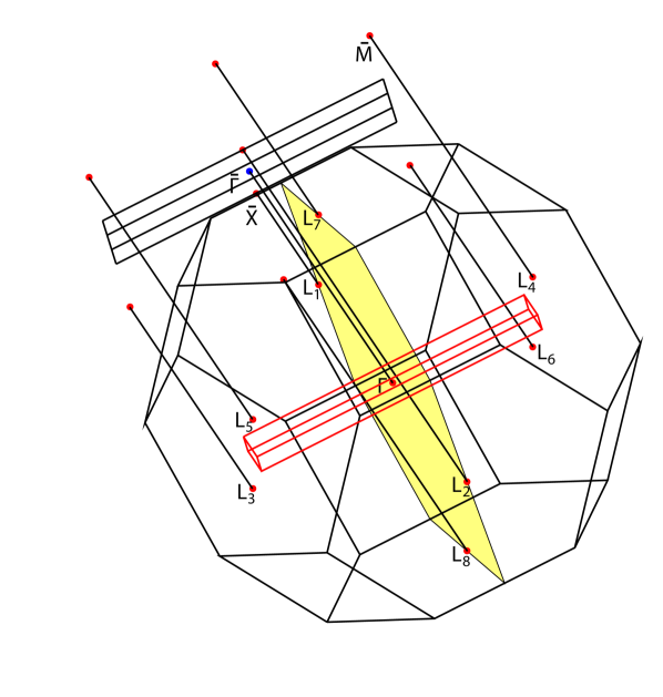
Since and are the same as in Sec. III.1, the appearance of the surface states follow the same rule outlined therein, namely independently on , and depending on parity of . The difference with respect to the case of Sec. III.1 is that the limit of small now is realized at as opposed to . We report the 3D plots of such projections for in Fig.5. It is interesting to note that each of the eight points of the first primitive BZ is projected onto a different high symmetry point in different folded surface BZ. Moreover, the projections of some of the points in the first bulk BZ belong to higher surface BZs. As (and ), the projections move more and more towards higher surface BZs. On the other hand, as , the extension of the surface BZ along direction tends to zero as well as the distance between and . We emphasize, that only and surface states have the topological protection, while and do not. An example of the slab dispersion containing TSS in the case of and is depicted in Fig. 6.
IV Conclusion
In this manuscript we performed a systematic study of topological surface states on vicinal planes with finite cleavage angle of the TCI tin telluride, by using the ab-initio derived effective tight-binding model. We have set up TB calculations of slabs thick enough to observe the topological surface states. We showed that the choice of vicinal plane has a direct consequence on the observed topological states, and in particular on the number of the surface states and their positions. We also discuss the limits and recovered the usual TSS in SnTe. In particular, we found an alternation rule, determining the position of the TSS based on the parity of one of the integers, used to construct the folded unit cell. These integers, in turn, can be related to the cleavage angle of the surface. In all the cases, the TSS appear at high-symmetry points and as opposed to the limiting case and where an exact coincidence of the projections of two points with a subsequent hybridization and a shift off the high symmetry point occurs. In the case of the vicinal plane surface states, only some of the states are topologically protected by the mirror plane symmetry and are thus the topological surface states, contrarily to the case of the pristine surfaces where all the TRS projections are topological surface states. Our conclusions hold for arbitrary angles and orientations of the tilted surfaces. The direct calculation of the mirror Chern numbers for the vicinal planes is in progress.
A singular feature of the TSS projected onto the tilted vicinal planes consists in the fact that at small angles , the bulk TRS points from the first bulk Brillouin zone are projected not only onto the first surface Brillouin zone but also to the higher ones.
This work was supported by EPSRC (grants EP/R02992X/1). C.W. gratefully acknowledges the support of NVIDIA Corporation with the donation of the Tesla K40 GPUs used for this research. For computational resources, we were supported by the ARCHER UK National Supercomputing Service and the UK Materials and Molecular Modelling Hub for computational resources (EPSRC Grant No. EP/ P020194/1).
References
- Hasan and Kane (2010) M. Z. Hasan and C. L. Kane, Rev. Mod. Phys. 82, 3045 (2010).
- Qi and Zhang (2011) X.-L. Qi and S.-C. Zhang, Rev. Mod. Phys. 83, 1057 (2011).
- Xia et al. (2009) Y. Xia, D. Qian, D. Hsieh, L. Wray, A. Pal, H. Lin, A. Bansil, D. Grauer, Y. S. Hor, R. J. Cava, and M. Z. Hasan, Nat Phys 5, 398 (2009).
- Zhang et al. (2009) H. Zhang, C.-X. Liu, X.-L. Qi, X. Dai, Z. Fang, and S.-C. Zhang, Nat Phys 5, 438 (2009).
- Kane and Mele (2005) C. L. Kane and E. J. Mele, Phys. Rev. Lett. 95, 146802 (2005).
- Bernevig et al. (2006) B. A. Bernevig, T. L. Hughes, and S.-C. Zhang, Science 314, 1757 (2006).
- Xu and Moore (2006) C. Xu and J. E. Moore, Phys. Rev. B 73, 045322 (2006).
- Qi et al. (2008) X.-L. Qi, T. L. Hughes, and S.-C. Zhang, Phys. Rev. B 78, 195424 (2008).
- Fu (2011) L. Fu, Phys. Rev. Lett. 106, 106802 (2011).
- Slager et al. (2012) R.-J. Slager, A. Mesaros, V. Juričić, and J. Zaanen, Nature Physics 9, 98 (2012).
- Slager et al. (2015) R.-J. Slager, L. Rademaker, J. Zaanen, and L. Balents, Phys. Rev. B 92, 085126 (2015).
- Kruthoff et al. (2017) J. Kruthoff, J. de Boer, J. van Wezel, C. L. Kane, and R.-J. Slager, Phys. Rev. X 7, 041069 (2017).
- Slager (2018) R.-J. Slager, Journal of Physics and Chemistry of Solids (2018), 10.1016/j.jpcs.2018.01.023.
- Xu et al. (2012) S. Xu, C. Liu, N. Alidoust, M. Neupane, D. Qian, I. Belopolski, J. Denlinger, Y. Wang, H. Lin, L. Wray, G. Landolt, B. Slomski, J. Dil, A. Marcinkova, E. Morosan, Q. Gibson, R. Sankar, F. Chou, R. Cava, A. Bansil, and M. Hasan, Nature Comms. 3, 1192 (2012).
- Hsieh et al. (2012) T. H. Hsieh, H. Lin, J. Liu, W. Duan, A. Bansil, and L. Fu, Nat. Comm. 3, 982 (2012).
- Tanaka et al. (2012) Y. Tanaka, Z. Ren, T. Sato, K. Nakayama, S. Souma, T. Takahashi, K. Segawa, and Y. Ando, Nature Phys. 8, 800 (2012).
- Di Sante et al. (2015) D. Di Sante, P. Barone, E. Plekhanov, S. Ciuchi, and S. Picozzi, Scientific Reports 5, 11285 (2015).
- Safaei et al. (2013) S. Safaei, P. Kacman, and R. Buczko, Phys. Rev. B 88, 045305 (2013).
- Fu and Kane (2007) L. Fu and C. L. Kane, Phys. Rev. B 76, 045302 (2007).
- Deringer and Dronskowski (2015) V. L. Deringer and R. Dronskowski, Angewandte Chemie International Edition 54, 15334 (2015).
- Sessi et al. (2016) P. Sessi, D. Di Sante, A. Szczerbakow, F. Glott, S. Wilfert, H. Schmidt, T. Bathon, P. Dziawa, M. Greiter, T. Neupert, G. Sangiovanni, T. Story, R. Thomale, and M. Bode, Science 354, 1269 (2016).
- Zallo et al. (2017) E. Zallo, S. Cecchi, J. E. Boschker, A. M. Mio, F. Arciprete, S. Privitera, and R. Calarco, Scientific Reports 7, 1466 (2017).
- Kresse and Joubert (1999) G. Kresse and D. Joubert, Phys. Rev. B 59, 1758 (1999).
- Perdew et al. (1996) J. P. Perdew, K. Burke, and M. Ernzerhof, Phys. Rev. Lett. 77, 3865 (1996).
- Monkhorst and Pack (1976) J. Monkhorst and J. D. Pack, Phys. Rev. B 13, 5188 (1976).
- Mostofi et al. (2008) A. Mostofi, J. R. Yates, Y.-S. Lee, I. Souza, D. Vanderbilt, and D. Marzari, Comput. Phys. Commun. 178, 685 (2008).
- Plekhanov et al. (2014) E. Plekhanov, P. Barone, D. Di Sante, and S. Picozzi, Phys. Rev. B 90, 161108 (2014).
- Polley et al. (2018) C. M. Polley, R. Buczko, A. Forsman, P. Dziawa, A. Szczerbakow, R. Rechciński, B. J. Kowalski, T. Story, M. Trzyna, M. Bianchi, A. Grubišić Čabo, P. Hofmann, O. Tjernberg, and T. Balasubramanian, ACS Nano 12, 617 (2018).