Nanoscale angular lattice formed by light with high orbital angular momentum
Abstract
Standing waves generated by the interference of Laguerre-Gaussian (LG) beams can be used for dipole trap. We propose a scheme to create a nanometer (nm) scale ring lattice based on the interference of two high order LG beams without decrease the wavelength. Both of the two LG beams have a monocyclic intensity distribution, and they have the same orbital angular momentum (OAM) quantum number on the order of . We are able to theoretically demonstrate a dipole potential along angular direction with the period of 1 nm , given the waist of the Gaussian beams to be 0.8 m. The atoms in this lattice can be trapped along the radial and azimuthal direction in the potential wells of with 100 nm and 0.85 nm distance. The proposed method opens up a convenient pathway towards sub-wavelength atom traps that could directly lead to overlap of wave function of atoms in adjacent wells and the formation of molecular bonds.
pacs:
67.85.-d, 37.10.Gh, 42.60.JfI. Introduction
The angular momentum of light can be divided into the spin part and orbital part Bekshaev11 , while the spin angular momentum (SAM) that is related to the polarization of the light, and the orbital part is related to the orbital angular momentum (OAM)of light beams. Since firstly found by L. Allen in 1992, that laser with Laguerre-Gaussian (LG) amplitude distribution have a well-defined OAM Allen92 , light and particle beams with OAM have drawn attention of researchers in various fields Lloyd17 ; Devlin17 , such as optical tweezer based on transferring OAM from light to matter particles He95 ; MacDonald02 , atom guiding and trapping Wright00 , and exotic excitation of atoms Scholz14 ; Rodrigues16 ; Afanasev14 .
The angular lattice, which is formed by standing waves originated from the interference of two LG beams with nonzero OAM, can also be used into atom trapping Franke07 ; Huang16 ; Rhodes06 . The period of interference mode in angular direction is proportional to , where is the OAM quantum number of the LG beam, and is not limited by the wavelength of LG beams. This can be used as novel way of creating the small period lattice without demanding short wavelength of the laser.
On the other hand, it is of crucial importance in ultracold atom physics to realize optical lattice beyond the diffraction limit. In 2013, Cirac et al. proposed a magnetic lattice for ultracold atoms on the scale of few tens of nanometers Nascimbene15 ; Wang18 ; Romero13 . However, the smallest period of the proposed sub-wavelength optical lattices have not yet reached sub-10 nm scale, in such length scale, the wave functions of atoms in adjacent traps could overlap. This can lead to exciting new physics, such as direct observation of molecular bond formation in such lattices and creation of novel molecular structures LRLiu13 .
There are various methods to generate OAM carrying light beams McGloin05 ; Guti rrez00 ; Bandres04 , e.g. using spiral phase plate (SPP) and spiral phase mirrors (SPM) as mode converter Beijersbergen93 ; Heckenberg92 ; Turnbull96 ; Arlt98 ; Fickler16 and holographic method Courtial97 . The latter method avoids using thick lenses and can produce LG beam with OAM exceeding . According to the quantum theory, the orbital angular momentum can, in principle, be arbitrarily large Fickler16 .
In this work, we theoretically present a novel scheme to create sub-nm scale optical lattices based on the high order LG beams. We demonstrate that an angular optical dipole lattice can be obtained from IR laser with 1 nm period, which is close to the scale of lattices in realistic solid state materials. The angular lattice formed by such LG beams can be more benign to atoms, while the lattice of x-ray laser with the similar wavelength must destroy the structure of the atoms and molecules within 100 fs through photoionization and subsequent Coulomb explesion Barty12 .
This work is organized as follows: In Section II, we introduce the related properties of the LG beams and calculate the optical dipole potential (ODP) generated by the interference of LG beams. In Section III, we solve the ground state of a single atom in this ODT. Finally, in Section IV, we present the wave function of single 87Rb atom in this angular lattice formed by two LG beams with wavelength of 780 nm.
II. The Laguerre Gaussian beams and the optical dipole potential
The circularly symmetric LG beam is denoted by where is the quantum number of azimuthal mode, and the beams with give rise to a well-defined OAM of per photon Allen92 . is the quantum number of radial mode with nodes.
The normalized field amplitude distribution of an mode laser beam can be written as Clifford98
| (1) | |||
where is the longitudinal distance from the beam waist (see Fig. 1). is the power of laser beams, is the radius at which the Gaussian beam intensity falls to of its axis value while is the beam waist at , is the associated Laguerre polynomial, is the azimuthal angle, is the Rayleigh range for the laser with wavelength , and is the Gouy phase. We focus on the case of , where the associated Laguerre polynomial and only a single ring is present in the beam intensity profile with the maximum intensity at the toroid radius Arlt00
| (2) |
This maximum intensity is reached at the waist () and is given by
| (3) |
As the result of fixed toroid radius , when the maximum value of intensity increases with the azimuthal index , the radial intensity profile of the beam must become sharper (see Fig. 1 (b), showing the normalized intensity versus normalized radius for different azimuthal index with the same laser power).
For a circularly polarized beam propagating in the longitudinal z-direction, the linear momentum density could be separated into , and Allen00 :
| (5) | |||
where , and Allen00 are the linear momentum densities in radial, angular and longitudinal directions, respectively. In particular, the first and the second terms of relate to the orbital angular momentum (OAM) and SAM of a single photon Allen92 .
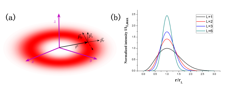
In Fig. 1(a) we show the linear momentum density of a linearly polarized LG beam propagating in the z-direction. For linear polarized beams, we have , and counter-rotating momenta for beams carrying OAM of opposite signs.
Assuming the laser is linearly polarized, two LG beams propagating in the opposite direction with the same azimuthal index can interfere, and form standing waves in the angular direction MacDonald02 . We write the intensity of the interfering beams in the plane of as
| (6) |
where is the maximum intensity for . As one can see from Eq.(7), the interference of and beams create an angular lattice with nodes in the azimuthal direction.
As one can see from Eq.(6), the intensity distribution of the interference mode depends on two independent variables and . In other words, can be rewrite as which is the separation of variables. The line shape of is actually , while has a shape shown in Fig. 1(b),it varies in the form of .
Since the period of the interference mode at the beam waist scales as , the distance of interval between adjacent traps is not limited by the laser wavelength, and can reach sub-nm scale by already obtainable laser technology.
The atoms in laser fields experience dipole potential resulted from the interaction of induced atomic dipole and light field Riis ; Grimm00 . Though for a laser field with spatial modulation at nm scale, the non-dipole effect can emerge due to inhomogeneity of field intensity in the space in which the atomic and molecular wave functions are distributed, we take here the dipole potential as the first order approximation.
Considering and transitions of the 87Rb atom in linearly polarized laser field, the ODP can be expressed as Grimm00
| (7) |
where is the detuning of transition, is the natural line width of the optical transition and is the central frequency of the laser. The ODP is extremely analogous to the intensity distribution derived from the interference of two LG beams. In this above equation, all of the parameters other than intensity distribution are only related to the atomic properties. For a given atom, the magnitude and shape of the ODT are entirely determined by the intensity distribution of the interference mode.
III. Bound state in the angular lattice
For the proposed optical lattice with 1 nm period, we calculate the bound state of 87Rb atom inside, the Hamiltonian of which reads
| (8) |
where the first term refers to the kinetic energy of the atom in polar coordinates , and is the dipole potential of the atom in the plane of i.e. the position of Gaussian beam waist.
We use the perturbation theory to solve the ground state of the system. Firstly, the optical dipole potential in radius direction would be sharper and tighter as grows. The atom trapped in a vicinity near . We can write the kinetic term approximately as and further as due to the dominant term.
In this paper, the ODT we study is composed of two red-detuned LG beams with a wavelength of 780 nm. The atom could be trapped at a maximum of laser intensity in each direction. As we have shown in Fig. 1(b), for a deep ODP, it is a good approximation to treat this ODT as a harmonic trap by means of second order perturbation. For this red-detuning induced ODT, We performed Taylor expansion at and respectively, and truncated it to the second order. The final form of ODT is:
| (9) |
using the relation .
Suppose the 87Rb atom is placed in the plane of the counter-propagating LG beams with wavelength nm. With a fixed the toroid radius with mm. Which means that when we change the OAM quantum number , Gaussian laser radius has to vary as synchronously. At the same time, in order to ensure the bound states of atoms in the ODT in the case of high , we take the laser power as mW while the detuning form line 21.483 GHz. For such near-resonance laser beams, the scattering effects of atomically stimulated absorption of photons and subsequent spontaneous reemission will not be negligible. One possible way to inhibit the spontaneous emission is to place the device in a cavity which all of normal mode are far off-resonance with respect to the atomic transition frequency Grimm00 ; Th98 .
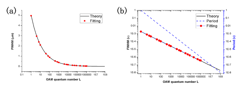
According to the expression of ODT in Eq.(9) and our approximation, for a fixed radialus (azimuthal), the ODT in azimuthal (radial) direction could be regarded as a harmonic trap. The ground state in the harmonic trap is actually Gaussian shape. Thus, we calculate the full width at half maximum (FWHM) of this ground state Gaussian wave function, which can be written as:
| (10) | |||
In Fig. 2(a) and (b), we show the results of the theoretical model (filled red circus) and numerical calculations without harmonic approximation (black solid line) in the and direction. FWHM and FWHM vary as and with the increase of . We only perform Gaussian fitting with wavefunction of and , where is the ground state of the atom in ODT.
IV. Sub-wavelength optical lattice with nm period
For the ring lattice we discussed in this article, there are lobes in the azimuthal direction, the period of each lobe vary as , we show this (the blue dashed line) in Fig. 2(b), as a comparison with FWHM of ground state wave packet in direction. When , the period of each fragment drops to 1 nm in the form of where mm. At the same time, the waist of Gaussian beams is required as 0.8 m, which is well below the diffraction limit of the nm lasers, and is in principle feasible, since for a parallel beam of diameter passing through a convex lens with focal length , it can be focused to a waist of .
In order to ensure the trapping efficiency of the ODT to atoms, the laser power is taken as mW. In Fig. 3(b), we demonstrated that the FWHM of ground state wave packet varies as while the period of ODT in angular direction decrease as . The drops faster than FWHMϕ as grows and there is also a cross between them, while FWHMϕ is much smaller than when . And the purpose of the parameters we take is to make this cross point appear when . As shown in Fig. 2(b), the period of the angular lattice decrease with , there is a limitation for this angular lattice of for mW and GHz.
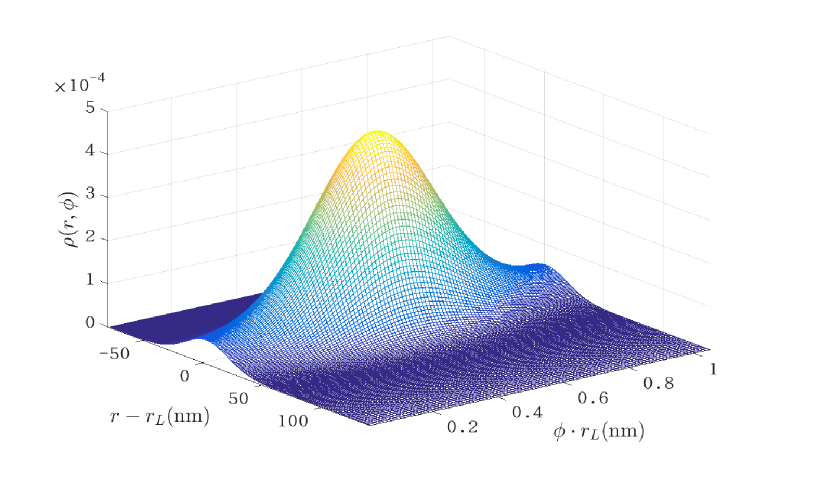
For , we take the grid for coordinate in nm and for in , respectively. In order to simplify the calculation, we isolate one period of the optical dipole lattice, and discretize it on a radial-angular mesh in the discrete variable representation (DVR) Colbert92 . We use the multi-configuration multi-layer time-dependent Hartree (ML-MCTDH) method Cao13 ; KCao13 ; KCao17 to calculate the spatial distribution of ground state 87Rb atom in the optical lattice (see Fig. 3). The calculated one-body density proves the fact that the 87Rb atom can be tightly trapped in a small area of 1 nm spacing in the angular direction.
Conclusion
In this paper, we propose a scheme to create an optical lattice of nm scale with two high order LG beams, with OAM quantum number . The radial distribution of dipole trap is monocyclic distribution with the width of mm. The wells in angular direction, form an angular lattice with the period of nm. We calculate the one-body density of single 87Rb atom in a segment of the angular lattice and find that the atom can be trapped in a extremely narrow area. Since there is no fundamental limitation for the period to reach sub-nm scale, directly manipulating atoms to form molecules can be made possible, with further possibility of flexible 3D shaping of molecular structures based on 3D arrays of traps Barredo18 .
For a laser fields with optical modulation at nm scale, the non-dipole effect can be much more pronounced for the atoms interacting with proposed optical lattice, this will be adducted in the future work.
Acknowledgements
We thank Li You, Jochen Kuepper and Henning Moritz for helpful discussions. This work was supported by the National Natural Science Foundation of China (Grants No. 11604107). Z.L. thanks Volkswagen Foundation for partial financial support through Peter Paul Ewald Fellowship.
References
- (1) A. Bekshaev, K.Y. Bliokh, M. Soskin, Internal flows and energy circulation in light beams, Journal of Optics, 13 (2011) 053001.
- (2) L. Allen, M.W. Beijersbergen, et al. Orbital angular momentum of light and the transformation of Laguerre-Gaussian laser modes, Physical Review A, 45 (1992) 8185-8189.
- (3) S.M. Lloyd, M. Babiker, et al. Electron vortices: Beams with orbital angular momentum, Reviews of Modern Physics, 89 (2017).
- (4) R.C. Devlin, A. Ambrosio, et al. Arbitrary spin-to-orbital angular momentum conversion of light, Science, (2017).
- (5) H. He, M.E. Friese, et al. Direct observation of transfer of angular momentum to absorptive particles from a laser beam with a phase singularity, Phys Rev Lett, 75 (1995) 826-829.
- (6) M.P. MacDonald, L. Paterson, et al. Creation and Manipulation of Three-Dimensional Optically Trapped Structures, Science, 296 (2002) 1101-1103.
- (7) E.M. Wright, J. Arlt, K. Dholakia, Toroidal optical dipole traps for atomic Bose-Einstein condensates using Laguerre-Gaussian beams, Physical Review A, 63 (2000).
- (8) H.M. Scholz-Marggraf, et al. Absorption of twisted light by hydrogenlike atoms, Physical Review A, 90 (2014).
- (9) J.D. Rodrigues, L.G. Marcassa, et al. Excitation of high orbital angular momentum Rydberg states with Laguerre CGauss beams, Journal of Physics B: Atomic, Molecular and Optical Physics, 49 (2016) 074007.
- (10) A. Afanasev, C.E. Carlson, A. Mukherjee, Two properties of twisted-light absorption, Journal of the Optical Society of America B, 31 (2014) 2721.
- (11) S. Franke-Arnold, J. Leach, et al. Optical ferris wheel for ultracold atoms, Optics Express, 15 (2007) 8619-8625.
- (12) S. Huang, Z. Miao, et al. Composite vortex beams by coaxial superposition of Laguerre CGaussian beams, Optics and Lasers in Engineering, 78 (2016) 132-139.
- (13) D.P. Rhodes, D.M. Gherardi, et al. Atom guiding along high order Laguerre CGaussian light beams formed by spatial light modulation, Journal of Modern Optics, 53 (2006) 547-556.
- (14) S. Nascimbene, N. Goldman, et al. Dynamic Optical Lattices of Subwavelength Spacing for Ultracold Atoms, Phys Rev Lett, 115 (2015) 140401.
- (15) Y. Wang, S. Subhankar, et al. Dark State Optical Lattice with a Subwavelength Spatial Structure, Phys Rev Lett, 120 (2018) 083601.
- (16) O. Romero-Isart, C. Navau, A. Sanchez, P. Zoller, J.I. Cirac, Superconducting vortex lattices for ultracold atoms, Phys Rev Lett, 111 (2013) 145304.
- (17) L. R. Liu, J. D. Hood, Y. Yu, J. T. Zhang, N. R. Hutzler, T. Rosenband, K.-K. Ni, Building one molecule from a reservoir of two atoms, Science 369, 900 (2018).
- (18) D. McGloin, K. Dholakia, Bessel beams: Diffraction in a new light, Contemporary Physics, 46 (2005) 15-28.
- (19) J.C. Guti rrez-Vega, M.D. Iturbe-Castillo, S. Ch vez-Cerda, Alternative formulation for invariant optical fields: Mathieu beams, Opt. Lett., 25 (2000) 1493-1495.
- (20) M.A. Bandres, J.C. Guti rrez-Vega, Ince CGaussian beams, Opt. Lett., 29 (2004) 144-146.
- (21) M.W. Beijersbergen, L. Allen, et al. Astigmatic laser mode converters and transfer of orbital angular momentum, Optics Communications, 96 (1993) 123-132.
- (22) N.R. Heckenberg, R. McDuff, et al. Generation of optical phase singularities by computer-generated holograms, Opt. Lett., 17 (1992) 221-223.
- (23) G.A. Turnbull, D.A. Robertson,et al. The generation of free-space Laguerre-Gaussian modes at millimetre-wave frequencies by use of a spiral phaseplate, Optics Communications, 127 (1996) 183-188.
- (24) J. Arlt, K. Dholakia, L. Allen, M.J. Padgett, The production of multiringed Laguerre CGaussian modes by computer-generated holograms, Journal of Modern Optics, 45 (1998) 1231-1237.
- (25) J. Courtial, K. Dholakia, L. Allen, et al. Gaussian beams with very high orbital angular momentum, Optics Communications, 144 (1997) 210-213.
- (26) R. Fickler, G. Campbell, B. Buchler, P.K. Lam, A. Zeilinger, Quantum entanglement of angular momentum states with quantum numbers up to 10,010, Proceedings of the National Academy of Sciences, 113 (2016) 13642-13647.
- (27) A. Barty, C. Caleman, A. Aquila, etc, Self-terminating diffraction gates femtosecond X-ray nanocrystallography measurements, Nat Photonics, 6 (2012) 35-40.
- (28) M.A. Clifford, J. Arlt, J. Courtial, K. Dholakia, High-order Laguerre CGaussian laser modes for studies of cold atoms, Optics Communications, 156 (1998) 300-306.
- (29) J. Arlt, T. Hitomi, K. Dholakia, Atom guiding along Laguerre-Gaussian and Bessel light beams, Applied Physics B: Lasers and Optics, 71 (2000) 549-554.
- (30) L. Allen, M.J. Padgett, The Poynting vector in Laguerre CGaussian beams and the interpretation of their angular momentum density, Optics Communications, 184 (2000) 67-71.
- (31) C.S.A.a.E. Riis, Laser Cooling and Manipulation of Neutral Particles, The New Optics Cambridge University Press.
- (32) R. Grimm, M. Weidem ller, Y.B. Ovchinnikov, Optical Dipole Traps for Neutral Atoms, in: B. Bederson, H. Walther (Eds.) Advances In Atomic, Molecular, and Optical Physics, Academic Press2000, pp. 95-170.
- (33) B. Th, J.R. Anglin, J.I. Cirac, P. Zoller, Inhibition of spontaneous emission in Fermi gases, EPL (Europhysics Letters), 44 (1998) 1.
- (34) D.T. Colbert, W.H. Miller, A novel discrete variable representation for quantum mechanical reactive scattering via the S-matrix Kohn method, The Journal of Chemical Physics, 96 (1992) 1982-1991.
- (35) Cao L, Kronke S, Vendrell O, et al. Journal of Chemical Physics, 2013, 139(13): 134103.
- (36) Kronke S, Cao L, Vendrell O, et al. New Journal of Physics, 2013, 15(6): 2830-2836.
- (37) Cao L, Bolsinger V, Mistakidis S I, et al. Journal of Chemical Physics, 2017, 147(4): 885.
- (38) D. Barredo, V. Lienhard, et al. A. Browaeyes, Synthetic three-dimensional atomic structure assembled atom by atom, Nature, 561, 79 (2018).