0.08em \contournumber32
Noise2Void - Learning Denoising from Single Noisy Images
Abstract
The field of image denoising is currently dominated by discriminative deep learning methods that are trained on pairs of noisy input and clean target images. Recently it has been shown that such methods can also be trained without clean targets. Instead, independent pairs of noisy images can be used, in an approach known as Noise2Noise (N2N). Here, we introduce Noise2Void (N2V), a training scheme that takes this idea one step further. It does not require noisy image pairs, nor clean target images. Consequently, N2V allows us to train directly on the body of data to be denoised and can therefore be applied when other methods cannot. Especially interesting is the application to biomedical image data, where the acquisition of training targets, clean or noisy, is frequently not possible. We compare the performance of N2V to approaches that have either clean target images and/or noisy image pairs available. Intuitively, N2V cannot be expected to outperform methods that have more information available during training. Still, we observe that the denoising performance of Noise2Void drops in moderation and compares favorably to training-free denoising methods.
1 Introduction
Image denoising is the task of inspecting a noisy image in order to separate it into two components: its signal and the signal degrading noise we would like to remove. Denoising methods typically rely on the assumption that pixel values in are not statistically independent. In other words, observing the image context of an unobserved pixel might very well allow us to make sensible predictions on the pixel intensity.
A large body of work (e.g. [16, 19]) explicitly modeled these interdependencies via Markov Random Fields (MRFs). In recent years, convolutional neural networks (CNNs) have been trained in various ways to predict pixel values from surrounding image patches, i.e. from the receptive field of that pixel [24, 11, 26, 6, 23, 25, 18, 14].
Typically, such systems require training pairs of noisy input images and their respective clean target images (ground truth). Network parameters are then tuned to minimize an adequately formulated error metric (loss) between network predictions and known ground truth.
\begin{overpic}[width=37.13063pt]{figs/n2v_teaser_train_noisy0} \put(3.0,82.0){{\color[rgb]{1,1,1}\definecolor[named]{pgfstrokecolor}{rgb}{1,1,1}\pgfsys@color@gray@stroke{1}\pgfsys@color@gray@fill{1}{\scriptsize{noisy}}}} \end{overpic}\begin{overpic}[width=37.13063pt]{figs/n2v_teaser_train_gt} \put(3.0,82.0){{\color[rgb]{1,1,1}\definecolor[named]{pgfstrokecolor}{rgb}{1,1,1}\pgfsys@color@gray@stroke{1}\pgfsys@color@gray@fill{1}{\scriptsize{clean}}}} \end{overpic} \begin{overpic}[width=76.82234pt]{figs/input_care} \put(29.5,1.5){\contour{black}{{\color[rgb]{1,1,1}\definecolor[named]{pgfstrokecolor}{rgb}{1,1,1}\pgfsys@color@gray@stroke{1}\pgfsys@color@gray@fill{1}{\scriptsize{Traditional}}}}} \put(1.2,94.5){\contour{black}{{\color[rgb]{1,1,1}\definecolor[named]{pgfstrokecolor}{rgb}{1,1,1}\pgfsys@color@gray@stroke{1}\pgfsys@color@gray@fill{1}{\scriptsize{Input}}}}} \end{overpic} \begin{overpic}[width=37.13063pt]{figs/n2v_teaser_train_noisy0} \put(3.0,82.0){{\color[rgb]{1,1,1}\definecolor[named]{pgfstrokecolor}{rgb}{1,1,1}\pgfsys@color@gray@stroke{1}\pgfsys@color@gray@fill{1}{\scriptsize{noisy}}}} \end{overpic}\begin{overpic}[width=37.13063pt]{figs/n2v_teaser_train_noisy1} \put(3.0,82.0){{\color[rgb]{1,1,1}\definecolor[named]{pgfstrokecolor}{rgb}{1,1,1}\pgfsys@color@gray@stroke{1}\pgfsys@color@gray@fill{1}{\scriptsize{noisy}}}} \end{overpic} \begin{overpic}[width=76.82234pt]{figs/n2n} \put(22.5,1.5){\contour{black}{{\color[rgb]{1,1,1}\definecolor[named]{pgfstrokecolor}{rgb}{1,1,1}\pgfsys@color@gray@stroke{1}\pgfsys@color@gray@fill{1}{\scriptsize{\mbox{{Noise2Noise}}}}}}} \end{overpic} \begin{overpic}[width=37.13063pt]{figs/n2v_teaser_train_noisy0} \put(3.0,82.0){{\color[rgb]{1,1,1}\definecolor[named]{pgfstrokecolor}{rgb}{1,1,1}\pgfsys@color@gray@stroke{1}\pgfsys@color@gray@fill{1}{\scriptsize{noisy}}}} \end{overpic}\begin{overpic}[width=37.13063pt]{figs/place_holder_white_frame} \put(3.0,82.0){{\color[rgb]{0,0,0}\definecolor[named]{pgfstrokecolor}{rgb}{0,0,0}\pgfsys@color@gray@stroke{0}\pgfsys@color@gray@fill{0}{\scriptsize{void}}}} \end{overpic} \begin{overpic}[width=76.82234pt]{figs/n2v} \put(20.5,1.5){\contour{black}{{\color[rgb]{1,1,1}\definecolor[named]{pgfstrokecolor}{rgb}{1,1,1}\pgfsys@color@gray@stroke{1}\pgfsys@color@gray@fill{1}\small{\bf\mbox{{Noise2Void}}}}}} \end{overpic}
Whenever ground truth images are not available, these methods cannot be trained and are therefore rendered useless for the denoising task at hand. Recent work by Lehtinen et al. [12] offers an elegant solution for this problem. Instead of training a CNN to map noisy inputs to clean ground truth images, their Noise2Noise (N2N) training attempts to learn a mapping between pairs of independently degraded versions of the same training image, i.e. , that incorporate the same signal , but independently drawn noise and . Naturally, a neural network cannot learn to perfectly predict one noisy image from another one. However, networks trained on this impossible training task can produce results that converge to the same predictions as traditionally trained networks that do have access to ground truth images [12]. In cases where ground truth data is physically unobtainable, N2N can still enable the training of denoising networks. However, this requires that two images capturing the same content () with independent noises () can be acquired [3].
Despite these advantages of N2N training, there are at least two shortcomings to this approach: N2N training requires the availability of pairs of noisy images, and the acquisition of such pairs with (quasi) constant is only possible for (quasi) static scenes.
Here we present Noise2Void (N2V), a novel training scheme that overcomes both limitations. Just as N2N, also N2V leverages on the observation that high quality denoising models can be trained without the availability of clean ground truth data. However, unlike N2N or traditional training, N2V can also be applied to data for which neither noisy image pairs nor clean target images are available, i.e. N2V is a self-supervised training method. In this work we make two simple statistical assumptions: the signal is not pixel-wise independent, the noise is conditionally pixel-wise independent given the signal .
We evaluate the performance of N2V on the BSD68 dataset [17] and simulated microscopy data111For simulated microscopy data we know the perfect ground truth.. We then compare our results to the ones obtained by a traditionally trained network [24], a N2N trained network and several self-supervised methods like BM3D [5], non-local means [2], and to mean- and median-filters. While it cannot be expected that our approach outperforms methods that have additional information available during training, we observe that the denoising performance of our results only drops moderately and is still outperforming BM3D.
Additionally, we apply N2V training and prediction to three biomedical datasets: cryo-TEM images from [3], and two datasets from the Cell Tracking Challenge222http://celltrackingchallenge.net/ [20]. For all these examples, the traditional training scheme cannot be applied due to the lack of ground truth data and N2N training is only applicable on the cryo-TEM data. This demonstrates the tremendous practical utility of our method.
In summary, our main contributions are:
-
•
Introduction of Noise2Void, a novel approach for training denoising CNNs that requires only a body of single, noisy images.
- •
-
•
A sound theoretical motivation for our approach as well as a detailed description of an efficient implementation.
The remaining manuscript is structured as follows: Section 2 contains a brief overview of related work. In Section 3, we introduce the baseline methods we later compare our own results to. This is followed by a detailed description of our proposed method and its efficient implementation. All experiments and their results are described in Section 4, and our findings are finally discussed in Section 5.
2 Related Work
Below, we will discuss other methods that consider not the denoising task as mentioned above, but instead the more general task of image restoration. This includes the removal of perturbations such as JPEG artifacts or blur. With N2V we have to stick to the more narrow task of denoising, as we rely on the fact that multiple noisy observations can help us to retrieve the true signal [12]. This is not the case for general perturbations such as blur.
We see N2V at the intersection of multiple methodological categories. We will briefly discuss the most relevant works in each of them. Note that N2N is omitted here, as it has been discussed above.
In concurrent work [1], Batson et al. also introduce a method for self-supervised training of neural networks and other systems that is based on the idea of removing parts of the input. They show that this scheme can not only be applied by removing pixels, but also groups of variables in general.
2.1 Discriminative Deep Learning Methods
Discriminative deep learning methods are trained offline, extracting information from ground truth annotated training sets before they are applied to test data.
In [9], Jain et al. first apply CNNs for the denoising task. They introduce the basic setup that is still used by successful methods today: Denoising is seen as a regression task and the CNN learns to minimize a loss calculated between its prediction and clean ground truth data.
In [25], Zhang et al. achieve state-of-the-art results, by introducing a very deep CNN architecture for denoising. The approach is based on the idea of residual learning [7]. Their CNN attempts to predict not the clean signal, but instead the noise at every pixel, allowing for the computation of the signal in a subsequent step. This structure allows them to train a single CNN for denoising of images corrupted by a wide range of noise levels. Their architecture completely dispenses with pooling layers.
At about the same time Mao et al. introduce a complementary very deep encoder-decoder-architecture [14] for the denoising task. They too make use of residual learning, but do so by introducing symmetric skip connections between the corresponding encoding and decoding modules. Just as [25], they are able to use a single network for various levels of noise.
In [18] Tai et al. use recurrent persistent memory units as part of their architecture, and further improve on previous methods.
Recently Weigert et al. presented the CARE software framework for image restoration in the context of fluorescence microscopy data [24]. They acquire their training data by recording pairs of low- and high-exposure-images. This can be a difficult procedure since the biological sample must not move between exposures. We use their implementation as starting point for our experiments, including their specific U-Net [15] architecture.
Note that N2V could in principle be applied with any of the mentioned architectures. However, [18] and [25] present an interesting peculiarity in this respect, as their residual architecture requires knowledge of the noisy input at each pixel. In N2V, this input is masked when the gradient is calculated (see Section 3).
2.2 Internal Statistics Methods
Internal Statistics Methods do not have to be trained on ground truth data beforehand. Instead, they can be directly applied to a test image where they extract all required information [27]. N2V can be seen as member of this category, as it enables training directly on a test image.
In [2], Buades et al. introduced non-local means, a classic denoising approach. Like N2V, this method predicts pixel values based on their noisy surroundings.
BM3D, introduced by Dabov et al. [5], is a classic internal statistics based method. It is based on the idea, that natural images usually contain repeated patterns. BM3D performs denoising of an image by grouping similar patterns together and jointly filtering them. The downside of this approach is the computational cost during test time. In contrast, N2V requires extensive computation only during training. Once a CNN is trained for a particular kind of data, it can be applied efficiently to any number of additional images.
In [21], Ulyanov et al. show that the structure of CNNs, inherently resonates with the distribution of natural images and can be utilized for image restoration without requiring additional training data. They feed a random but constant input into a CNN and train it to approximate a single noisy image as output. Ulyanov et al. find that when they interrupt the training process at the right moment before convergence, the network produces a regularized denoised image as output.
2.3 Generative Models
In [4], Chen et al. present an image restoration approach based on generative adversarial networks (GANs). The authors use unpaired training samples consisting of noisy and clean images. The GAN-generator learns to generate noise and create pairs of corresponding clean and noisy images, which are in turn used as training data in a traditional supervised setup. Unlike N2V, this approach requires clean images during training.
Finally, we want to mention the work by Van Den Oord et al. [22]. They present a generative model that is not used for denoising, but in spirit similar to N2V. Like N2V, Van Den Oord et al. train a neural network to predict an unseen pixel value based on its surroundings. The network is then used to generate synthetic images. However, while we train our network for a regression task, they predict a probability distribution for each pixel. Another difference lies in the structure of the receptive fields. While Van Den Oord et al. use an asymmetric structure that is shifted over the image, we always mask the central pixel in a square receptive field.
3 Methods
Here, we will begin by discussing our image formation model. Then, we will give a short recap of the traditional CNN training and of the N2N method. Finally, we will introduce N2V and its implementation.
3.1 Image Formation
We see the generation of an image as a draw from the joint distribution
| (1) |
We assume to be an arbitrary distribution satisfying
| (2) |
for two pixels and within a certain radius of each other. That is, the pixels of the signal are not statistically independent. With respect to the noise , we assume a conditional distribution of the form
| (3) |
That is, pixels values of the noise are conditionally independent given the signal. We furthermore assume the noise to be zero-mean
| (4) |
which leads to
| (5) |
In other words, if we were to acquire multiple images with the same signal, but different realizations of noise and average them, the result would approach the true signal. An example of this would be recording multiple photographs of a static scene using a fixed tripod-mounted camera.
3.2 Traditional Supervised Training
We are now interested in training a CNN to implement a mapping from to . We will assume a fully convolutional network (FCN) [13], taking one image as input and predicting another one as output.
Here we want to take a slightly different but equivalent view on such a network. Every pixel prediction in the output of the CNN is has a certain receptive field of input pixels, i.e. the set of pixels that influence the pixel prediction. A pixel’s receptive field is usually a square patch around that pixel.
Based on this consideration, we can also see our CNN as a function that takes a patch as input and outputs a prediction for the single pixel located at the patch center. Following this view, the denoising of an entire image can be achieved by extracting overlapping patches and feeding them to the network one by one. Consequently, we can define the CNN as the function
| (6) |
where denotes the vector of CNN parameters we would like to train.
In traditional supervised training we are presented with a set of training pairs , each consisting of a noisy input image and a clean ground truth target . By again applying our patch-based view of the CNN, we can see our training data as pairs . Where is a patch around pixel , extracted from training input image , and is the corresponding target pixel value, extracted from the ground truth image at same position. We now use these pairs to tune the parameters to minimize pixel-wise loss
| (7) |
Here we consider the standard MSE loss
| (8) |
3.3 Noise2Noise Training
Now let us consider the training procedure according to [12]. N2N allows us to cope without clean ground truth training data. Instead we start out with noisy image pairs , where
| (9) |
that is the two training images are identical up to their noise components and , which are, in our image generation model, just two independent samples from the same distribution (see Eq. 3).
We can now again apply our patch-based perspective and view our training data as pairs consisting of a noisy input patch , extracted from , and a noisy target , taken from at the position . As in traditional training, we tune our parameters to minimize a loss, similar to Eq. 7, this time however using our noisy target instead of the ground truth signal . Even though we are attempting to learn a mapping from a noisy input to a noisy target, the training will still converge to the correct solution. The key to this phenomenon lies in the fact that the expected value of the noisy input is equal to the clean signal [12] (see Eq. 5).
3.4 Noise2Void Training
Here, we go a step further. We propose to derive both parts of our training sample, the input and the target, from a single noisy training image . If we were to simply extract a patch as input and use its center pixel as target, our network would just learn the identity, by directly mapping the value at the center of the input patch to the output (see Figure 2 a).
To understand how training from single noisy images is possible nonetheless, let us assume that we use a network architecture with a special receptive field. We assume the receptive field of this network to have a blind-spot in its center. The CNN prediction for a pixel is affected by all input pixels in a square neighborhood except for the input pixel at its very location. We term this type of network blind-spot network (see Figure 2 b).
A blind-spot network can be trained using any of the training schemes described above. Like with a normal network, we can apply the traditional training or N2N, using a clean target, or a noisy target respectively. The blind-spot network has a little bit less information available for its predictions, and we can expect its accuracy to be slightly impaired compared to a normal network. Considering however that only one pixel out of the entire receptive field is removed, we can assume it to still perform reasonably well.
The essential advantage of the blind-spot architecture is its inability to learn the identity. Let us consider why this is the case. Since we assume the noise to be pixel-wise independent given the signal (see Eq. 3), the neighboring pixels carry no information about the value of . It is thus impossible for the network to produce an estimate that is better than its a priori expected value (see Eq. 4).
The signal however is assumed to contain statistical dependencies (see Eq. 2). As a result, the network can still estimate the signal of a pixel by looking at its surroundings.
Consequently, a blind-spot network allows us to extract the input patch and target value from the same noisy training image. We can train it by minimizing the empirical risk
| (10) |
Note that the target , is just as good as the N2N target , which has to be extracted from a second noisy image. This becomes clear when we consider Eqs. 9 and 3: The two target values and have an equal signal and their noise components are just two independent samples from the same distribution .
We have seen that a blind-spot network can in principle be trained using only individual noisy training images. However, implementing such a network that can still operate efficiently is not trivial. We propose a masking scheme to avoid this problem and achieve the same properties with any standard CNN: We replace the value in the center of each input patch with a randomly selected value form the surrounding area (see supplementary material for details). This effectively erases the pixel’s information and prevents the network from learning the identity.
3.5 Implementation Details
If we implement the above training scheme naively, it is unfortunately still not very efficient: We have to process an entire patch to calculate the gradients for a single output pixel. To mitigate this issue, we use the following approximation technique: Given a noisy training image , we randomly extract patches of size pixels, which are bigger than our networks receptive field (see supplementary material for details). Within each patch we randomly select pixels, using stratified sampling to avoid clustering. We then mask these pixels and use the original noisy input values as targets at their position (see Figure 3). Further details on the masking scheme can be found in the supplementary note. We can now simultaneously calculate the gradients for all of them, while ignoring the rest of the predicted image. This is achieved using the standard Keras pipeline with a specialized loss function that is zero for all but the selected pixels. We use the CSBDeep framework [23] as basis for our implementation. Following the standard CSBDeep setup, we use a U-Net [15] architecture, to which we added batch normalization [8] before each activation function.
4 Experiments
We evaluate Noise2Void on natural images, simulated biological image data, and acquired microscopy images. N2V results are then compared to results of traditional and Noise2Noise training, as well as results of training-free denoising methods like BM3D, non-local means, and mean- and median filters. Please refer to the supplementary material for more details on all experiments.
4.1 Denoising of BSD68 Data
For the evaluation on natural image data we follow the example of [25] and take gray scale images with pixels as our training dataset. For testing we use the gray scale version of the BSD68 dataset. Noisy versions of all images are generated by adding zero mean Gaussian noise with standard deviation . Furthermore, we used data augmentation on the training dataset. More precisely, we rotated each image three times by and also added all mirrored versions. During training we draw random pixel patches from this augmented training dataset.
The network architecture we use for all BSD68 experiments is a U-Net [15] with depth , kernel size , batch normalization, and a linear activation function in the last layer. The network has feature maps on the initial level, which get doubled while the network gets deeper. We use a learning rate of and the default CSBDeep learning rate schedule, halving the learning rate when a plateau on the validation loss is detected.
We used batch size for traditional training and batch size for Noise2Noise, where we found that a larger batch leads to slightly diminished results. For Noise2Void training we use a batch size of and simultaneously manipulate pixels per input patch (see Section 3.5), as before with an initial learning rate of .
In the first row of Figure 4, we compare our results to the ones obtained by BM3D, traditional training, and Noise2Noise training. We report the average PSNR numbers on each dataset. As mentioned earlier, N2V is not expected to outperform other training methods, as it can utilize less information for its prediction. Still, here we observe that the denoising performance of N2V drops moderately below the performance of BM3D (which is not the case for other data).
4.2 Denoising of Simulated Microscopy Data
The acquisition of close to ground truth quality microscopy data is either impossible or at the very least, difficult and expensive. Since we need ground truth data to compute desired PSNR values, we decided to use a simulated dataset for our second set of experiments. To this end, we simulated membrane labeled cells epithelia and mimicked the typical image degradation of fluorescence microscopy by first applying Poisson noise and then adding zero mean Gaussian noise. We used this simulation scheme to generate high-SNR ground truth images and two corresponding low-SNR input images. This data enables us to perform traditional, N2N, as well as N2V training. We used the same data augmentation scheme as described in Section 4.1.
The network architecture we use for all experiments on simulated data is a U-Net [15] of depth , kernel size , batch norm, initial feature maps, and a linear activation function in the last layer. Traditional and Noise2Noise training was performed with batch size and an initial learning rate of . The Noise2Void training was performed with a batch size of . We simultaneously manipulate pixels per input patch (see Section 3.5). We again use the standard CSBDeep learning rate schedule for all three training methods.
In the second row of Figure 4 one can appreciate the denoising quality of Noise2Void training, which reaches virtually the same quality as traditional and Noise2Noise training. All trained networks clearly outperform the results obtained by BM3D.
4.3 Denoising of Real Microscopy Data
As mentioned in the previous section, ground truth quality microscopy data is typically not available. Hence, we can no longer compute PSNR values.
The network architecture we use for all experiments on real microscopy data is a U-Net [15] of depth , kernel size , batch norm, initial feature maps, and a linear activation function in the last layer. For an efficient training of Noise2Void we simultaneously manipulate pixels per input patch (see Section 3.5). We use a batch size of and a initial learning rate of . For all three tasks we extracted random patches of pixels and augmented them as described in previous sections.
4.3.1 Cryo-TEM Data
In cryo-TEM, the acquisition of high-SNR images is not possible due to beam induced damage [10]. Buchholz et al. show in [3] how Noise2Noise training can be applied to data acquired with a direct electron detector. To enable a qualitative assessment, we applied N2V to the same data as in [3].
In the third row of Figure 4, we show the raw image data, results obtained by BM3D, Noise2Noise results of [3], and our Noise2Void results. The runtime of both trained methods is roughly equal and about times faster then the one of BM3D. For better orientation we marked some known structures in the shown cryo-TEM image (see figure caption for details). Unlike BM3D, the N2V trained network is able to preserve these as good as the N2N baseline.
4.3.2 Fluorescence Microscopy Data
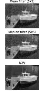
Finally, we tested Noise2Void on fluorescence microscopy data from the Cell Tracking Challenge. More specifically, we used the datasets Fluo-C2DL-MSC (CTC-MSC) and Fluo-N2DH-GOWT1 (CTC-N2DH). As before, no ground truth images or second noisy images are available. Hence, only BM3D and N2V training can be applied to this data.
In the last two rows of Figure 4, we compare our results to BM3D. In the absence of ground truth data, we can only judge the results visually. We find that the N2V trained network gives subjectively smooth and appealing result, while requiring only a fraction of the BM3D runtime.
\begin{overpic}[width=76.82234pt]{figs/limitation_rare_pixel/gt_limitation_pixel} \put(1.5,2.5){{\color[rgb]{1,1,1}\definecolor[named]{pgfstrokecolor}{rgb}{1,1,1}\pgfsys@color@gray@stroke{1}\pgfsys@color@gray@fill{1}{\small(a)}}} \put(62.4,12.5){\rotatebox{315.0}{{\color[rgb]{1,0,0}\definecolor[named]{pgfstrokecolor}{rgb}{1,0,0}{\small\bf\char 228}}}} \end{overpic} \begin{overpic}[width=76.82234pt]{figs/limitation_rare_pixel/care_limitation_pixel} \put(1.5,2.5){{\color[rgb]{1,1,1}\definecolor[named]{pgfstrokecolor}{rgb}{1,1,1}\pgfsys@color@gray@stroke{1}\pgfsys@color@gray@fill{1}{\small(b)}}} \put(62.4,12.5){\rotatebox{315.0}{{\color[rgb]{1,0,0}\definecolor[named]{pgfstrokecolor}{rgb}{1,0,0}{\small\bf\char 228}}}} \end{overpic} \begin{overpic}[width=76.82234pt]{figs/limitation_rare_pixel/n2v_limitation_pixel} \put(1.5,2.5){{\color[rgb]{1,1,1}\definecolor[named]{pgfstrokecolor}{rgb}{1,1,1}\pgfsys@color@gray@stroke{1}\pgfsys@color@gray@fill{1}{\small(c)}}} \put(62.4,12.5){\rotatebox{315.0}{{\color[rgb]{1,0,0}\definecolor[named]{pgfstrokecolor}{rgb}{1,0,0}{\small\bf\char 228}}}} \end{overpic}
\begin{overpic}[width=76.82234pt]{figs/limitation_rare_pixel/worst_psnr_rw_gt} \put(1.5,2.5){{\color[rgb]{1,1,1}\definecolor[named]{pgfstrokecolor}{rgb}{1,1,1}\pgfsys@color@gray@stroke{1}\pgfsys@color@gray@fill{1}{\small(d)}}} \end{overpic} \begin{overpic}[width=76.82234pt]{figs/limitation_rare_pixel/worst_psnr_rw_care} \put(1.5,2.5){{\color[rgb]{1,1,1}\definecolor[named]{pgfstrokecolor}{rgb}{1,1,1}\pgfsys@color@gray@stroke{1}\pgfsys@color@gray@fill{1}{\small(e)}}} \end{overpic} \begin{overpic}[width=76.82234pt]{figs/limitation_rare_pixel/worst_psnr_rw_n2v} \put(1.5,2.5){{\color[rgb]{1,1,1}\definecolor[named]{pgfstrokecolor}{rgb}{1,1,1}\pgfsys@color@gray@stroke{1}\pgfsys@color@gray@fill{1}{\small(f)}}} \end{overpic}
\begin{overpic}[width=76.82234pt]{figs/limitation_pattern/checker_input} \put(1.5,2.5){{\color[rgb]{1,1,1}\definecolor[named]{pgfstrokecolor}{rgb}{1,1,1}\pgfsys@color@gray@stroke{1}\pgfsys@color@gray@fill{1}{\small(a)}}} \end{overpic} \begin{overpic}[width=76.82234pt]{figs/limitation_pattern/checker_care_pred} \put(1.5,2.5){{\color[rgb]{1,1,1}\definecolor[named]{pgfstrokecolor}{rgb}{1,1,1}\pgfsys@color@gray@stroke{1}\pgfsys@color@gray@fill{1}{\small(b)}}} \end{overpic} \begin{overpic}[width=76.82234pt]{figs/limitation_pattern/checker_pred} \put(1.5,2.5){{\color[rgb]{1,1,1}\definecolor[named]{pgfstrokecolor}{rgb}{1,1,1}\pgfsys@color@gray@stroke{1}\pgfsys@color@gray@fill{1}{\small(c)}}} \end{overpic}
\begin{overpic}[width=76.82234pt]{figs/limitation_pattern/ctc_pattern_input} \put(1.5,2.5){{\color[rgb]{1,1,1}\definecolor[named]{pgfstrokecolor}{rgb}{1,1,1}\pgfsys@color@gray@stroke{1}\pgfsys@color@gray@fill{1}{\small(d)}}} \end{overpic} \begin{overpic}[width=76.82234pt]{figs/place_holder_white_frame} \put(29.0,42.0){\scalebox{4.0}{$\varnothing$}} \put(-2.0,24.0){\makebox[80.0pt]{\Centerstack{\scriptsize{Clean target}}}} \put(-2.0,14.0){\makebox[80.0pt]{\Centerstack{\scriptsize{not available.}}}} \end{overpic} \begin{overpic}[width=76.82234pt]{figs/limitation_pattern/ctc_pattern_denoised} \put(1.5,2.5){{\color[rgb]{1,1,1}\definecolor[named]{pgfstrokecolor}{rgb}{1,1,1}\pgfsys@color@gray@stroke{1}\pgfsys@color@gray@fill{1}{\small(e)}}} \end{overpic}
4.4 Errors and Limitations
We want to start this section by showing extreme error cases of N2V trained network predictions on real images (for which our training method performs least convincing). Figure 5 shows the ground truth image, and prediction results of traditionally trained and N2V trained networks. While the upper row contains the image with the largest squared single pixel error, the lower row shows the image with the largest sum of squared pixel errors.
We see these errors as an excellent illustration, showing a limitation of the N2V method. One of the underlying assumptions of N2V is the predictability of the signal (see Eq. 2). Both test images shown in Figure 5 include high irregularities, that are difficult to predict. The more difficult it is to predict a pixel’s signal from its surroundings the more errors are expected to appear in N2V predictions. This is of course true for traditional training and N2N as well. However, while these methods can utilize the value in the center pixel of the receptive field, this value is blocked for N2V.
In Figure 6, we illustrate another limitation of our method. N2V cannot distinguish between the signal and structured noise that violates the assumption of pixel-wise independence (see Eq. 3). We demonstrate this behaviour using artificially generated structured noise applied to an image. The N2V trained CNN removes the unpredictable components of the noise, but reveals the hidden pattern. Interestingly, we find the same phenomenon in real microscopy data from the Fluo-C2DL-MSC dataset. Denoising with a N2V trained CNN reveals a systematic error of the imaging system, visible as a striped pattern.
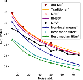
4.5 Performance over Various Noise Levels
We additionally ran our method and multiple baselines, including mean and median filters, as well as the classical non-local means [2], on the BSD68 dataset using various levels of noise. To find the optimal parameter for non-local means we performed a grid search. We also include a comparison to DnCNN using the numbers reported in [25]. All results can be found in Figure 7.
5 Conclusion
We have introduced Noise2Void, a novel training scheme that only requires single noisy acquisitions to train denoising CNNs. We have demonstrated the applicability of N2V on a variety of imaging modalities i.e. photography, fluorescence microscopy, and cryo-Transmission Electron Microscopy. As long as our initial assumptions of a predictable signal and pixel-wise independent noise are met, N2V trained networks can compete with traditionally and N2N trained networks. Additionally, we have analyzed the behaviour of N2V training when these assumptions are violated.
We believe that the Noise2Void training scheme, as we propose it here, will allow us to train powerful denoising networks. We have shown multiple examples how denoising networks can be trained on the same body of data which is to be processed in the first place. Hence, N2V training will open the doors to a plethora of applications, i.e. on biomedical image data.
Acknowledgements
We thank Uwe Schmidt, Martin Weigert, Alexander Dibrov, and Vladimir Ulman for the helpful discussions and for their assistance in data preparation. We thank Tobias Pietzsch for proof reading.
References
- [1] J. Batson and L. Royer. Noise2self: Blind denoising by self-supervision. arXiv preprint arXiv:1901.11365, 2019.
- [2] A. Buades, B. Coll, and J.-M. Morel. A non-local algorithm for image denoising. In CVPR, 2005.
- [3] T.-O. Buchholz, M. Jordan, G. Pigino, and F. Jug. Cryo-care: Content-aware image restoration for cryo-transmission electron microscopy data. arXiv preprint arXiv:1810.05420, 2018.
- [4] J. Chen, J. Chen, H. Chao, and M. Yang. Image blind denoising with generative adversarial network based noise modeling. In CVPR, pages 3155–3164, 2018.
- [5] K. Dabov, A. Foi, V. Katkovnik, and K. Egiazarian. Image denoising by sparse 3-d transform-domain collaborative filtering. IEEE Transactions on image processing, 16(8):2080–2095, 2007.
- [6] S. Guo, Z. Yan, K. Zhang, W. Zuo, and L. Zhang. Toward convolutional blind denoising of real photographs. arXiv preprint arXiv:1807.04686, 2018.
- [7] K. He, X. Zhang, S. Ren, and J. Sun. Deep residual learning for image recognition. In CVPR, pages 770–778, 2016.
- [8] S. Ioffe and C. Szegedy. Batch normalization: Accelerating deep network training by reducing internal covariate shift. arXiv preprint arXiv:1502.03167, 2015.
- [9] V. Jain and S. Seung. Natural image denoising with convolutional networks. In Advances in Neural Information Processing Systems, pages 769–776, 2009.
- [10] E. Knapek and J. Dubochet. Beam damage to organic material is considerably reduced in cryo-electron microscopy. Journal of molecular biology, 141(2):147–161, 1980.
- [11] S. Lefkimmiatis. Universal denoising networks: A novel cnn architecture for image denoising. In CVPR, pages 3204–3213, 2018.
- [12] J. Lehtinen, J. Munkberg, J. Hasselgren, S. Laine, T. Karras, M. Aittala, and T. Aila. Noise2Noise: Learning image restoration without clean data. In ICML, pages 2965–2974, 2018.
- [13] J. Long, E. Shelhamer, and T. Darrell. Fully convolutional networks for semantic segmentation. In CVPR, pages 3431–3440, 2015.
- [14] X. Mao, C. Shen, and Y.-B. Yang. Image restoration using very deep convolutional encoder-decoder networks with symmetric skip connections. In Advances in neural information processing systems, pages 2802–2810, 2016.
- [15] O. Ronneberger, P. Fischer, and T. Brox. U-net: Convolutional networks for biomedical image segmentation. In MICCAI, pages 234–241. Springer, 2015.
- [16] S. Roth and M. J. Black. Fields of experts: A framework for learning image priors. In CVPR, volume 2, pages 860–867. IEEE, 2005.
- [17] S. Roth and M. J. Black. Fields of experts. International Journal of Computer Vision, 82(2):205, 2009.
- [18] Y. Tai, J. Yang, X. Liu, and C. Xu. Memnet: A persistent memory network for image restoration. In CVPR, pages 4539–4547, 2017.
- [19] M. F. Tappen, C. Liu, E. H. Adelson, and W. T. Freeman. Learning gaussian conditional random fields for low-level vision. In CVPR, pages 1–8. IEEE, 2007.
- [20] V. Ulman, M. Maška, K. E. Magnusson, O. Ronneberger, C. Haubold, N. Harder, P. Matula, P. Matula, D. Svoboda, M. Radojevic, et al. An objective comparison of cell-tracking algorithms. Nature methods, 14(12):1141, 2017.
- [21] D. Ulyanov, A. Vedaldi, and V. S. Lempitsky. Deep image prior. CoRR, abs/1711.10925, 2017.
- [22] A. Van Den Oord, N. Kalchbrenner, and K. Kavukcuoglu. Pixel recurrent neural networks. In ICML, pages 1747–1756. JMLR.org, 2016.
- [23] M. Weigert, L. Royer, F. Jug, and G. Myers. Isotropic reconstruction of 3d fluorescence microscopy images using convolutional neural networks. In M. Descoteaux, L. Maier-Hein, A. Franz, P. Jannin, D. L. Collins, and S. Duchesne, editors, MICCAI, pages 126–134, Cham, 2017. Springer International Publishing.
- [24] M. Weigert, U. Schmidt, T. Boothe, A. Müller, A. Dibrov, A. Jain, B. Wilhelm, D. Schmidt, C. Broaddus, S. Culley, M. Rocha-Martins, F. Segovia-Miranda, C. Norden, R. Henriques, M. Zerial, M. Solimena, J. Rink, P. Tomancak, L. Royer, F. Jug, and E. W. Myers. Content-aware image restoration: Pushing the limits of fluorescence microscopy. Nature Methods, 2018.
- [25] K. Zhang, W. Zuo, Y. Chen, D. Meng, and L. Zhang. Beyond a gaussian denoiser: Residual learning of deep cnn for image denoising. IEEE Transactions on Image Processing, 26(7):3142–3155, 2017.
- [26] K. Zhang, W. Zuo, and L. Zhang. Ffdnet: Toward a fast and flexible solution for cnn based image denoising. IEEE Transactions on Image Processing, 2018.
- [27] M. Zontak and M. Irani. Internal statistics of a single natural image. In CVPR, pages 977–984. IEEE, 2011.