gbsn\CJKtilde\CJKnospace
On-chip chiral single-photon interface: Isolation and unidirectional emission
Abstract
Chiral quantum systems have received intensive attention in fundamental physics and applications in quantum information processing including optical isolation and photon unidirectional emission. Here, we design an on-chip emitter-resonator system with strong chiral light-matter interaction for a chiral single-photon interface. The system includes a microring resonator with a strong evanescent field and a near-unity optical chirality along both of the whole outside and inside walls, allowing a strong and chiral coupling of the Whispering-Gallery mode to a quantum emitter. By initializing a quantum dot in a specific spin ground state or shifting the transition energy with a polarization-selective optical Stark effect, we show a broadband optical isolation at the single-photon level over several G Hz . Furthermore, a quantum emitter chirally coupling to the microring resonator can emit single photons unidirectionally. Our protocol paves a way to realize multifunctional chiral single-photon interface in on-chip quantum information processing and quantum networks.
Optical chirality, non-reciprocity and unidirectional emission are of particular interest in the fundamental science Peng et al. (2016); Bahari et al. (2017); Harari et al. (2018); Tsakmakidis et al. (2017); Bandres et al. (2018); Rodríguez-Fortuño et al. (2013); Bliokh et al. (2015a); Ramezani (2014); Xia et al. (2018) and promise important applications in modern optical systems Shao et al. (2018) and quantum information processing Lodahl et al. (2017); Ramos et al. (2014); Mahmoodian et al. (2016); González-Tudela et al. (2015); Li et al. (2018). The recent progress in these fields has led to an emerging field called “chiral quantum optics” Lodahl et al. (2017); Sayrin et al. (2015); Scheucher et al. (2016); Söllner et al. (2015); Le Feber et al. (2015); Barik et al. (2018); Young et al. (2015); Ramezani et al. (2018); Coles et al. (2016, 2017); Xia et al. (2014); Zhang et al. (2018); Xia et al. (2018).
A strong chiral light-matter interaction is the basis of chiral quantum optics and achieved by coupling a quantum emitter (QE) with photon-spin dependent transitions to an electric (e-) field, transversely confined in a subwavelength space and consequently possessing the “spin-moment locking” (SML) at particular positions Lodahl et al. (2017); Bliokh et al. (2015b); Bliokh and Nori (2015); Scheucher et al. (2016); Solano et al. (2017); Aiello et al. (2015); Burresi et al. (2009); Coles et al. (2017); Shen et al. (2011); Arcari et al. (2014); Xia et al. (2014). Realizing chiral light-matter interaction require either the magnetic-field-induced Zeeman shift Söllner et al. (2015) or an asymmetric dipole moment Bliokh et al. (2015b); Metelmann and Clerk (2015); Xia et al. (2014). This letter will focus on proposing a novel chiral interface for single photons by initializing a QE in a special spin state or using the optical Stark control.
Although optical non-reciprocity has been well studied in various systems and using different scenarios Yu and Fan (2009); Peng et al. (2014); Chang et al. (2014); Hua et al. (2016); He et al. (2018); Cao et al. (2017); Metelmann and Clerk (2015); Wang et al. (2013); Horsley et al. (2013); Sounas and Alù (2017); He et al. (2016); Jia et al. (2018); Feng et al. (2011); Huang et al. (2018); Maayani et al. (2018); Ma et al. , optical isolation at the single-photon level has only been reported in quantum optical systems with chiral light-matter interaction, based on the photonic SML Scheucher et al. (2016); Sayrin et al. (2015); Söllner et al. (2015); Xia et al. (2014); Shomroni et al. (2014) or the photonic Aharonov-Bohm effect Yuan et al. (2015). The chiral-waveguide-based or chiral-cavity-based single-photon isolation normally has a narrow bandwidth, typically up to tens of Scheucher et al. (2016); Sayrin et al. (2015); Xia et al. (2014), limited to the edge of the band or the weak evanescent e-field due to a large transverse dimension Söllner et al. (2015); Young et al. (2015); Xia et al. (2014); Arcari et al. (2014); Scheucher et al. (2016); Sayrin et al. (2015); Sedlmeir et al. (2013). Additionally, the QE needs to be positioned precisely in a nanosize region. Moreover, unidirectional emission of single photons is highly desired but has only been demonstrated in a chiral waveguide-emitter system Barik et al. (2018); Söllner et al. (2015); Coles et al. (2016, 2017).
In this letter, we present a CMOS-compatible chiral photonic interface for single-photon isolation and unidirectional emission. In our design, the silicon microring resonator with a subwavelength transverse dimension has an exceptionally strong evanescent e-field and a unity optical chirality (OC) surrounding the whole outside and inside walls. Therefore, even the resonator with a moderate quality factor can strongly couples to a negatively charged quantum dot (QD) in a chiral way. In this, we can realize broadband single-photon isolation, and achieve unidirectional and polarization-deterministic single-photon emission.
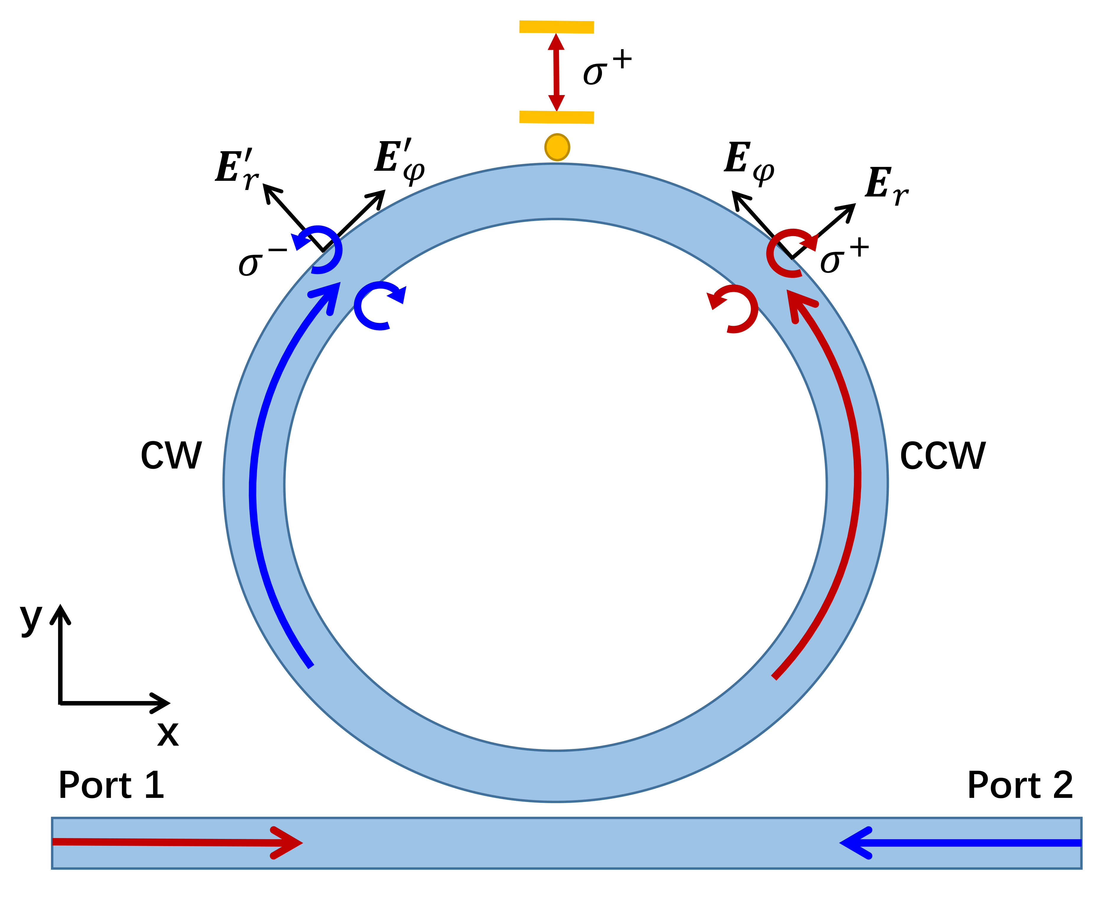
Our QD-resonator system, depicted in Fig. 1, consists of a silicon waveguide, a silicon microring resonator with the refractive index , and a single negatively charged QD. The resonator and the waveguide are µ m wide and µ m thick. The resonator has a µ m radius. Its Whispering-Gallery modes (WGMs) decays into the waveguide at a rate . Our numerical simulation with the finite-difference time-domain (FDTD) method yields an intrinsic quality factor of at the wavelength µ m , and a mode volume . The corresponding resonance frequency and the intrinsic decay rate are and , respectively, yielding a total decay rate of . A higher Q factor, e.g. at , has been experimentally demonstrated in a SOI mesoscopic resonator Xiao et al. (2007), even for a smaller mode volume Xu et al. (2008a). The relative low Q factor of our resonator is due to the large spatial grid in simulation, limited by available computation resource. The waveguide-resonator gap () is set to µ m that the critical coupling condition is almost obtained, confirmed by a vanishing transmission, , of an empty resonator Sup (a).
Now we design the microring resonator that the clockwise (CW) and counterclockwise (CCW) WGMs possess the SML. We numerically investigate the electric field distribution of these two modes. The input light from port or is almost exclusively transversally polarized, i.e. TE mode. Whereas the light circulating in the resonator is tightly confined in the transverse direction as a TM mode Kawalec et al. (2007); Junge et al. (2013); Shao et al. (2018). Thus, the evanescent e-field near the side surfaces of the resonator has a local longitudinal-polarizated component () and a transverse component (). These two components are out of phase with each other Kawalec et al. (2007), with the sign depending on the propagating direction of the light (see Fig. 1). The evanescent field of the WGM is inherently elliptically polarized with its polarization locked to the propagating direction. The complex-valued amplitude of the evanescent field is given by . The ratio can be estimated as Junge et al. (2013). In our design with and , the ratio is about . Thus, the evanescent fields are near perfectly circularly polarized, i.e. -polarized.
Next, we numerically evaluate the OC of our resonator by FDTD simulation. We first calculate the intensity difference between the left-circularly () and right-circularly () polarized components, , at the position with and , where and are unit vectors along the and directions, respectively. For a TE mode input from the port 1, the intensity difference distribution is shown in Fig. 2(a).
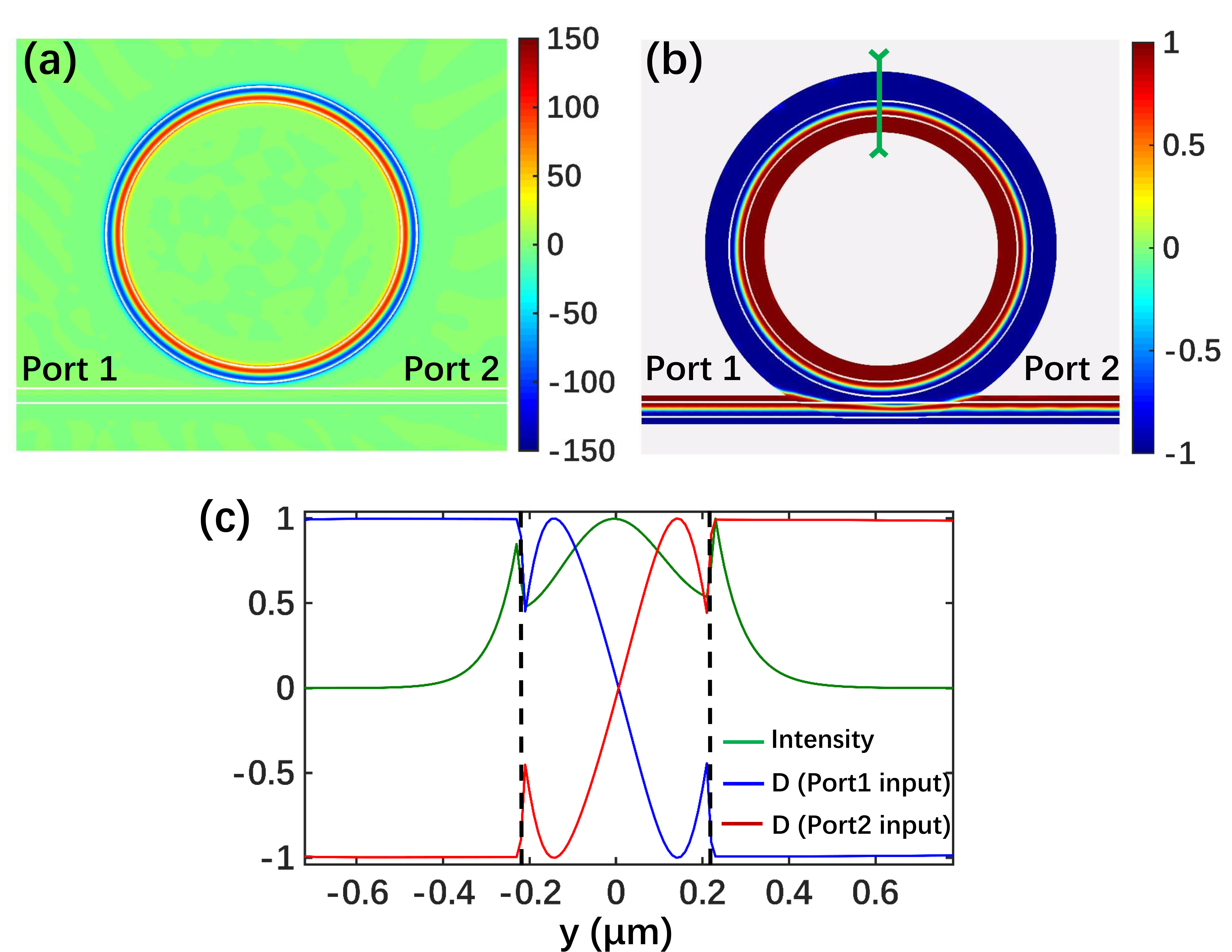
The evanescent e-field along the outside (inside) wall is almost - (-) polarized, while it is linearly-polarized in the middle of the resonator. The OC, defined as Vázquez-Lozano and Martínez (2018); Tang and Cohen (2010); Bliokh and Nori (2011); OCD , figures in what degree the field is locked to the light momentum. It is an important value showing the chirality of the field. The value implies the field is entirely - (-) polarized, while corresponds to a linear polarization. Clearly, our designed resonator has nearly unity OC along both the outside and inside walls, see Fig. 2(b). For example, when the light enters the waveguide from the port and excites the CCW mode, the outer (inner) evanescent e-field of the WGM is - (-) polarized, indicated by . More details of the fields and the OC are shown in Fig. 2(c) for the cross area marked by the green line in Fig. 2(b). In stark contrast to the linearly-polarized e-field at the middle of the resonator, the evanescent e-field is a nearly-perfect circular polarization for both cases of light incident to the port and port . When the light is reversed, the polarization also interchanges. We obtain from the surface of the outside wall to a position away in the radial direction. This large chiral area greatly relaxes the requirement for precisely positioning a QD. Importantly, the intensities of the evanescent fields near the walls are almost equal to that in the middle of the resonator. This feature of our design, in comparison with the conventional bottle-shaped resonator, allows a stronger coupling between a nearby QD and the resonator.
Now we go to describe the chiral and strong interaction between a QD and the resonator. As shown in Fig. 1, a negatively charged QD is positioned nearby the outside wall of the resonator. It has two energy-degenerate transitions at , driven by a circularly-polarized e-field. Note that the light at this wavelength is transparent in silicon. It can be an InAs self-assembled QD grown on the silicon-dioxide/silicon substrates Heitz et al. (1999); Choi et al. (2001); Benyoucef et al. (2013), with two electronic spin ground states, and, and two optically excited states, and . The notation () denotes the spin-up (spin-down) hole state, and () is for the spin-up (spin-down) electronic state. When the QD is prepared in the () state, it can only be driven by the - (-) polarized field to the state () in the absence of external magnetic field. Initialization of the QD in either ground state has been experimentally demonstrated with a near-unity probability Atatüre et al. (2006); Xu et al. (2007, 2008b). The polarization-selective transition, or , can also be tuned to have different energies via the optical Stark effect (OSE) Vora et al. (2015); Yong et al. (2018); Ye et al. (2017); Giovanni et al. (2016); Xia and Twamley (2013); Xia et al. (2012). For simplicity, we assume that the QD is completely populated in the spin up ground state, or only allows the polarized transition, enabled by the OSE. Thus, the QD can be treated as a two-level system with a driven transition, see Fig. 1. It only couples to the CCW WGM of the resonator. Note that the OSE-based method allows an all-optical operation. In fabrication, the QD can be engineered to have various resonance wavelengths, dipole moments and decoherence rates. Here, we assume that and a dipole moment , yielding a spontaneous emission rate Solano et al. (2017). Such parameters for the QD are experimentally available Htoon et al. (2002); Silverman et al. (2003); Javadi et al. (2018). The mode volume is calculated to be , yielding the QD-resonator coupling strength . Thus, we reach the strong coupling regime, , when .
In our design, the QD strongly couples to the CCW WGM but decouples from the counter-propagating CW WGM. Therefore, our quantum QD-resonator system is chiral and subsequently allows one to realize the single-photon isolation. Below we first investigate the single-photon isolation of our system with the single-photon scattering method, developed by Shen and FanShen and Fan (2009a, 2005). Then, we show the dynamic non-reciprocity with single photons input into the two ports simultaneously. We find the steady-state forward and backward transmission amplitudes, corresponding to the input to the port and port Sup (b); Shen and Fan (2009b, a, 2005); Xia et al. (2014), respectively,
| (1a) | ||||
| (1b) | ||||
where and ; is the external decay rate of the resonator due to the coupling to the waveguide; and is the group velocity of the photon in the waveguide. () is the coupling strength between the CCW (CW) WGM and the QD, models the intermode backscattering between the CCW and CW WGMs, typically due to the surface roughness. We define the detuning and always assume . The forward and backward transmissions are and , respectively. We have and .
The steady-state forward and backward transmissions for different detunings and OCs are shown in Fig. 3(a) and (b). For our special design, we have and , confirmed by the singlet peak at of the transmission of the bare resonator without the QD Sup (c). The performance of the single-photon isolation for is shown in Figs. 3(a). In the absence of the backscattering, i.e. , we obtain and at , corresponding to the insertion loss of and the isolation contrast Shen et al. (2011); Xia et al. (2014). Obviously, the single-photon isolation is achieved with almost zero insert loss and near-unity isolation contrast. Even for a relatively large backscattering , both the forward and backward transmissions only change very slightly, meaning a very small reduction in the performance. The nonreciprocal bandwidth is about , limited by the available QD-resonator coupling strength. To our best knowledge, this spectral window is about two-to-three orders broader than the previous achievements Sayrin et al. (2015); Scheucher et al. (2016); Söllner et al. (2015); Zhang et al. (2018); Xia et al. (2018). As seen from Fig. 3(b), the isolation contrast is quite robust, decreasing slowly from to as the OC decreases from to . While the insertion loss increases almost linearly during this region.
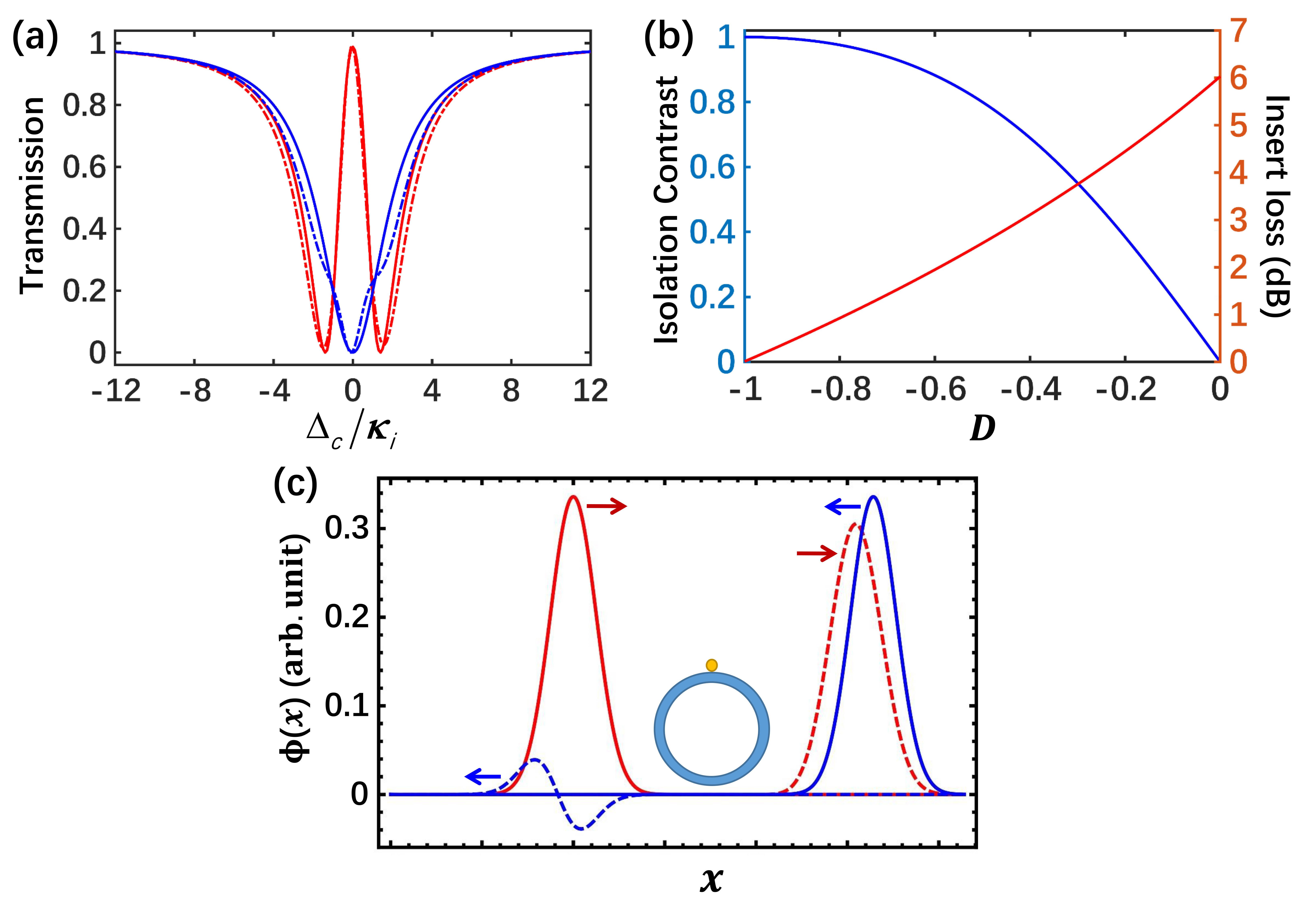
Many previous schemes for optical isolation suffer the dynamic reciprocity problem when oppositely propagating lights enter the system at the same time Shi et al. (2015). Our scheme can circumvent this challenging problem. To prove this point, we perform numerical simulations for the propagation of single-photon wave packets incident to the port and port simultaneously Sup (d); Shen and Fan (2009b, 2005), as shown in Fig. 3(c). We set the velocity of light in the waveguide , and apply the critical coupling condition. We apply Gaussian single-photon pulses with a bandwidth of . At resonance, the right-moving single-photon can pass through the system with a transmission . In contrast, the backward transmission probability of a left-moving single photon is only .
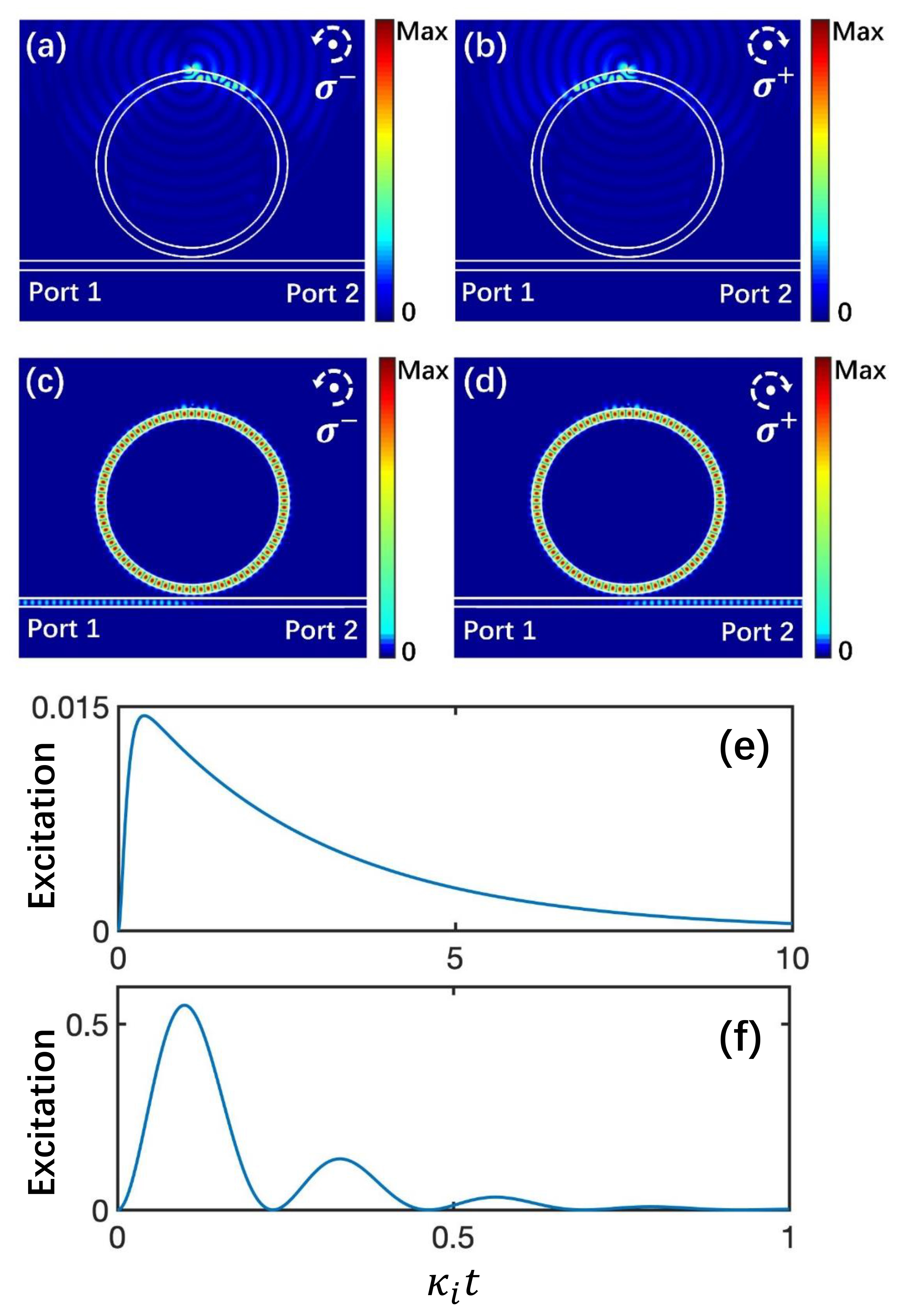
When the QD is initially prepared in its excited state, it will emit a single photon into either the CW resonator mode or the CCW one in the strong coupling regime. The exiting path of the photon is determined by the populated excited state of the QD. Therefore, by initializing the QD in a spin-selective excited state, we can realize the unidirectional emission of single photons with a deterministic polarization (an eigenmode of the waveguide). We are interested in the emission direction of photons. Thus, we replace the QD with a circularly-polarized Gaussian-pulse electric dipole, , in the FDTD simulation, where is the duration of the dipole-emitted photon pulse, and the delay. When the QD is prepared in the state corresponding to a -polarized dipole, it exclusively excites the CW mode, see Figs. 4 (a). The emitted single photon exits the system through the port , as shown in Figs. 4 (c). When the state is initially populated (given a -polarized dipole), the CCW mode is excited, and the single photon comes out from the port instead, see Figs. 4 (b) and (d). The dipole is on resonance with the WGM at and . We numerically solve the quantum Langevin equations for calculating the single-photon excitation collected by the waveguide Sup (e); Tan (1999). For a low-Q cavity with and , the emitted long-pulsed single photon is captured by the resonator and then is collected with an excitation of by the waveguide, see Fig. 4(e). Such unidirectional single-photon emission with a deterministic polarization (TE eigenmode of the waveguide) is important for scalable quantum computation but challenging He et al. . If the cavity intrinsic Q-factor can reach (already available experimentally Xiao et al. (2007)), a time-bin single photon, useful in quantum information technologies Brendel et al. (1999); Jayakumar et al. (2014), is obtained with a total excitation of [Fig. 4(f)].
Photon blockade can be achieved in a strongly-coupled QE-cavity system Shomroni et al. (2014); Dayan et al. (2008). A nonreciprocal version has only been proposed recently with a fast spinning resonator Huang et al. (2018). Because the QD strongly couples to the CCW GWM but decouples from the CW one, our solid-state device can also perform nonreciprocal photon blockade without moving parts.
In conclusion, we have proposed a chiral single-photon interface with a QD-resonator system. The evanescent e-field of the resonator is strong and perfectly circularly-polarized along the whole side surfaces. Thus, the resulting strong light-matter interaction with a near-unity OC can be achieved without the requirement of precisely positioning the QD as the previous works. We further show a G Hz -bandwidth single-photon isolator and controllable unidirectional emission of single photons. Our protocol can be extended to a chiral quantum system consisting of a subwavelength resonator interacting with 2D material or perovskites, prepared and operating at room temperature Ye et al. (2017); Giovanni et al. (2016); Yong et al. (2018); Gong et al. (2018); Schaibley et al. (2016); Odenthal et al. (2017). It provides an on-chip platform for a multifunctional single-photon interface.
The authors thank H.-D. Wu, Y.-G. Liu, Dr. T. Li for helpful discussions. H.Z., Y.Z., K.X. and M.X. thank the support of the National Key R&D Program of China (Grant No. 2017YFA0303703). This work is also supported by the National Natural Science Foundation of China (Grant Nos. 11874212, 11574145).
References
- Peng et al. (2016) B. Peng, Ş. K. Özdemir, M. Liertzer, W. Chen, J. Kramer, H. Yılmaz, J. Wiersig, S. Rotter, and L. Yang, Proc. Natl. Acad. Sci. U.S.A 113, 6845 (2016).
- Bahari et al. (2017) B. Bahari, A. Ndao, F. Vallini, A. E. Amili, Y. Fainman, and B. Kanté, Science 358, 636 (2017).
- Harari et al. (2018) G. Harari, M. A. Bandres, Y. Lumer, M. C. Rechtsman, Y. Chong, M. Khajavikhan, D. N. Christodoulides, and M. Segev, Science 359, eaar4003 (2018).
- Tsakmakidis et al. (2017) K. L. Tsakmakidis, L. Shen, S. A. Schulz, X. Zheng, J. Upham, X. Deng, H. Altug, A. F. Vakakis, and R. W. Boyd, Science 356, 1260 (2017).
- Bandres et al. (2018) M. A. Bandres, S. Wittek, G. Harari, M. Parto, J. Ren, M.Segev, D. N. Christodoulides, and M. Khajavikhan, Science 359, 1231 (2018).
- Rodríguez-Fortuño et al. (2013) F. J. Rodríguez-Fortuño, G. Marino, P. Ginzburg, D. O’Connor, A. Martínez, G. A. Wurtz, and A. V. Zayats, Science 340, 328 (2013).
- Bliokh et al. (2015a) K. Y. Bliokh, F. J. Rodríguez-Fortuño, F. Nori, and A. V. Zayats, Nat. Photonics 9, 796 (2015a).
- Ramezani (2014) H. Ramezani, Phys. Rev. Lett. 112, 043904 (2014).
- Xia et al. (2018) K. Xia, F. Nori, and M. Xiao, Phys. Rev. Lett. 121, 203602 (2018).
- Shao et al. (2018) Z. Shao, J. Zhu, Y. Chen, Y. Zhang, and S. Yu, Nat. Commun. 9, 926 (2018).
- Lodahl et al. (2017) P. Lodahl, S. Mahmoodian, S. Stobbe, A. Rauschenbeutel, P. Schneeweiss, J. Volz, H. Pichler, and P. Zoller, Nature (London) 541, 473 (2017).
- Ramos et al. (2014) T. Ramos, H. Pichler, A. J. Daley, and P. Zoller, Phys. Rev. Lett. 113, 237203 (2014).
- Mahmoodian et al. (2016) S. Mahmoodian, P. Lodahl, and A. S. Sørensen, Phys. Rev. Lett. 117, 240501 (2016).
- González-Tudela et al. (2015) A. González-Tudela, V. Paulisch, D. Chang, H. J. Kimble, and J. I. Cirac, Phys. Rev. Lett. 115, 163603 (2015).
- Li et al. (2018) T. Li, A. Miranowicz, X. Hu, K. Xia, and F. Nori, Phys. Rev. A 97, 062318 (2018).
- Sayrin et al. (2015) C. Sayrin, C. Junge, R. Mitsch, B. Albrecht, D. O’Shea, P. Schneeweiss, J. Volz, and A. Rauschenbeutel, Phys. Rev. X 5, 041036 (2015).
- Scheucher et al. (2016) M. Scheucher, A. Hilico, E. Will, J. Volz, and A. Rauschenbeutel, Science 354, 1577 (2016).
- Söllner et al. (2015) I. Söllner, S. Mahmoodian, S. L. Hansen, L. Midolo, A. Javadi, G. Kiršanskė, T. Pregnolato, H. El-Ella, E. H. Lee, and J. D. Song, Nat. Nanotechnol. 10, 775 (2015).
- Le Feber et al. (2015) B. Le Feber, N. Rotenberg, and L. Kuipers, Nat. Commun. 6, 096602 (2015).
- Barik et al. (2018) S. Barik, A. Karasahin, C. Flower, T. Cai, H. Miyake, W. DeGottardi, M. Hafezi, and E. Waks, Science 359, 666 (2018).
- Young et al. (2015) A. B. Young, A. C. T. Thijssen, D. M. Beggs, P. Androvitsaneas, L. Kuipers, J. G. Rarity, S. Hughes, and R. Oulton, Phys. Rev. Lett. 115, 153901 (2015).
- Ramezani et al. (2018) H. Ramezani, P. K. Jha, Y. Wang, and X. Zhang, Phys. Rev. Lett. 120, 043901 (2018).
- Coles et al. (2016) R. J. Coles, D. M. Price, J. E. Dixon, B. Royall, E. Clarke, P. Kok, M. S. Skolnick, Am Fox, and M. N. Makhonin, Nat. Commun. 7, 11183 (2016).
- Coles et al. (2017) R. J. Coles, D. M. Price, B. Royall, E. Clarke, M. S. Skolnick, A. M. Fox, and M. Makhonin, Phys. Rev. B 95, 121401 (2017).
- Xia et al. (2014) K. Xia, G. Lu, G. Lin, Y. Cheng, Y. Niu, S. Gong, and J. Twamley, Phys. Rev. A 90, 043802 (2014).
- Zhang et al. (2018) S. Zhang, Y. Hu, G. Lin, Y. Niu, K. Xia, J. Gong, and S. Gong, Nat. Photonics 12, 744 (2018).
- Bliokh et al. (2015b) K. Y. Bliokh, D. Smirnova, and F. Nori, Science 348, 1448 (2015b).
- Bliokh and Nori (2015) K. Y. Bliokh and F. Nori, Phys. Rep. 592, 1 (2015).
- Solano et al. (2017) P. Solano, J. A. Grover, J. E. Hoffman, S. Ravets, F. K. Fatemi, L. A. Orozco, and S. L. Rolston, Adv. At. Mol. Opt. Phys. 66, 439 (2017).
- Aiello et al. (2015) A. Aiello, P. Banzer, M. Neugebauer, and G. Leuchs, Nat. Photonics 9, 789 (2015).
- Burresi et al. (2009) M. Burresi, R. J. P. Engelen, A. Opheij, D. van Oosten, D. Mori, T. Baba, and L. Kuipers, Phys. Rev. Lett. 102, 033902 (2009).
- Shen et al. (2011) Y. Shen, M. Bradford, and J.-T. Shen, Phys. Rev. Lett. 107, 173902 (2011).
- Arcari et al. (2014) M. Arcari, I. Söllner, A. Javadi, S. L. Hansen, S. Mahmoodian, J. Liu, H. Thyrrestrup, E. H. Lee, J. D. Song, S. Stobbe, and P. Lodahl, Phys. Rev. Lett. 113, 093603 (2014).
- Metelmann and Clerk (2015) A. Metelmann and A. A. Clerk, Phys. Rev. X 5, 021025 (2015).
- Yu and Fan (2009) Z. Yu and S. Fan, Nat. Photonics 3, 91 (2009).
- Peng et al. (2014) B. Peng, Ş. K. Özdemir, F. Lei, F. Monifi, M. Gianfreda, G. L. Long, S. Fan, F. Nori, C. M. Bender, and L. Yang, Nat. Phys. 10, 394 (2014).
- Chang et al. (2014) L. Chang, X. Jiang, S. Hua, C. Yang, J. Wen, L. Jiang, G. Li, G. Wang, and M. Xiao, Nat. Photonics 8, 524 (2014).
- Hua et al. (2016) S. Hua, J. Wen, X. Jiang, Q. Hua, L. Jiang, and M. Xiao, Nat. Commun. 7, 13657 (2016).
- He et al. (2018) B. He, L. Yang, X. Jiang, and M. Xiao, Phys. Rev. Lett. 120, 203904 (2018).
- Cao et al. (2017) Q.-T. Cao, H. Wang, C.-H. Dong, H. Jing, R.-S. Liu, X. Chen, L. Ge, Q. Gong, and Y.-F. Xiao, Phys. Rev. Lett. 118, 033901 (2017).
- Wang et al. (2013) D.-W. Wang, H.-T. Zhou, M.-J. Guo, J.-X. Zhang, J. Evers, and S. Y. Zhu, Phys. Rev. Lett. 110, 093901 (2013).
- Horsley et al. (2013) S. A. R. Horsley, J.-H. Wu, and M. A. an G. C. La Rocca, Phys. Rev. Lett. 110, 223602 (2013).
- Sounas and Alù (2017) D. L. Sounas and A. Alù, Nat. Photonics 11, 774 (2017).
- He et al. (2016) C. He, X.-C. Sun, X.-P. Liu, M.-H. Lu, Y. Chen, L. Feng, and Y.-F. Chen, Proc. Natl. Acad. Sci. U.S.A 113, 4924 (2016).
- Jia et al. (2018) N. Jia, N. Schine, A. Georgakopoulos, A. Ryou, A. Sommer, and J. Simon, Phys. Rev. A 97, 013802 (2018).
- Feng et al. (2011) L. Feng, M. Ayache, J. Huang, Y.-L. Xu, M.-H. Lu, Y.-F. Chen, Y. Fainman, and A. Scherer, Science 333, 729 (2011).
- Huang et al. (2018) R. Huang, A. Miranowicz, J.-Q. Liao, F. Nori, and H. Jing, Phys. Rev. Lett. 121, 153601 (2018).
- Maayani et al. (2018) S. Maayani, R. Dahan, Y. Kligerman, E. Moses, A. U. Hassan, H. Jing, F. Nori, D. N. Christodoulides, and T. Carmon, Nature (London) 558, 569 (2018).
- (49) J. Ma, J. Wen, Y. Hu, S. Ding, X. Jiang, L. Jiang, and M. Xiao, arXiv:1806.03169 .
- Shomroni et al. (2014) I. Shomroni, S. Resenblum, Y. Lovsky, O. Bechler, G. Guendelman, and B. Dayan, Science 345, 903 (2014).
- Yuan et al. (2015) L. Yuan, S. Xu, and S. Fan, Opt. Lett. 40, 5140 (2015).
- Sedlmeir et al. (2013) F. Sedlmeir, M. Hauer, J. U. Fürst, G. Leuchs, and H. G. L. Schwefel, Opt. Express 21, 23942 (2013).
- Xiao et al. (2007) S. Xiao, M. H. Khan, H. Shen, and M. Qi, Opt. Express 15, 10553 (2007).
- Xu et al. (2008a) Q. Xu, D. Fattal, and R. G. Beausoleil, Opt. Express 16, 4309 (2008a).
- Sup (a) See Supplemental Material for the numerical simulation of the resonator .
- Kawalec et al. (2007) T. Kawalec, L. Józefowski, J. Fiutowski, M. J. Kasprowicz, and T. Dohnalik, Opt. Commun. 274, 341 (2007).
- Junge et al. (2013) C. Junge, D. O’Shea, J. Volz, and A. Rauschenbeutel, Phys. Rev. Lett. 110, 213604 (2013).
- Vázquez-Lozano and Martínez (2018) J. E. Vázquez-Lozano and A. Martínez, Phys. Rev. Lett. 121, 043901 (2018).
- Tang and Cohen (2010) Y. Tang and A. E. Cohen, Phys. Rev. Lett. 104, 163901 (2010).
- Bliokh and Nori (2011) K. Y. Bliokh and F. Nori, Phys. Rev. A 83, 021803 (2011).
- (61) To limit the optical chirality to a region from to , which can present a clearer picture to readers, here we normalize the conventional optical chirality with the local energy density .
- Heitz et al. (1999) R. Heitz, N. N. Ledentsov, D. Bimberg, A. Y. Egorov, M. V. Maximov, V. M. Ustinov, A. E. Zhukov, Z. I. Alferov, G. E. Cirlin, and I. P. Soshnikov, Appl. Phys. Lett. 74, 1701 (1999).
- Choi et al. (2001) B. H. Choi, C. M. Park, S.-H. Song, M. H. Son, S. W. Hwang, D. Ahn, and E. K. Kim, Appl. Phys. Lett. 78, 1403 (2001).
- Benyoucef et al. (2013) M. Benyoucef, M. Yacob, J. Reithmaier, J. Kettler, and P. Michler, Appl. Phys. Lett. 103, 162101 (2013).
- Atatüre et al. (2006) M. Atatüre, J. Dreiser, A. Badolato, A. Högele, K. Karrai, and A. Imamoglu, Science 312, 551 (2006).
- Xu et al. (2007) X. Xu, Y. Wu, B. Sun, Q. Huang, J. Cheng, D. G. Steel, A. S. Bracker, D. Gammon, C. Emary, and L. J. Sham, Phys. Rev. Lett. 99, 097401 (2007).
- Xu et al. (2008b) X. Xu, B. Sun, P. R. Berman, D. G. Steel, A. S. Bracker, D. Gammon, and L. J. Sham, Nat. Phys. 4, 692 (2008b).
- Vora et al. (2015) P. M. Vora, A. S. Bracker, S. G. Carter, T. M. Sweeney, M. Kim, C. S. Kim, L. Yang, P. G. Brereton, S. E. Economou, and D. Gammon, Nat. Commun. 6, 7665 (2015).
- Yong et al. (2018) C.-K. Yong, J. Horng, Y. Shen, H. Cai, A. Wang, C.-S. Yang, C.-K. Lin, S. Zhao, K. Watanabe, T. Taniguchi, S. Tongay, and F. Wang, Nat. Phys. 14, 1092 (2018).
- Ye et al. (2017) Z. Ye, D. Sun, and T. F. Heinz, Nat. Phys. 13, 26 (2017).
- Giovanni et al. (2016) D. Giovanni, W. K. Chong, H. A. Dewi, K. Thirumal, I. Neogi, R. Ramesh, S. Mhaisalkar, N. Mathews, and T. C. Sum, Sci. Adv. 2, e1600477 (2016).
- Xia and Twamley (2013) K. Xia and J. Twamley, Phys. Rev. X 3, 031013 (2013).
- Xia et al. (2012) K. Xia, G. K. Brennen, D. Ellinas, and J. Twamley, Opt. Express 20, 27198 (2012).
- Htoon et al. (2002) H. Htoon, T. Takagahara, D. Kulik, O. Baklenov, A. L. Holmes Jr, and C. K. Shih, Phys. Rev. Lett. 88, 087401 (2002).
- Silverman et al. (2003) K. L. Silverman, R. P. Mirin, S. T. Cundiff, and A. G. Norman, Appl. Phys. Lett. 82, 4552 (2003).
- Javadi et al. (2018) A. Javadi, D. Ding, M. H. Appel, S. Mahmoodian, M. C. Löbl, I. Söllner, R. Schott, C. Papon, T. Pregnolato, S. Stobbe, L. Midolo, T. Schröder, A. D. Wieck, A. Ludwig, R. J. Warburton, and P. Lodahl, Nat. Nanotechnol. 13, 398 (2018).
- Shen and Fan (2009a) J.-T. Shen and S. Fan, Phys. Rev. A 79, 023838 (2009a).
- Shen and Fan (2005) J.-T. Shen and S. Fan, Opt. Lett. 30, 2001 (2005).
- Sup (b) See Supplemental Material for the steady-state single-photon transport .
- Shen and Fan (2009b) J.-T. Shen and S. Fan, Phys. Rev. A 79, 023837 (2009b).
- Sup (c) See Supplemental Material for the transmission of the bare resonator .
- Shi et al. (2015) Y. Shi, Z. Yu, and S. Fan, Nat. Photonics 9, 388 (2015).
- Sup (d) See Supplemental Material for the K-space simulation of the time evolution of the single-photon wave packets .
- Sup (e) See Supplemental Material for the single-photon emission simulation with the quantum toolbox, which includes Ref. [85] .
- Tan (1999) S. M. Tan, J. Opt. B: Quantum Semiclass. Opt. 1, 424 (1999).
- (86) Y.-M. He, H. Wang, S. Gerhardt, K. Winkler, J. Jurkat, Y. Yu, M.-C. Chen, X. Ding, S. Chen, J. Qian, Z.-C. Duan, J.-P. Li, L.-J. Wang, Y.-H. Huo, S. Yu, S. Höfling, C.-Y. Lu, and J.-W. Pan, arXiv: 1809.10992 .
- Brendel et al. (1999) J. Brendel, N. Gisin, W. Tittel, and H. Zbinden, Phys. Rev. Lett. 82, 2594 (1999).
- Jayakumar et al. (2014) H. Jayakumar, A. Predojević, T. Kauten, T. Huber, G. S. Solomon, and G. Weihs, Nature Commun. 5, 4251 (2014).
- Dayan et al. (2008) B. Dayan, A. S. Parkins, T. Aoki, E. P. Ostby, K. J. Vahala, and H. J. Kimble, Science 319, 1062 (2008).
- Gong et al. (2018) S.-H. Gong, F. Alpeggiani, B. Sciacca, E. C. Garnett, and L. Kuipers, Science 359, 443 (2018).
- Schaibley et al. (2016) J. R. Schaibley, H. Yu, G. Clark, P. Rivera, J. S. Ross, K. L. Seyler, W. Yao, and X. Xu, Nat. Rev. Mater. 1, 16055 (2016).
- Odenthal et al. (2017) P. Odenthal, W. Talmadge, N. Gundlach, R. Wang, C. Zhang, D. Sun, Z.-G. Yu, Z. V. Vardeny, and Y. S. Li, Nat. Phys. 13, 894 (2017).