High speed imaging of solid needle and liquid micro-jet injections
Abstract
High speed imaging was used to capture the fast dynamics of two injection methods. The first one and perhaps the oldest known, is based on solid needles and used for dermal pigmentation, or tattooing. The second, is a novel needle-free micro-jet injector based on thermocavitation. We performed injections in agarose gel skin surrogates, and studied both methods using ink formulations with different fluidic properties to understand better the end-point injection. Both methods were used to inject water and a glycerin-water mixture. Commercial inks were used with the tattoo machine and compared with the other liquids injected. The agarose gel was kept stationary or in motion at a constant speed, along a plane perpendicular to the needle. The agarose deformation process due to the solid needle injection was also studied. The advantages and limitations of both methods are discussed, and we conclude that micro-jet injection has better performance than solid injection when comparing several quantities for three different liquids, such as the energy and volumetric delivery efficiencies per injection, depth and width of penetrations. A newly defined dimensionless quantity, the penetration strength, is used to indicate potential excessive damage to skin surrogates. Needle-free methods, such as the micro-jet injector here presented, could reduce the environmental impact of used needles, and benefit the health of millions of people that use needles on a daily basis for medical and cosmetic use.
I Introduction
Tattooing, also known as dermal pigmentation, is done by inserting exogenous substances such as pigments into the dermis and leaving a permanent mark sperry1991tattoos ; kluger2012tattoos ; islam2016medical . The earliest evidence of tattooing procedures traces back to the fourth millennium BCE friedman2018natural . As evidenced by mummified skin, ancient art, and the archaeological records, tattoos have served two basic functions: medicinal or cosmetic tattohealth . Two distinctive types of cosmetic tattoos exist; the conventional or purely decorative, and those intended to alleviate existing conditions and are defined as permanent make-up, e.g. scar camouflaging, alopecia or post-mastectomy pigmentation of a nipple on cancer patients.
The societal acceptance of tattoos has varied over the years, however, there is a recent worldwide increase in its numbers and the social groups having tattoos or permanent make-up. According to a recent report, 12% of the European population has one or more tattoos eurreport . This corresponds to more than 44 million tattooed europeans, while the figures in USA and other countries is supposed to be similar or higher. This means that our society as a whole will be posed with scientific and technological challenges to reduce health risks caused by tattooing, and palliate its economic consequences.
Despite the advances made in electronics and improved hygienic conditions, the basic injection process has not changed much. According to experts, depending on the skin type and individual, a tattoo can be painful, cause skin related allergies, while 20-50% of the ink is not injected Petersen2016 . The method used for tattooing and permanent make-up is in principle the same: the repeated injection of one or several needles into the skin delivers ink droplets through the open wounds. The ink that adheres to the needle surface is transported into the dermis of the skin, as a function of the angle of the needle with respect to the skin, and the pressure applied by the tattoo artist or the cosmetic technician. Solid needles with single or multiple tips are typically sold as single-use consumables. The formulation of inks is kept as a secret by commercial brands, but their ingredients can be roughly categorised according to its function. Inks are composed of different pigments suspended in a carrier solution, together with binders and additiveseurreport . Each ink formulation has different ingredient proportions, conferring tailored fluid dynamic properties, such as viscosity, surface tension and density jang2009influence ; Petersen2016 . Pigments are inorganic particles responsible for the ink colour tone, with a particle size range of 0.1 m - 50 m. The larger the particle, the least they can be processed and removed by the immunological system of the human body, which in turn guarantees the permanence of the tattoo Grant2015 .
Less known is the fact that tattoo machines have been adapted for intradermal injections to evenly inject into a large area of the skin, dividing effectively the dose in smaller portions Kim2017 . During the last decades, alternative cutaneous delivery methods have been developed, including transdermal delivery injections at high pressures TABERNER and needle-assisted jet injectors LI2016195 . A liquid jet injector is a needle-free medical device that pressurises thin liquid filaments to penetrate the skin, with clear advantages over conventional injections with needles Mitragotri:2006jd ; Kim2017 ; Arora2017 ; munch2017dermal . Jet injectors have helped in smallpox eradication, preventing rabies, influenza, malaria, hepatitis A and B, injecting insulin and analgesics, etc BAXTER2005361 ; schramm2002transdermal ; Gwen2017 ; Kim2017 ; Arora2017 ; munch2017dermal . Some proven advantages are higher immunological response, drug dose sparing, reduction in pain with improved patient compliance, and reduction of accidental needle-stick incidents hogan2015needle .
To the best of our knowledge, a rigorous description of the tattooing process –one of the oldest transdermal injection methods– is presented for the first time. A comparison with a novel micro-jet injector device –a needle-free injection method carla – is performed on the basis of quantification of different observables.
II Experimental setup and procedure
II.1 Solid needle injector
A solid needle injector was vertically fixed in order to inject liquid into a skin surrogate made of agarose gel, as shown in figure 1 (a). The solid needle injector is a conventional pigmentation instrument (PL-1000 Mobil, Permanent Line GmbH). It is composed of an electric control unit, a hand piece, and a consumable hygiene needle module. The hand piece works with an encased motor that moves the attached needle up and down in a smooth, cyclical pattern machines . The electric control unit enables an adjustable injection frequency, with nominal frequency values in the Hz range. The needle nozzle consists of a disposable single-use module attachable to the hand piece, which contains a sterilised solid needle, made from stainless-steel. Needles with a diameter of =4 mm were used for this study.
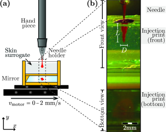
The agarose gel samples were placed inside a custom-made holder, and the holder was located under the hand piece with the surface of the gel almost touching the needle tip, as shown in figure 1 (a) and (b). The gel is confined by glass transparent walls providing a depth (-axis), width (-axis) and length (-axis) of 3 mm, 3 mm and 20 mm, respectively. A mirror with a 45∘ orientation is placed below the gel. This system allows the simultaneous frontal and bottom visualisation of the injection processes into the gels. The holder is attached to a one-axis motorized translation stage (MT1/M-Z8, Thorlabs) which allows to keep the gel stationary or in motion at a constant speed mm/s, along a plane perpendicular to the needle.
Front view images were obtained using a color high-speed camera (Fastcam SA2, Photron) capturing 1000 frames per second; an example of the images acquired is shown in figure 1 (b). In addition, the agarose gel deformation was measured with dry needles–without ink–, using a monochromatic high-speed camera (Fastcam SA-X2, Photron) recording at 10000 frames per second, and with a high-spatial resolution of 1409 pixels per millimeter.
(i) Characterization of the needle displacement:
In order to characterize the needle vertical displacement, we used the high-speed camera varying the nominal frequency from 50 to 150 Hz. The videos were recorded at 10000 frames per second, with a spatial resolution of 300 pixels per millimeter.
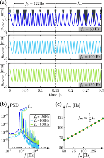
The tip position is obtained and plotted with respect to time, as shown in figure 2 (a). During the first seconds, the needle vertical displacement is the same for every nominal frequency. A slow oscillation is followed by a cyclical displacement with constant frequency Hz and measured amplitude mm. After this time, s, the measured frequency reach an stable value directly correlated to . In figure 2 (b), we plot the power spectral density of at s for the 3 cases shown in figure 2 (a), the position of the first peak corresponds to the measured frequency . In figure 2 (c), we plot versus for all the experiments giving a linear relation .
(ii) Injection force measurement:
In order to measure the force exerted by the solid needle injector into the agarose, we performed a separate experiment where the injector and skin surrogate setup were placed on a precision balance (Denver Instrument, APX-1000, =0.1 mg), as shown in figure 3 (a). The injector is switched on applying a normal force on the agarose which is recorded by the balance, indicating the measured effective mass . The force and the effective mass are related by the equation
| (1) |
where is the magnitude of the gravitational acceleration.
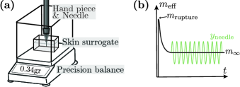
When the solid needle starts to move, an initial peak mass is measured. This mass corresponds to the moment when the agarose gel is ruptured, i.e. when the needle penetrates into the gel. After that, the measured mass reaches a stable value , corresponding to the average effective mass due to the the oscillatory movement of the needle .
We have measured an effective mass gr and gr, for an agarose gel of 1%wt and needle displacement frequency Hz ( Hz), which corresponds to an applied normal force: .
II.2 Needle-free micro-jet injector
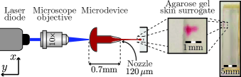
A continuous wave CW laser diode was focused at the bottom surface of a glass microfluidic device, which was partially filled with aqueous solutions of a molecular dye matching the laser wavelength. The liquid heats up above its boiling point in a few microseconds with an explosive phase transition resulting in a fast growing vapour bubble inside the microdevice; this phenomenon is known as thermocavitation rastopov1991sound ; Padilla-Martinez2014 . The bubble pushes the liquid forming a jet which in turn can penetrate into an agarose gel located in front, as shown in figure 4. The microfluidic devices used were similar to those described elsewhere berrospe2016continuous ; carla .
Microfluidic devices were designed and fabricated in glass substrates under cleanroom conditions. Each device has a fluidic chamber in which bubbles are created, and is connected to a tapered channel with a 120 m diameter nozzle. For further details on this setup, the reader is referred to Berrospe et al. carla
The laser diode, with a wavelength nm is focused at the bottom of the device with a 10 microscope objective. The spot has an elliptical shape, with beam diameters m and m and variable power P = 400-600 mW. The transparent glass walls of a custom-made agarose holder permits the visualization of injection processes, as shown in the inset of figure 4. The agarose depth (-axis), width (-axis) and length (-axis) are fixed at 5 mm, 3 mm and 24 mm, respectively.
The bubble growth, the liquid jet formation and the penetration into agarose slabs were recorded at frames per second using a ultrahigh-speed camera (Phantom v2640). The camera sensor is protected from the laser light using a colored glass filter centered at nm.
II.3 Liquid inks description
Three different liquid inks were used on the experiments: commercially available Permanent make-up (PMU) inks, red dyed water and red dyed glycerin-water mixture at 10%wt. By adding glycerin, the injection process, i.e. the adhesion to the needle tip and the diffusion in the agarose, is modified with respect to pure water. In order to maximize the absorbed energy by the liquid from the focused laser, in the needle-free micro-jet injector, the aqueous solutions are coloured using a red dye (Direct Red 81, CAS No. 2610-11-9) diluted at 0.5 %wt.
The PMU inks are colloidal dispersions with flow-dependent viscoelastic properties. They are composed mainly by water and glycerol, and extra additives such as surfactants, solvents, binders and fillers wijshoff2010dynamics ; grande2016direct . Pigments provide colour and due to insolubility in water, guarantee the permanent character of the injected ink. Additives are used in order to avoid pigment sedimentation while storage and help the re-dispersion of the fluid after it is used. Microbiological contamination is common in tattoos due to the high content of water an organic substances present on inks. In order to avoid the contamination, preservatives are added to the mixture. Other impurities that can be found on tattoos are primary aromatic amines (PAA) and polycyclic aromatic hydrocarbons (PAH) eurreport ; Petersen2016 . In this study, we use two organic PMU inks: PMU-black (Amiea, Organic line, Deep Black, MT. Derm) and PMU-red (Amiea, Organic line, Cranberry, MT. Derm).
We performed rheology measurements of the liquid inks. Specifically, we have measured the viscosity varying the shear rate using a rheometer (Anton Paar MCR502) with a cone-plate geometry (with diameter mm and cone angle ). As shown in figure 5, the red colored water and the glycerin-water mixture behave as Newtonian fluids with measured constant viscosity mPas and mPas. On the contrary, the PMU inks show a shear thinning behaviour, i.e. the viscosity of the fluid decreases when the applied shear rate increases. The measured viscosity at high shear rates, s-1, for the PMU-black and PMU-red inks are mPas and mPas, respectively.
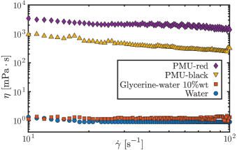
The larger viscosity value of PMU inks is provided by the high concentration of pigment particles, and other additives not present in the colored water, and water-glycerin solutions. PMU inks were not used on the needle-free micro-jet injector due to visualisation limitations caused by the light absorption of the pigments that impeded the observation of thermocavitation.
II.4 Agarose gel skin surrogate preparation
Among the skin surrogates widely used to simulate the mechanical properties of soft tissues, agarose is one of the most used due to its transparency which allows the optical quantification of injections kendall2002delivery ; deng2012preparation ; schramm2004jet ; williams2016jet ; carla ; Tagawa2 . The surrogates were prepared by diluting agarose powder (OmniPur agarose, CAS No. 9012-36-6.), in deionised water, with an agarose concentration of 1%wt. The solution was heated up 45 seconds in microwave at full power. Once the phantoms were prepared, they were cooled down at room temperature for 5 minutes and stored at 4∘C.
III Solid needle injection method
In this section, we analyze the solid needle injector method in three stages: micro-indentation, stationary injection and moving injection. The micro-indentation process is one where the needle pushes the skin surrogate down without causing the rupture of the surrogate. The stationary injection is when the needle start the injection of the ink into the surrogate, immediately after the rupture occurs, keeping the gel fixed with respect to the injector hand piece. Finally, the moving injection process corresponds to a scenario closer to real life injection conditions, in which the needle is moved perpendicular to the skin surface.
III.1 Dynamic micro-indentation hardness test
A micro-indentation hardness test is used to describe the hardness of a material to deformation with low applied loads. Recently, the interest to develop micro-indentation testing to characterize skin surrogate hydrogels has grown Ahearne ; YuhangHu ; Ebenstein ; CONSTANTINIDES ; Hui ; galli2009 . A specific indentation testing configuration is the conical indenter, in which the indenter is impressed into the surface of the agarose gel using a known applied force, as shown in figure 6 (a).
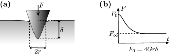
During indentation early stages (t 1 ms), the water in the agarose gel does not have time to flow away and the gel behaves as an incompressible elastic solid. The instantaneous force correlates with the shear modulus of the gel johnson_1985 as
| (2) |
where corresponds to the indenter tip position with respect to the gel surface and is the radius of the immersed indenter volume, as shown in figure 6 (a). After this time, the solvent can flow away and the agarose gel starts to relax, the force reaches a threshold value , and the gel behaves as a compressible elastic solid. The qualitative force behaviour is plotted in figure 6 (b).
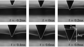
In our experiment, the needle solid injector can be considered as a dynamic micro-indentation measuring instrument with a conical indenter. The solid needle travels rapidly and does not allow the relaxation of the gel, and as consequence, the measured force is the instantaneous force in relation to the needle displacement. The micro-indentation measurement will be valid before the rupture of the surface agarose gel occurs, typically before a millisecond. Furthermore, the tip of the solid needle has a right circular conical geometry, as shown in figure 7, with height and base radius mm and mm, respectively. The needle tip position , and the gel surface deformation are obtained image sequences of the experiment.
The gel deformation during indentation process is plotted in figure 8 (a), where the zero position is defined in the initial agarose gel surface plane, i.e. the surface before injection. We observe three stages in the surface deformation: capillarity, indentation and injection. For a time ms, when the needle is approaching, the first contact is with a water film in the surface of the gel, formed due to the environmental humidity and evaporation. At the contact point, a liquid bridge wetting the needle is created due to the capillary action, and the visualized deformation is negative . The liquid bridge formation occurs too quickly to be captured in greater detail by our high-speed camera, however this phenomenon has been reported to play an important role in, for example, nano- and micro-indentation and AFM microscopy CHEN2008 ; Men2009 .
After that, when and ms, the needle pushes the agarose gel down and the dynamic micro-indentation process starts. Finally, the force applied by the needle against the agarose is high enough to induce gel rupture, and the ink delivery, effectively starting the injection process.
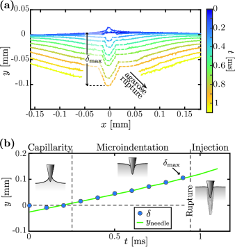
The maximum deformation caused by the needle tip displacement is plotted in figure 8 (b), blue dots. The expected needle position without the agarose gel is taken from the calibration process described in section II.1, green line. As we expected, and are in perfect agreement, which means the force exerted by the agarose gel is negligible compared to that exerted by the injector, meaning that the needle displacement is not affected by the gel.
In the micro-indentation stage, the maximum deformation measured is mm which corresponds to the applied force mN. We compare this force with as, , where mm. We can calculate the shear modulus of the skin surrogate, which represents the hardness, rigidity or stiffness of the material, obtaining . This value matches the shear modulus range, [30-3000] kPa, reported in the literature for the agarose concentrations used Normand ; NAYAR .
III.2 Stationary injection
Stationary injections were performed to understand the delivery process without the influence of specific factors, such as the needle injection angle, and translational speed with respect to the skin surrogate. The injection process in the case of a new needle holder loaded with PMU-black ink, is shown in figure 9 (a). We observed that it takes over 50 injections for the ink adhered to the needle surface to slide down, and initiate the delivery into the agarose; this instant is considered . After that, another 50 injections are needed to make a spot-width equivalent to the needle diameter mm. Finally, around 100 injections later, the injection width reaches a threshold value of mm. This plot shows that a unique injection is not enough to deliver a dose equivalent to the needle volume. Figure 9 (b) shows a high-resolution image sequence of the agarose gel after four injections without ink. The deformation of the agarose gel surface after only four injections is clearly visible. Also the gel is internally damaged, and a longitudinal hole of a diameter mm remains after one injection. After the second injection, a darker region inside the hole was observed, corresponding to a small water drop that came out of the agarose gel.
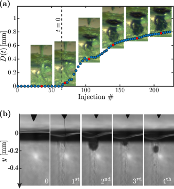
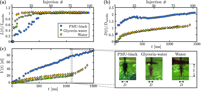
The injection process, from t=0, is compared for three of the inks: PMU-black ink, glycerin-water mixture and water. We calculate the ratio between the injection depth and the immersed needle length and between the injection width and the immersed needle diameter , as shown in figure 10 (a) and (b). The total needle length is around 2 mm, but the total immersed needle into the agarose can vary in dependence of the initial distance between the needle tip and the agarose surface, mainly due to the agarose surface unevenness. We observe that increases slower proportionally to the ink viscosity, but after injections they all reach a threshold value .
In the case of , the spreading behaviour is the opposite, for the PMU ink the change from zero to one is almost instantaneous and continues to increase up to in around 100 injections. For the aqueous solutions, saturates very quickly to 1, and the water and glycerin-water curves are almost indistinguishable (yellow diamonds and green squares in figure 10 (b)).
Assuming a circular conical injection shape, we estimate the injected volume as
| (3) |
and plotted in figure 10 (c). The image insets show the delivered volume at the same time ms or the same injection number . The plot shows that for the PMU ink increases at least twice faster than for the aqueous solutions, reaching volumes of nl and nl respectively, as expected from the and plots.
The large differences in behaviour are highly correlated with the differences in viscosity. For the solid needle used, with diameter mm and an injection frequency and amplitude Hz, mm, the shear rate of the ink film wetting the needle is
| (4) |
This means that the viscosities between the aqueous and the PMU inks are two order of magnitude different, from 1 mPas to 300 mPas. The PMU ink has a high adherence to the needle, making necessary to clean the needle in between experiments to prevent agglomeration. Moreover, the images show that the residual –not injected– ink accumulates in the surface, making the solid needle injection method highly inefficient for low viscous inks. Furthermore, there is remarkable difference of the liquid adhesion onto the needle when the viscosity increases from mPas to mPas. The images in figure 10 (c) show this difference, where the amount of ink remaining in the agarose surface is considerably higher for pure water than glycerin-water mixture.
III.3 Moving injection
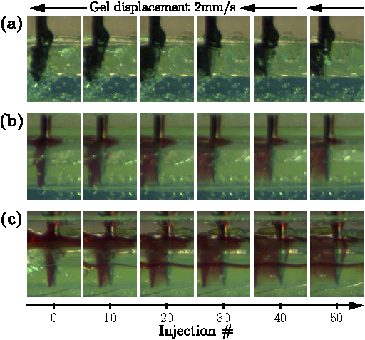
A qualitative characterisation of conventional tattoo injection processes is performed by moving the translation stage at 2 mm/s orthogonal to the hand-piece. A total number of 50 injections, corresponding to ms, are studied. Figure 11 shows a characteristic image sequence of the injection processes with different inks: (a) PMU-black ink, (b) glycerin-water mixture and (c) water. We observe that PMU ink has a much smaller spreading into the agarose gel, which we attribute to the several ingredients providing cohesion not present in aqueous solutions, i.e. glycerin-water mixture and water. In the case of the inks the surrogate saturation is faster and the ink oozes out on top of the agarose surface. This behaviour is expected because the agarose gel is mainly composed of water, therefore a maximum spreading is expected for the aqueous inks. Additionally, a residual volume of PMU ink remains adhered to the needle during the whole injection process. Pigment particles are the main responsible of the higher viscosity and density of PMU inks, giving such higher adhesion to the needle, and also limit the spreading into the agarose. In practice, the tailored composition and resulting properties of PMU ink, facilitate the drying process, and the needle needs to be cleaned constantly to prevent agglomeration as described in section II.3.
Images of the injected skin surrogate were taken immediately after the moving injection experiment. The agarose gel was cleaned before the imaging with a professional cleansing tonic (LaBina Aloe Vera tonic, PERMANENT-Line), in order to observe the post-injection result at the front and bottom, as shown in figure 12 for (a) PMU-red ink, (b) PMU-black ink, (c) glycerin-water mixture and (d) water. For the PMU inks, a well formed path line is visible in the front an bottom views. For the glycerin-dyed water solutions, the needle path is no longer visible due to its fast diffusion. However, we observed that the glycerin-water mixture presents less spread than pure water (see figure 11), in agreement with our observations described in section III.2. The bottom view shows that this spread distributes asymmetrically around the needle, rather the liquid spreads depending on the micro-characteristics of the agarose gel, i.e. its porosity and inhomogeneities.
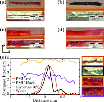
Those observations are quantified in figure 12 (e), the intensity of the injection path observed in the mirrow was calculated and averaged in the direction. A zoom-in of the mirrows for each ink is presented on the right. Two well defined peaks for the PMU inks are observed in the plot. The PMU-red peak is wider than the PMU-black, because the red ink is one order of magnitude more viscous, hence, the ink attaches better to the needle. The aqueous inks are completely spread in the agarose, showing an homogeneous average intensity. However, the glycerin-water mixture has a higher intensity, indicating that more ink has been delivered into the agarose.
IV Needle-free micro-jet injection method
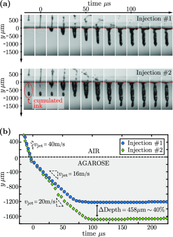
The needle-free micro-jet injector exhibited different penetration characteristics from what we observed with the solid needle injector. The needle-free injector creates liquid micro-jets with a tip diameter m and a total ejected volume of ca. 50 nl, with a 100% of the liquid delivered into the agarose for jet speeds larger than m/s, which indicates no splash-back of liquid due to the sufficient kinetic energy of the jets.
Figure 13 (a) shows image sequences of two successive needle-free injections of water jets entering the agarose at the same point. The penetration depths versus time for both injections are plotted in figure 13 (b). Both micro-jet speeds were 40 m/s before impacting the agarose. In the first injection, the jet speed drops to 16 m/s, which means a decrease of 85% in the micro-jet kinetic energy and is capable to penetrate 1 mm into the agarose. After the first jet opens a hole into the skin surrogate, each subsequent jet follows a micrometric longitudinal orifice into the gel. Therefore, the speed of the second micro-jet drops less than the previous one, up to 20 m/s, with its kinetic energy decreasing 75% and allowing a penetration into the agarose 40% deeper.
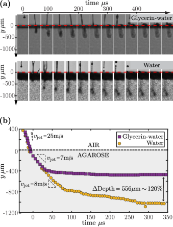
Experiments with glycerin-water mixture were performed in order to compare the injection process with the solid needle injection method. The shear rate experienced by the liquid jets is at least two order of magnitude higher than the shear rates provided by the solid needle injector. An image sequence of a single injection with micro-jet speed m/s, s, for pure water and glycerin-water mixture is shown in figure 14 (a). The differences observed in the agarose color and texture is an optical effect due to small illumination differences. It can be observed that, despite having the same initial jet velocities, water jets penetrate deeper than glycerin jets. The corresponding complete penetration events are plotted in figure 14 (b).
We observed that inertial effects are more relevant in the early stages of jetting and penetration, while viscous dissipation gains prominence towards the end-point injection. The penetration speed of both jets right after entering the agarose drops to a comparable speed, 8 m/s and 7 m/s respectively. Afterwards, during jet deceleration, water jets penetrate much deeper than glycerin-water jets (120% increase) due to the differences in the liquid viscosities of 25% ( mPas and mPas). Though not visible in these figures, water jets spread (laterally) faster into the agarose gel, while the spread area of glycerin jets remains almost the same after each injection.
| #1 injection | End point | ||||||||||
| Method | Ink | [kPa] | [J] | [nl] | [mm] | [mm] | [mm] | [mm] | |||
| Solid needle | PMU-black | 2400 | 13 | 0.042 | 4.2 | 424 | 0.047 | 0.129 | 0.005 | 0.8 | |
| Glycerin-water | 0.033 | 3.3 | 338 | 0.154 | 0.021 | 0.004 | 0.4 | ||||
| Water | 0.027 | 2.7 | 283 | 0.197 | 0.019 | 0.004 | 0.4 | ||||
| Needle-free micro-jet | Glycerin-water | 3.2 | 1.73 | 2.85 | 5.7 | 8.9 | 0.450 | 0.192 | 88.1 | - | - |
| Water | 4.32 | 16.16 | 3.2 | 20.2 | 1.2 | 0.205 | =1.65 | 0.205 | |||
In contrast with the solid needle injector, no evident damage was observed on the agarose surface after multiple injections recorded with an image resolution of 150 pixels per millimeter. Moreover, the agarose shows a capacity of self-recovery as the path created by the micro-jet closes, and encapsulates the injected ink, see figure 13 (a) first image, second injection.
V Comparison of injection methods
The fact that no solid object is needed to rupture the surrogate with the needle-free micro-jet injector is a clear advantage in practical terms. To make a fair comparison, the agarose gel surface rupture and damage, the spreading of the ink, among other observations are detailed in this section. The values calculated for all inks and both injection methods are presented in table 1, using the results in figure 10, for the solid needle, and figure 13 and 14, for the needle-free micro-jet.
The electric energy supplied to the injectors is calculated as . The solid needle injector input power is W, and the time of a single injection is s, with a consumed energy mJ. The needle-free micro-jet injector input power corresponds to the laser power W, and the corresponding time needed for the liquid to cavitate ms, corresponding to mJ. The kinetic energy transferred from the liquid to the skin is calculated as , where the speed for the solid needle is and for the jet is . Therefore, the injection efficiency in terms of energy per injection is calculated as . We have calculated that the needle-free micro-jet injector has a three orders of magnitude higher than the solid injector.
The liquid volume deposited by the solid needle injector in each injection was estimated as the thickness of the liquid film around the needle tip:
| (5) |
where is the liquid viscosity, the liquid density, the flow velocity and the gravitational acceleration. This equation assumes that the flow velocity corresponds to the needle velocity, and that the surface tension role is negligible LANDAU1988 ; RIO2017 . The constant is taken as 0.8, which is a standard value for most Newtonian fluids. The ink volume around the needle is estimated as the volume of a hollow cylinder with inner radius as the needle radius and outer radius .
The injection efficiency in terms of volume injected per injection event, we calculate it as the ratio between the deposited (solid needle) or ejected (needle-free micro-jet injector) volume , and the volume remaining inside the agarose gel. For the former case, this is defined as the moment in which of solid needle retracts, and the latter is after the hole in the agarose closes. This efficiency is represented as . For the solid needle, the efficiency increases with each new injection because of the remaining ink from prior injections. There is, however, excess of liquid on the top of the agarose gel that does not penetrate at all, and contributes of the well known ink loss of 50% in tattooing and permanent make up procedures (personal communication with several tattoing and PMU companies). The is much higher for the needle-free micro-jet injector than the solid needle: five orders of magnitude.
In order to quantify the skin rupture and penetration characteristics, we compare the local stress induced by the solid needle and the jet impact, with a material-dependent critical local stress as proposed before schramm2002transdermal . We define a new quantity, the penetration strength , as the ratio between the injection pressure and the skin surrogate shear modulus kPa calculated in section III.1. In the case of the solid needle, the injection pressure was calculated as the ration between the rupture force and the needle cross sectional area:
| (6) |
where mm is the radius of the inmersed needle volume at the moment of the maximum deformation of the skin surrogate, as explained in section III.1. The pressure exerted by the jet onto the skin is , where is the density of the liquid, and the jet speed schramm2002transdermal .
The penetration depth and diameter in the latest stages or end-point of injection –after 50 injections for the solid needle, and after two injections for the needle-free injectors– show two interesting results. First, that with only two jets is possible to reach the same depth as with solid needles. Second, that the injection resolution in spreading value (), which corresponds to the practical level of detail in tattooing, is half for the jet injections. The current experimental setup for jet injections did not allow us to have the same reproducibility of conditions to reach larger number of injections. Contrary to the solid needle injections, each new jet carries a slightly higher velocity because of the reduction in liquid inside the microfluidic chamber. In future studies we will attempt to design a microfluidic device that ensures all jets in a sequence are ejected with the same velocity and total volume delivered.
VI Conclusions
We consider that this study will advance the knowledge of injection processes into soft substrates based on solid needles and needle-free micro-jet injectors. Our novel needle-free micro-jet injector employing thermocavitation is still in early development phases, however, the results indicate that the injection outcomes are superior to solid needle injectors in several aspects. Further work is required, particularly aimed at increasing the repeatability, frequency of injections, and overcoming challenges related to the use of commercial inks with unknown ingredients. Our results indicate that:
-
•
The power consumption of needle-free jet injections, 0.5 W, is an order of magnitude lower than the solid injector (7 W). This has practical relevance in future scenarios, where portability of injector devices is limited by the need of incorporating heavy batteries.
-
•
The calculated penetration strength S, reflects the proportional final damaged state of the skin surrogate. Values of S slightly above unity (jet injections) seem to correspond to an effective penetration with minimal damage, in contrast with irreversible skin surrogate deformations when S10 (solid needle).
-
•
The damage to the gel during the moving injections indicate that needle-free micro-jet injectors could have less negative effect than solid needles when injecting into skin. In real-life conditions, the displacement velocity and pressure applied with a hand-piece can fluctuate, damaging the skin because of the hardness needles.
-
•
The injection spreading increase with decreasing ink viscosity. However, the volume and energy efficiencies seem to increase proportionally to the viscosity of inks.
-
•
The injection efficiencies, and , are higher for the needle-free micro-jet injector, with comparable end-point injections. The needle-free micro-jet injector in a single injection reaches penetration depths and widths comparable to 50 injections with a solid needle. Even though multiple injections were not possible with the current needle-free micro-jet injector, the higher efficiency values demonstrate the superiority over the older solid needle method. For needle-free micro-jet injectors to compete with established injection methods in real-life scenarios, however, future designs should give multiple and reproducible injections, e.g. with multiple nozzles or microfluidic geometries ensuring self-refill of ink after each jet.
We conclude that needle-free micro-jet injections hold potential to mitigate health problems associated to needle-based injections, and avoid technical limitations of solid needle injections in medical treatments, e.g. vaccines, scar camouflaging, alopecia, etc. The reduction of environmental contamination with needle-free injections could be huge, while benefiting millions of people using needles on a daily basis for medical and cosmetic uses. With a long list of challenges ahead, we believe there will be a time, not far from now, when needle-free micro-jet injectors will be reliable, safer, and efficient liquid delivery platforms, and where needles will not be that much needed.
Acknowledgements
We would like to thank Stefan Schlautmann and Frans Segerink for their technical support during fabrication and optical setup construction. To Edgerton’s centre for the use of the Phantom high-speed camera and illumination. The material support of PERMANENT-Line GmbH & Co. KG. and MT-Derm is kindly acknowledged, as well as the practical and theoretical training offered by PERMANENT-Line GmbH & Co. KG. DFR acknowledges the recognition from the Royal Dutch Society of Sciences (KHMW) that granted the Pieter Langerhuizen Lambertuszoon Fonds, 2016.
References
References
- (1) K. Sperry, “Tattoos and tattooing. part i: History and methodology.,” The American journal of forensic medicine and pathology, vol. 12, no. 4, pp. 313–319, 1991.
- (2) N. Kluger and V. Koljonen, “Tattoos, inks, and cancer,” The lancet oncology, vol. 13, no. 4, pp. e161–e168, 2012.
- (3) P. S. Islam, C. Chang, C. Selmi, E. Generali, A. Huntley, S. S. Teuber, and M. E. Gershwin, “Medical complications of tattoos: a comprehensive review,” Clinical reviews in allergy & immunology, vol. 50, no. 2, pp. 273–286, 2016.
- (4) R. Friedman, D. Antoine, S. Talamo, P. J. Reimer, J. H. Taylor, B. Wills, and M. A. Mannino, “Natural mummies from predynastic egypt reveal the world’s earliest figural tattoos,” Journal of Archaeological Science, vol. 92, pp. 116–125, 2018.
- (5) J. Serup, N. Kluger, and W. Bäumler, Tattooed skin and health. Curr. Probl. Dermatol. Karger Medical and Scientific Publishers, 2015.
- (6) P. Piccinini, S. Pakalin, L. Contor, I. Bianchi, and C. Senaldi, “Safety of tattoos and permanent make-up. final report,” JRC Science for policy report EUR, vol. 27947, 2016.
- (7) H. Petersen and K. Roth, “To tattoo or not to tattoo,” Chemie in unserer Zeit, vol. 50, no. 1, pp. 44–66.
- (8) D. Jang, D. Kim, and J. Moon, “Influence of fluid physical properties on ink-jet printability,” Langmuir, vol. 25, no. 5, pp. 2629–2635, 2009.
- (9) C. A. Grant, P. C. Twigg, R. Baker, and D. J. Tobin, “Tattoo ink nanoparticles in skin tissue and fibroblasts,” Beilstein journal of nanotechnology, vol. 6, p. 1183, 2015.
- (10) Y.-C. Kim, Skin Vaccination Methods: Gene Gun, Jet Injector, Tattoo Vaccine, and Microneedle, pp. 485–499. Berlin, Heidelberg: Springer Berlin Heidelberg, 2017.
- (11) A. Taberner, N. C. Hogan, and I. W. Hunter, “Needle-free jet injection using real-time controlled linear lorentz-force actuators,” Medical engineering & physics, vol. 34, no. 9, pp. 1228–1235, 2012.
- (12) X. Li, B. Ruddy, and A. Taberner, “Characterization of needle-assisted jet injections,” Journal of Controlled Release, vol. 243, pp. 195–203, 2016.
- (13) S. Mitragotri, “Current status and future prospects of needle-free liquid jet injectors,” Nat. Rev. Drug Discov., vol. 68, p. 341, 2006.
- (14) A. Arora, Liquid and Powder Jet Injectors in Drug Delivery: Mechanisms, Designs, and Applications, pp. 221–230. Berlin, Heidelberg: Springer Berlin Heidelberg, 2017.
- (15) S. Münch, J. Wohlrab, and R. Neubert, “Dermal and transdermal delivery of pharmaceutically relevant macromolecules,” Eur. J. Pharm. Biopharm., vol. 119, pp. 235–242, 2017.
- (16) J. Baxter and S. Mitragotri, “Jet-induced skin puncture and its impact on needle-free jet injections: Experimental studies and a predictive model,” J. Controlled Release, vol. 106, no. 3, pp. 361 – 373, 2005.
- (17) J. Schramm and S. Mitragotri, “Transdermal drug delivery by jet injectors: energetics of jet formation and penetration,” Pharm. Res., vol. 19, no. 11, pp. 1673–1679, 2002.
- (18) G. Nelmes, “The peace gun and the eradication of smallpox,” Military Medicine, vol. 182, no. 3-4, pp. 1512–1513, 2017.
- (19) N. C. Hogan, A. J. Taberner, L. A. Jones, and I. W. Hunter, “Needle-free delivery of macromolecules through the skin using controllable jet injectors,” Expert Opin. Drug Deliv., vol. 12, no. 10, pp. 1637–1648, 2015.
- (20) C. B. Rodríguez, C. W. Visser, S. Schlautmann, D. F. Rivas, and R. Ramos-Garcia, “Toward jet injection by continuous-wave laser cavitation,” Journal of biomedical optics, vol. 22, no. 10, p. 105003, 2017.
- (21) J. Serup, N. Kluger, and W. Bäumler, Tattooed skin and health. Tattoo Machines, Needles and Utilities. Karger Medical and Scientific Publishers, 2015.
- (22) S. F. Rastopov and A. T. Sukhodolsky, “Sound generation by thermocavitation-induced cw laser in solutions,” in Optical Radiation Interaction with Matter, vol. 1440, pp. 127–135, International Society for Optics and Photonics, 1991.
- (23) J. P. Padilla-Martinez, C. Berrospe-Rodriguez, G. Aguilar, J. C. Ramirez-San-Juan, and R. Ramos-Garcia, “Optic cavitation with CW lasers: A review,” Phys. Fluids, vol. 26, p. 122007, Dec. 2014.
- (24) C. Berrospe-Rodriguez, C. W. Visser, S. Schlautmann, R. Ramos-Garcia, and D. Fernandez Rivas, “Continuous-wave laser generated jets for needle free applications,” Biomicrofluidics, vol. 10, no. 1, p. 014104, 2016.
- (25) H. Wijshoff, “The dynamics of the piezo inkjet printhead operation,” Phys. Rep., vol. 491, no. 4, pp. 77–177, 2010.
- (26) W. J. Grande, “Direct capillary printing in medical device manufacture,” Medical Coatings and Deposition Technologies, pp. 309–372, 2016.
- (27) M. A. Kendall, “The delivery of particulate vaccines and drugs to human skin with a practical, hand-held shock tube-based system,” Shock Waves, vol. 12, no. 1, pp. 23–30, 2002.
- (28) Y. Deng, G. Winter, and J. Myschik, “Preparation and validation of a skin model for the evaluation of intradermal powder injection devices,” Eur. J. Pharm. Biopharm., vol. 81, no. 2, pp. 360–368, 2012.
- (29) J. Schramm-Baxter, J. Katrencik, and S. Mitragotri, “Jet injection into polyacrylamide gels: investigation of jet injection mechanics,” J. Biomech., vol. 37, no. 8, pp. 1181–1188, 2004.
- (30) R. Williams, Jet Injection of Viscous Fluids. PhD thesis, ResearchSpace@ Auckland, 2016.
- (31) Y. Tagawa, A. E. Oudalov, N.and Ghalbzouri, C. Sun, and D. Lohse, “Needle-free injection into skin and soft matter with highly focused microjets,” Lab Chip, vol. 13, pp. 1357–1363, 2013.
- (32) M. Ahearne, Y. Yang, A. J. El Haj, K. Y. Then, and K.-K. Liu, “Characterizing the viscoelastic properties of thin hydrogel-based constructs for tissue engineering applications,” Journal of The Royal Society Interface, vol. 2, no. 5, pp. 455–463, 2005.
- (33) Y. Hu, X. Zhao, J. J. Vlassak, and Z. Suo, “Using indentation to characterize the poroelasticity of gels,” Applied Physics Letters, vol. 96, no. 12, p. 121904, 2010.
- (34) D. M. Ebenstein and L. A. Pruitt, “Nanoindentation of soft hydrated materials for application to vascular tissues,” Journal of Biomedical Materials Research Part A, vol. 69A, no. 2, pp. 222–232.
- (35) G. Constantinides, Z. I. Kalcioglu, M. McFarland, J. F. Smith, and K. J. V. Vliet, “Probing mechanical properties of fully hydrated gels and biological tissues,” Journal of Biomechanics, vol. 41, no. 15, pp. 3285 – 3289, 2008.
- (36) C.-Y. Hui, Y. Y. Lin, F.-C. Chuang, K. R. Shull, and W.-C. Lin, “A contact mechanics method for characterizing the elastic properties and permeability of gels,” Journal of Polymer Science Part B: Polymer Physics, vol. 44, no. 2, pp. 359–370.
- (37) M. Galli, K. S. Comley, T. A. Shean, and M. L. Oyen, “Viscoelastic and poroelastic mechanical characterization of hydrated gels,” Journal of Materials Research, vol. 24, no. 3, p. 973 979, 2009.
- (38) K. L. Johnson, Contact Mechanics. Cambridge University Press, 1985.
- (39) S. Chen and A. Soh, “The capillary force in micro- and nano-indentation with different indenter shapes,” International Journal of Solids and Structures, vol. 45, no. 10, pp. 3122 – 3137, 2008.
- (40) Y. Men, X. Zhang, and W. Wang, “Capillary liquid bridges in atomic force microscopy: Formation, rupture, and hysteresis,” The Journal of Chemical Physics, vol. 131, no. 18, p. 184702, 2009.
- (41) V. Normand, D. L. Lootens, E. Amici, K. P. Plucknett, and P. Aymard, “New insight into agarose gel mechanical properties,” Biomacromolecules, vol. 1, no. 4, pp. 730–738, 2000.
- (42) V. Nayar, J. Weiland, C. Nelson, and A. Hodge, “Elastic and viscoelastic characterization of agar,” Journal of the Mechanical Behavior of Biomedical Materials, vol. 7, pp. 60 – 68, 2012. 7th TMS Symposium on Biological Materials Science.
- (43) L. Landau and B. Levich, “Dragging of a liquid by a moving plate,” in Dynamics of Curved Fronts, pp. 141 – 153, San Diego: Academic Press, 1988.
- (44) E. Rio and F. Boulogne, “Withdrawing a solid from a bath: How much liquid is coated?,” Advances in Colloid and Interface Science, vol. 247, pp. 100 – 114, 2017.