CRITICAL FIELDS OF Nb3Sn PREPARED FOR SUPERCONDUCTING CAVITIES
Abstract
Nb3Sn is currently the most promising material other than niobium for future superconducting radiofrequency cavities. Critical fields above 120 mT in pulsed operation and about 80 mT in CW have been achieved in cavity tests. This is large compared to the lower critical field as derived from the London penetration depth, extracted from low field surface impedance measurements. In this paper direct measurements of the London penetration depth from which the lower critical field and the superheating field are derived are presented. The field of first vortex penetration is measured under DC and RF fields. The combined results confirm that Nb3Sn cavities are indeed operated in a metastable state above the lower critical field but are currently limited to a critical field well below the superheating field.
I Introduction
The performance of Nb as a material for superconducting radiofrequency (SRF) cavities is reaching fundamental limits in terms of surface resistance and peak surface magnetic field. Other superconductors are being developed to offer a way to push performance beyond Nb technology. One potential alternative material is Nb3Sn, a Type-II superconductor with a relatively high Ginzburg Landau parameter ( close to stoichiometry Godeke2006 ) as opposed to about 1.4 for high purity Nb. Nb3Sn has a relatively high critical temperature of about 18 K, twice that of Nb which allows, for example, to operate RF cavities at 4.2 K with the same losses as for Nb at 2 K, if dominated by intrinsic losses from thermally activated quasiparticles, so called BCS losses. This is of high relevance, since cavities can be operated with liquid helium at atmospheric pressure which considerably simplifies the required cryo plant and reduces its operating and investment costs significantly. The lower critical field for Nb3Sn is about 38 mT close to stoichiometry, as opposed to 170 mT for clean Nb. To obtain accelerating gradients above 10 MV/m for = elliptical cavities Nb3Sn has therefore either to be operated in the mixed phase, with the penetrated vortices being pinned to avoid strong dissipation, or in a metastable vortex free state. This state can potentially be sustained up to the superheating field which is about 440 mT for Nb3Sn, compared to about 240 mT for Nb. Superconducting material parameters at T=0 K relevant to this work of Nb and Nb3Sn are presented in Tab. 1. The values of and are for clean Nb and Nb3Sn close to stoichiometry, while is computed from PhysRevB.83.094505
| (1) |
| Property | Nb | Nb3Sn |
|---|---|---|
| [K] | 9.25 finnemore1966superconducting | 18 Godeke2006 |
| (0K) | 1.4 finnemore1966superconducting | 34 Godeke2006 |
| [nm] | 39 MattisBardeenTheory | 5.7(0.6) orlando1979critical |
| [nm] | 27(3) Suter2005 | 65Poole -89Hein1999 |
| (0K) [mT] | 174 finnemore1966superconducting | 38 Godeke2006 |
| (0K) [mT] | 199 finnemore1966superconducting | 520 Godeke2006 |
| (0K) [mT] | 240 PhysRevB.83.094505 | 440 PhysRevB.83.094505 |
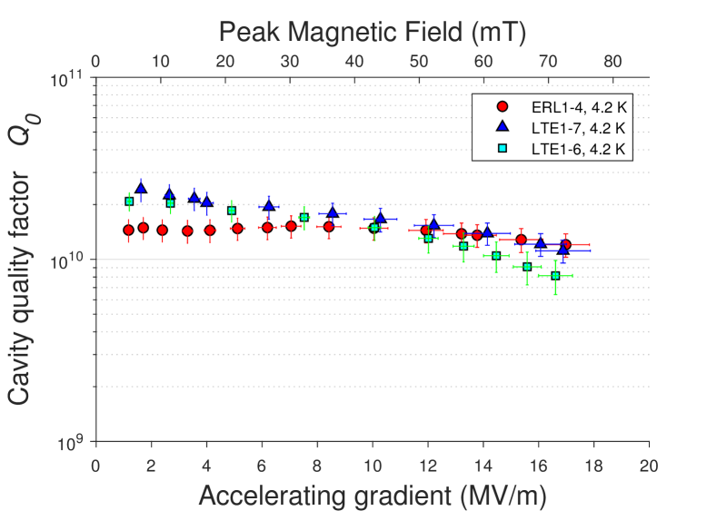
A Nb3Sn SRF program began at Cornell University in 2009 posen2014prstab ; posen2015apl . The program focused on coating fine grain bulk niobium cavities with a layer of of Nb3Sn via the deposition of tin vapor in a vacuum furnace. Cold tests of the cavities revealed (see Fig. 1): (1) reproducible high values on the order of at 4.2 K, (2) reproducible sustaining of this high to useful accelerating gradients above 16 MV/m corresponding to peak magnetic values in excess of 70 mT. The attained values are significantly higher than as derived from the electron mean free path extracted from low field surface impedance measurements, suggesting that vortex penetration at is not a limitation posen2015prl . The scope of this paper is to test by direct measurements whether this conclusion is indeed substantiated.
Using the low energy muon spin rotation (LE-SR) technique from PSI the penetration depth is measured directly. This allows to calculate . So called surface muons111These muons are called surface muons because they are produced from pions which stop and decay close to the surface of the production target. available at TRIUMF are used to derive the DC field of first flux entry. The measured values are compared to the calculated . Finally, the critical RF field is tested using a Quadrupole Resonator (QPR) at HZB. Samples of specific shape adapted to the experiments have been produced using the same vapor diffusion technique as for the SRF cavities at Cornell.
II Sample preparation
All samples are made from fine grain niobium of high residual resistivity ratio (RRR>300) and were coated with a thick layer of Nb3Sn at Cornell. The coating procedure for the used samples is the same as successfully used on the RF cavities posen2017nb3sn . Coating lasts 3 hours, with the cavity at 1100 C and the tin source at 1200 C.
II.1 SR samples
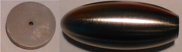
For the LE-SR experiments a coin-shaped sample was cut from a Nb sheet, while for the surface SR measurements an ellipsoid sample is used which has been machined from bulk Nb. The coin is 3 mm thick and 20 mm in diameter. A hole is drilled through the center of the sample for mounting the sample during coating. The prolate ellipsoid is 9 mm in radius on the minor axis with a 22.9 mm semi-major axis. A threaded hole is drilled in one end for mounting the sample during coating and test. The muons are implanted at the opposite pole.
In the solid ellipsoid the Meissner state is supported by screening currents that augment the field at the equator and reduce the field at the poles. When the flux at the equator reaches the field of first vortex penetration , which can be or in case of a surface barrier up to , fluxoids will nucleate at the equator and redistribute uniformly inside the superconductor due to vortex repulsion. Pin-free ellipsoidal bulk samples produce a uniform vortex flux density in the mixed state since the inward directed driving force on the vortex by the surface screening currents is compensated by the vortex line length that increases for fluxoids closer to the ellipsoid axis. The magnetic field at the equator will be enhanced to where is the applied field and the demagnetizing factor. In our geometry the ellipsoid demagnetizing factor is , therefore the measured field of first penetration . If the temperature is above 9.25 K, the critical temperature of niobium, the geometry is a superconducting Nb3Sn shell. The field will still break in at but the vortex lines will directly snap to the center since the flux line length in the superconducting shell is actually less near the ellipsoid axis. The coin sample is tested in the Meissner state using the LE-SR technique. Due to its geometry the field is enhanced by 15 % at the edge and 9 % in the midplane. For details refer to Junginger_muSR_Overview . The samples used for SR are shown in Fig. 2.
II.2 QPR sample
The QPR sample chamber has a “top hat”-like shape with its upper outside being exposed to the RF field inside the resonator, see Fig. 3. The actual sample is a disk of 75 mm diameter and 10 mm in height. It is electron-beam welded to a tube of 2 mm wall thickness which in turn is welded to the “brim”. The bulk material of all parts is fine grain niobium with the Nb3Sn coating covering all outer (and inner) surfaces. For mounting into the QPR the superconducting part of the sample chamber has to be connected to a double-sided CF100 flange. Commonly, QPR samples are brazed to this stainless steel flange. The process of coating with Nb3Sn requires a substrate of high purity niobium, furthermore, heat related changes to the sample due to brazing or welding after coating have to be prevented. In order to enable coating with Nb3Sn according to the process used for SRF cavities, a detachable connection of superconducting sample chamber and stainless steel bottom flange was implemented. An indium wire gasket of 1 mm diameter was used providing both thermal link to the liquid helium bath and UHV compatible sealing of the cavity vacuum. Prior to coating with Nb3Sn the niobium substrate was characterized at HZB showing low residual rf surface resistance of about and high RF critical field phdkleindienst . For details on the QPR refer to qprhzb2015 ; phdkeckert .

III Methods
III.1 The SR technique
In a SR experiment, 100 % spin polarized muons are implanted one at a time into the sample, stop in interstitial sites and precess with characteristic Larmor frequencies determined by the local magnetic field . When the muon decays it emits a fast positron which has a propensity to emerge along the direction of the muon spin. Two positron detectors (symmetrical placed around the sample) detect the positron signal. The time evolution of the muon spin polarization gives information about the local field experienced by the muon. For a general introduction to SR refer to yaouanc2011muon ; Schenk . If the field has fully penetrated, or the measurement is performed in the London layer using the LE-SR technique, an oscillating depolarization will be observed
| (2) |
with
| (3) |
where 13.55 kHz/G is the gyromagnetic ratio of the muon and a phase which can depend on the external field. The leading term of Eq. 2 describes the damping of the oscillation assuming a Gaussian distribution of the local field around with a full width at half maximum .
If the sample is in the Meissner state and the muon is implanted in the bulk with the surface muon beam, the muon does not sense the external magnetic field. The local magnetic field sensed in this case is from the nuclear dipolar fields. In case of significant muon diffusion, which is the case for high RRR niobium Junginger_muSR_Overview , the polarization is described by the dynamic zero field Kubo-Tuyabe function Hayano . Therefore, in the field of first vortex penetration measurements will be sensed for low applied field. When the field has fully penetrated the sample Eq. 2 describes the depolarization. If the field penetrates gradually, which is the case if there is pinning, there can be coexisting field free and penetrated areas. In this case, the total polarization function is comprised of two terms as
The first term is due to the volume fraction being in the Meissner state and the second term describes the volume fraction containing magnetic field. These fractions are represented by the coefficients and , which can take values from 0 to 1. At zero magnetic field inside the sample equals 1 and equals 0. A significant decrease of from its low field value equal to 1 signifies vortex penetration. For details refer to Junginger_muSR_Overview .
Two different muon beams are used for these studies. At TRIUMF so called surface muons (kinetic energy 4.1 MeV) are used with an implantation depth of about 130 m deep in the bulk of a niobium sample. If measured above the critical temperature of niobium, the geometry of the samples can therefore be considered as a superconducting shell and the screening of the Nb3Sn coating alone can be determined. This allows to detect the transition from the Meissner to a vortex state. For details refer to Junginger_muSR_Overview .
At PSI, a low energy muon beam is available prokscha2008new ; morenzoni2000low . By varying its energy, it can be used as a probe for local magnetism at various depths between a few and up to about 300 nm depending on the material density. Applying a field below this allows to measure the local field as a function of depth. This experiment therefore allows for a direct measurement of the London penetration depth.
III.2 Quadrupole Resonator (QPR)
The QPR Mahner:611593 ; Junginger:Revscientinstr12 is a dedicated sample test cavity which can be used to measure the RF quench field as a function of temperature. It is operated in a bath cryostat filled with superfluid helium which is pressure stabilized providing stable RF conditions. Regarding the sample chamber, only the stainless steel flange at its bottom is in contact with liquid helium. The RF sample disk is cooled via heat conduction through the sidewalls of the sample chamber. The bottom side of the sample disk is equipped with a resistive DC heater in its center and a calibrated Cernox temperature sensor at the radial position of highest RF field. Using the heater, arbitrary sample temperatures between 1.8 and approx. can be achieved. The heater power is PID controlled, providing temperature stability better than at 18 K. Due to the weak thermal link to the liquid helium bath and the low thermal conductivity of the stainless steel flange, the maximum temperature difference along the RF surface is about 0.1 K at 18 K. Note that only the sample temperature is changed, whereas the helium bath temperature is kept at 1.8 K throughout the entire measurement.
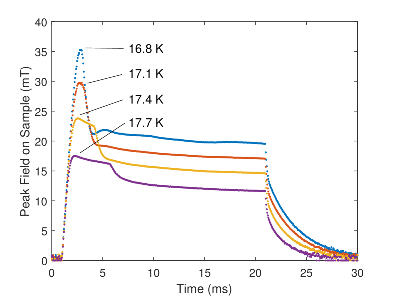
In order to probe the RF critical field of the sample, single rectangular RF pulses are used. A quench decreases the loaded quality factor of the resonator, leading to a drop of transmitted RF power. The transmitted power is recorded with a time resolution of , allowing for a precise determination of the peak RF field. Fig. 4 shows four examples of transmitted RF pulse traces, converted to peak RF field on the sample. The temperature measurement is not fast enough to capture the temporal evolution of the sample but it is used to differentiate between a quench occurring on the sample or somewhere else inside the resonator.
The field configuration inside the QPR provides an advantage over tests using elliptical cavities: In case of a 1.3 GHz TESLA-shaped single-cell cavity the ratio of peak magnetic field and square root of stored energy is given by . Hence, a stored energy of is required to achieve . For the QPR this is reduced significantly:
| (5) |
In order to suppress pre-quench heating the RF time constant has to be small, but reducing the loaded quality factor increases the required RF drive power. Assuming the cavity to be strongly overcoupled, the required forward power is given by . This yields for the case of equal rise time and magnetic field:
| (6) |
Clearly, nearly two orders of magnitude more RF power must be applied to the TESLA cavity to achieve the quench field. The maximum achievable field level inside the QPR is limited by the cavity quench field at about 120 mT. Hence, the critical field can only be measured at elevated temperatures with being dominated by BCS losses. Using yields for localized heating
| (7) |
For this reason, the requirement of equal rise time in QPR and cavity measurements can be relaxed which in turn reduces the necessary RF power. Furthermore, time-resolved numerical simulations of the QPR sample chamber show a significant impact of the sample thickness on the temperature dynamics phdkeckert . Due to the thermal diffusivity of niobium, the sample disk being 10 mm in thickness reduces the non-equilibrium temperature rise during the RF rise time compared to cavity-grade material of -3 mm thickness. Note that the scenario of a thin sample disk is approximately comparable to the situation of a single-cell cavity test at temperatures above 4.2 K with inefficient cooling by gaseous helium only. Hence, at HZB a solid-state amplifier with a few hundred watts is sufficient, while measurements with TESLA cavities had to be performed with MW-class klystrons phdkeckert ; hays1997 ; posen2015prl .
IV Results
IV.1 Low energy muon spin rotation
Muons have been implanted with energies between 3.3 and 17.3 keV corresponding to mean stopping depths between 15 and 55 nm, see Fig. 5. The applied field was =10 mT and the temperature 5 K. For each depth the local magnetic field sensed by the muons is derived from the time evolution of the muon spin polarization function P(t) using Eq. 2.

The data has been analyzed using the musrfit software Suter . The whole data was also collectively fitted to the one-dimensional London model using the BMW libraries for musrfit BMW_libs taking into account the stopping distribution of the muons in the material. For an isotropic local superconductor a solution of the form
| (8) |
is obtained, where is the distance from the surface. The fit parameters found are =11.4 mT and =160.5(3.9) nm. is expected to change according to
| (9) |
from which =160.0(3.9) nm can be derived being only 0.3 % shorter than . The lower critical field can be expressed as tinkham2004introduction
| (10) |
where is the magnetic flux quantum. To obtain the Ginzburg-Landau parameter from the measured value of , literature values of the London penetration depth and the BCS coherence length are required. A formula is derived using the fact that the BCS and the Ginzburg-Landau coherence length are both correlated to the magnetic flux quantum tinkham2004introduction
| (11) |
Note that and are both fundamental material properties defined for the clean stoichiometric material. The values taken from literature can be found in Tab. 1. From =160 nm, =60(15) and =28(2) mT are derived. The thermodynamic critical field can be calculated using tinkham2004introduction
| (12) |
The value of 600(100) mT is consistent with 520 mT reported in Godeke2006 , see Tab. 1. Finally, the superheating field is calculated using Eq. 1 to be 500(120) mT. On a side note the value of is 14 % larger than the applied field. This field enhancement is close to what is expected at the edge of this coin shaped sample (=0.15)222A more thorough analysis would have to take the complete magnetic field and muon stopping distributions into account..
IV.2 Surface muon spin rotation
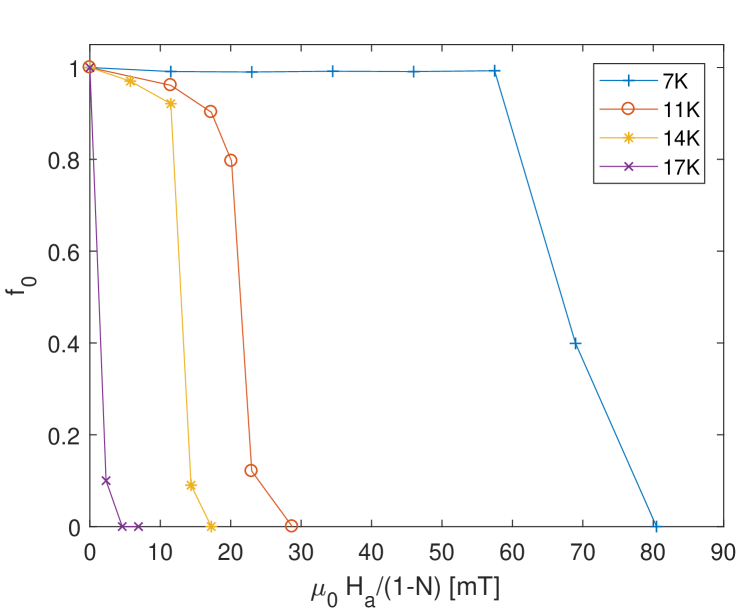
The muon polarization function was measured as a function of applied field at three temperatures above and one below using surface muons implanted 130 m in the bulk. Fig. 6 displays the fit parameter as derived from Eq. III.1 as a function of applied field divided by 1-, where is the demagnetization factor of the ellipsoid. From this plot the intrinsic DC field of first vortex penetration can be derived for each temperature as the field for which significantly deviates from 1. For temperatures above the geometry is a 2 m superconducting shell, while below both materials can potentially provide shielding and it is not possible to directly derive the field of first vortex penetration for the Nb3Sn layer alone. The field of first vortex penetration for the Nb3Sn shell at 0 K is derived by extrapolation taking only data above 9.25 K into account. A value of =28(12) mT is found, see discussion.
IV.3 Quadrupole Resonator
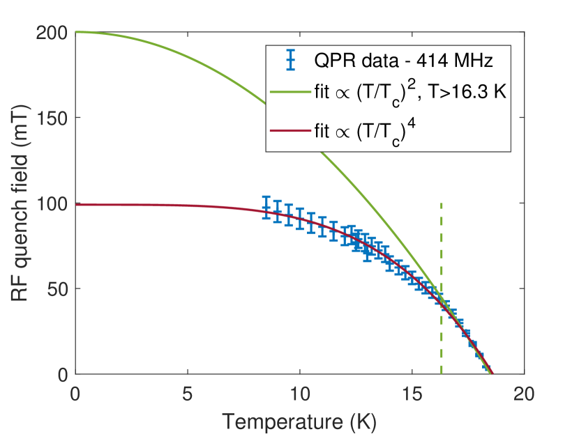
The RF quench field was measured at various temperatures , see Fig. 7. This temperature limitation was due to the fact that RF instabilities and the quenching resonator ruled out measurements for .

The measured data can be described by the empirical relation for the temperature dependence of the critical thermodynamic field
| (13) |
only in the temperature range . This choice is somewhat arbitrary, but expanding the fit data range to lower temperature reduces the fit quality significantly. Extrapolation to low temperature yields = and =. Note that the predicted temperature dependence for is almost identical to that of .
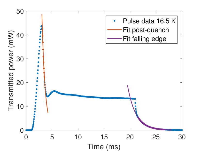
In order to estimate a possible impact of pre-quench RF heating, which would falsify the assumed sample temperature, the acquired pulse shapes are investigated. After a quench, the loaded quality factor of the QPR is dominated by the partially normal conducting sample. The corresponding decay time is determined by fitting the drop of transmitted power (see Fig. 8). After the RF drive power is switched off, the sample becomes superconducting within few and the following unperturbed decay time is again obtained from an exponential fit (see Fig. 8).
From and the electrical resistivity of Nb3Sn in the normal conducting state ( valente2016 ), the quenched sample area is estimated yielding . Note that for the increasing temperature dependent surface resistance of the sample begins to reduce the decay time of the superconducting state (see Fig. 9). For , the change of loaded quality factor decreases such, that no steep decrease of transmitted power is observed anymore and fits of are meaningless to deduce the quenched sample area. The increase observed for the 17 K point in Fig. 9 hence is considered to reflect this measurement difficulty. This is also visible in the pulse traces shown in Fig. 4.
However, the fact that for , and hence the quenched area, do not depend on temperature (see Fig. 9) is a strong indication of a localized quench spot without excessive pre-quench heating affecting the measurement accuracy. This is in agreement with a quench limitation set by vortex line nucleation (see the following discussion). In comparison, measurements of a bulk niobium sample with RF quench fields consistent with the global superheating limit showed a quench area of about phdkeckert .
V Discussion
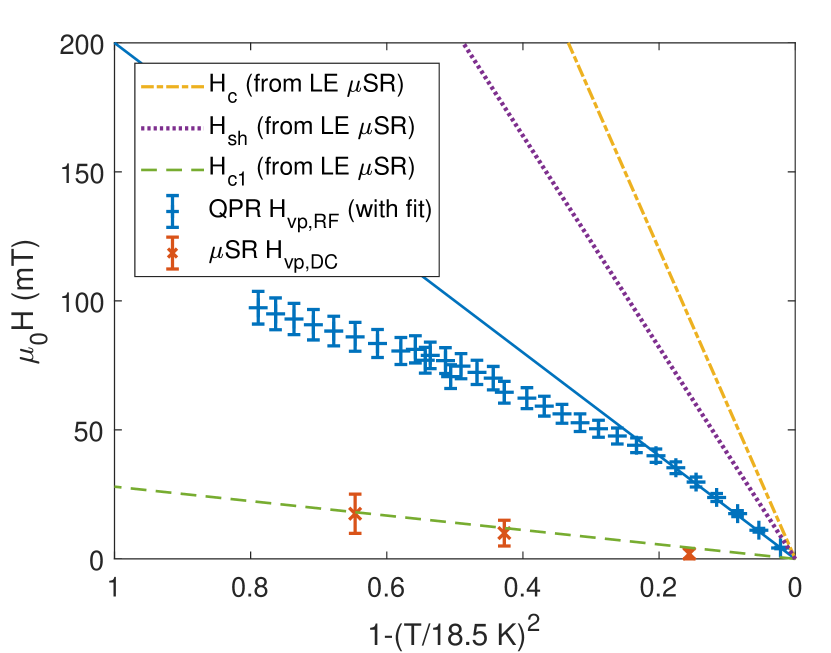
In this study the vortex penetration fields of Nb3Sn for both DC and RF magnetic fields have been measured. In addition, we derived the theoretical limits and .
The lower critical field is the field at which it is energetically favorable for flux to be located inside the superconductor instead of being expelled by Meissner currents. An energy barrier can prevent flux penetration up to the superheating field . If it is unknown whether or not there is a surface barrier, neither of these two fields can be directly measured. Here and are both obtained from the magnetic penetration depth as derived by low energy muon spin rotation. The results listed in Tab. 2 are in good agreement with data derived from low field surface impedance measurements posen2015prl . is found to be consistent with the DC field of first vortex penetration measured with surface muons.
| Method | |||||
|---|---|---|---|---|---|
| SR | - | 28(12) | 28(2) | 500(120) | 620(120) |
| QPR | 200(5) | - | - | - | - |
| 100(3) | |||||
| RF cavity | - | 29(2) | 400(80) | 600(100) |
The RF field of first vortex penetration has been measured as a function of temperature at 414 MHz using a Quadrupole Resonator. The values of clearly exceed and , see Fig. 10. This signifies that a metastable state above has been reached. However, the extrapolated value of = is about a factor of two below the predicted superheating field of this material as listed in Tab. 1. As a thermal limitation is unlikely, one may argue that the superheating field is locally suppressed, potentially by coating flaws as reported in trenikhina2017performance . Another cause of reduced vortex penetration field might be surface roughness. Recent analysis of Nb3Sn surfaces showed roughness causing local field enhancement exceeding 50 % porter2016linac . In that case, the measured should not reach the theoretical values, but be suppressed by a factor of about 1/1.5.
A possible explanation for measurement data deviating from the expected quadratic behaviour is given by vortex penetration at defects with a size of the order of the coherence length. The vortex line nucleation model (VLN) Yogi ; saito2003srf gives an heuristic formula for this limitation
| (14) |
The temperature dependence is consistent with this model for the entire range (see Fig. 7). Restricting the fit range to the same high-temperature range as used for the fit to Eq. 13 (see Fig. 7) still yields a higher adjusted -value of = for the fit to Eq. 14, compared to = for the quadratic model from Eq. 13.
VI Conclusion
In this study the maximum RF and DC fields of Nb3Sn prepared for SRF application have been measured using a Quadrupole Resonator and the muon spin rotation technique. These results have been compared to theoretical field limitations, i.e. the lower critical field and the superheating field . As both quantities depend on the London penetration depth , this material parameter has been directly measured using the low energy muon spin rotation (LE-SR) technique. The different techniques required samples of different shape and size but all samples have been prepared in the same coating chamber under same conditions.
The combined experimental results strongly confirm that Nb3Sn SRF cavities can indeed be operated in a flux free Meissner state above . It is suggested that localized vortex penetration with little or negligible preheating prevents current Nb3Sn SRF cavities to reach higher field values. This might be interpreted as a local suppression of the superheating field potentially at coating flaws as reported in trenikhina2017performance .
While in cavity tests is often extracted from low field surface impedance measurements, here LE-SR was used for the first direct measurement of this parameter on Nb3Sn prepared for SRF application. This allows to give a better determination of and than what has previously been reported. Furthermore, the strong agreement of the low energy muon spin rotation results with cavity data from posen2015prl gives confidence in the latter method of extracting material parameters from low field surface impedance measurements for future studies with different coating parameters potentially resulting in a different .
VII Acknowledgements
This work has been funded partly by a Marie Curie International Outgoing Fellowship of the European Community’s 7th Programme. The QPR part of this project has received funding from the European Union’s Horizon 2020 Research and Innovation programme under Grant Agreement No 730871. The Cornell activities of this project were supported by the U.S. Department of Energy under Award DE-SC0008431 and by the U.S. National Science Foundation under Award PHY-1549132, the Center for Bright Beams. The LE-SR measurements were performed at the Swiss Muon Source (SS), at the Paul Scherrer Institute in Villigen, Switzerland. Thanks to Gerald Morris, Bassam Hitti, Donald Arseneau, Deepak Vyas, Rahim Abasalti and Iain McKenzie from the TRIUMF CMMS support team.
References
- (1) Godeke A. Nb3Sn for Radio Frequency Cavities. Technical Report 62140, LBNL, 2006.
- (2) Transtrum M K, Catelani, and Sethna J P. Superheating field of superconductors within Ginzburg-Landau theory. Phys. Rev. B, 83(9), 2011.
- (3) Finnemore D K, Stromberg T K, and Swenson C A. Superconducting properties of high-purity niobium. Physical Review, 149(1):231, 1966.
- (4) Turneaure J P, Halbritter J, and Schwettman H A. The Surface Impedance of Superconductors and Normal Conductors: The Mattis-Bardeen Theory. Journal of Superconductivity, 4(5):341–355, 1991.
- (5) Orlando T P, McNiff Jr E J, Foner S, and Beasley M R. Critical fields, Pauli paramagnetic limiting, and material parameters of Nb3Sn and V3Si. Physical Review B, 19(9):4545, 1979.
- (6) Suter A, Morenzoni E, Garifianov N, Khasanov R, Kirk E, Luetkens H, Prokscha T, and Horisberger M. Observation of nonexponential magnetic penetration profiles in the Meissner state: A manifestation of nonlocal effects in superconductors. Phys. Rev. B, 72:024506, 2005.
- (7) Poole C. Handbook of superconductivity. Academic Press, London, 2000.
- (8) Hein M. High-Temperature-Superconductor Thin Films at Microwave Frequencies. Springer, New York, 1999.
- (9) Posen S and Liepe M. Advances in development of Nb3Sn superconducting radio-frequency cavities. Physical Review ST Accelerators and Beams, 17:112001, 2014.
- (10) Posen S, Liepe M, and Hall D L. Proof-of-principle demonstration of Nb3Sn superconducting RF cavities for high Q0 applications. Applied Physics Letters, 106:082601, 2015.
- (11) Posen S, Valles N, and Liepe M. Radio Frequency Magnetic Field Limits of Nb and Nb3Sn. Physical Review Letters, 115:047001, 2015.
- (12) Hall D L, Kaufmann J J, Liepe M, Porter R D, and Sears J. First Results from New Single-Cell Nb3Sn Cavities Coated at Cornell University. In Proc. IPAC ’17, Copenhagen, Denmark, 2017.
- (13) Posen S and Hall D L. Nb3Sn superconducting radiofrequency cavities: fabrication, results, properties, and prospects. Superconductor Science and Technology, 30(3):033004, 2017.
- (14) Junginger T, Abidi S H, Astley R, Buck T, Dehn M, Gheidi S, Kiefl R, Kolb P, Storey D, Thoeng E, Wasserman W, and Laxdal R E. Field of first flux entry and pinning strength of superconductors for RF application measured with muon spin rotation. Physical Review Accelerators and Beams, 12(032002), 2018.
- (15) Kleindienst R. Radio Frequency Characterization of Superconductors for Particle Accelerators. Ph.D. thesis, University Siegen, 2017.
- (16) Kleindienst R, Burrill A, Keckert S, Kugeler O, and Knobloch J. Commissioning Results of the HZB Quadrupole Resonator. In Proc. SRF ’15, Whistler, Canada, 2015.
- (17) Keckert S. Ph.D. thesis, to be published.
- (18) Yaouanc A and De Reotier P D. Muon spin rotation, relaxation, and resonance: applications to condensed matter. Number 147. Oxford University Press, 2011.
- (19) Schenck A. Muon Spin Rotation Spectroscopy: Principles and Applications in Solid State Physics (Adam Hilger, England, 1985).
- (20) Hayano R S, Uemura Y J, Imazato J, Nishida N, Yamazaki T, and Kubo R. Zero- and low-field spin relaxation studied by positive muons. Phys. Rev. B, 20(3):850, 1979.
- (21) Prokscha T, Morenzoni E, Deiters K, Foroughi F, George D, Kobler R, Suter A, and Vrankovic V. The new E4 beam at PSI: A hybrid-type large acceptance channel for the generation of a high intensity surface-muon beam. Nuclear Instruments and Methods in Physics Research Section A: Accelerators, Spectrometers, Detectors and Associated Equipment, 595(2):317–331, 2008.
- (22) E Morenzoni, H Glückler, T Prokscha, HP Weber, EM Forgan, TJ Jackson, H Luetkens, Ch Niedermayer, M Pleines, M Birke, et al. Low-energy sr at PSI: present and future. Physica B: Condensed Matter, 289:653–657, 2000.
- (23) Mahner E, Calatroni S, Chiaveri E, Haebel E, and Tessier J M. A New Instrument to Measure the Surface Resistance of Superconducting Samples at 400 MHz. Review of Scientific Instruments, 74:3390–3393, 2003.
- (24) Junginger T, Weingarten W, and Welsch C P. Extension of the Measurement Capabilities of the Quadrupole Resonator. Review of Scientific Instruments, 83(6):063902, 2012.
- (25) Hays T and Padamsee H. Measuring the RF Critical Field of Pb, Nb and Nb3Sn. Proceedings of the 8th Workshop on RF Superconductivity, Padova, Italy, 1997.
- (26) Biersack JP and Eckstein W. Sputtering studies with the Monte Carlo program TRIM. SP. Applied Physics A, 34(2):73–94, 1984.
- (27) Eckstein W. Computer Simulation of Ion–Solid Interactions, 1991. Springer, Berlin.
- (28) Morenzoni E, Glückler H, Prokscha T, Khasanov R, Luetkens H, Birke M, Forgan E M, Niedermayer Ch, and Pleines M. Implantation studies of keV positive muons in thin metallic layers. Nuclear Instruments and Methods in Physics Research Section B: Beam Interactions with Materials and Atoms, 192(3):254–266, 2002.
- (29) Suter A and Wojek B M. Musrfit: A Free Platform-Independent Framework for muSR Data Analysis. Physics Procedia, 30:69–73, 2012.
- (30) http://lmu.web.psi.ch/musrfit/user/html/user-libs.html.
- (31) Valente-Feliciano A-M Superconducting RF materials other than niobium: a review. Superconductor Science and Technology, 29:113002, 2016.
- (32) Tinkham M. Introduction to Superconductivity. Dover Publications, 2004.
- (33) Posen S. Understanding and Overcoming Limitation Mechanisms in Nb3Sn Superconducting RF Cavities. Ph.D. thesis, Cornell University, 2015.
- (34) Trenikhina Y, Posen S, Romanenko A, Sardela M, Zuo J M, Hall D L, and Liepe M. Performance-defining properties of nb3sn coating in srf cavities. Superconductor Science and Technology, 31(1):015004, 2017.
- (35) Porter R, Hall D L, Liepe M, and Maniscalco J T. Surface Roughness Effect on the Performance of Nb3Sn Cavities. In Proc. LINAC ’16, East Lansing, MI, USA, 2016.
- (36) Yogi, T, Dick G J and Mercereau J E. Critical rf magnetic fields for some type-I and type-II superconductors. Physical Review Letters 39.13: 826, 1977.
- (37) Saito K. Theoretical Critical Field in RF Application. In: Proceedings of the 11th Workshop on RF Superconductivity, Lübeck/Travemünde, Germany, 2003.