Symbiotic Radio: A New Communication Paradigm for Passive Internet-of-Things
Abstract
In this paper, a novel technique, called symbiotic radio (SR), is proposed for passive Internet-of-Things (IoT), in which a backscatter device (BD) is integrated with a primary transmission. The primary transmitter is designed to assist the primary and BD transmissions, and the primary receiver decodes the information from the primary transmitter as well as the BD. We consider a multiple-input single-output (MISO) SR and the symbol period for BD transmission is designed to be either the same as or much longer than that of the primary system, resulting in parasitic or commensal relationship between the primary and BD transmissions. We first derive the achievable rates for the primary system and the BD transmission. Then, we formulate two transmit beamforming optimization problems, i.e., the weighted sum-rate maximization problem and the transmit power minimization problem, and solve these non-convex problems by applying semi-definite relaxation technique. In addition, a novel transmit beamforming structure is proposed to reduce the computational complexity of the solutions. Simulation results show that when the BD transmission rate is properly designed, the proposed SR not only enables the opportunistic transmission for the BD via energy-efficient passive backscattering, but also enhances the achievable rate of the primary system by properly exploiting the additional signal path from the BD.
I Introduction
Internet-of-things (IoT), which aims at realizing ubiquitous connectivity for massive devices in a wireless manner [Atzori2010Internet, stankovic2014research], is one of the major applications of the forthcoming fifth generation (5G) and future wireless networks. Due to the exponential growth of the number of IoT devices, substantial amount of energy and radio spectrum resources is required to support such massive connections.
The lack of sufficient radio spectrum is one of the bottlenecks to the success of IoT. According to [UniEurope2016Identification], around 76 GHz spectrum resources are needed to accommodate the massive IoT connections if exclusive spectrum is allocated. While cognitive radio (CR) technology can be used to support the shared spectrum access for IoT [Liang2011Cognitive, Khan2017Cognitive, Zhang2018Spectrum], the required spectrum resource is still as large as 19 GHz [UniEurope2016Identification]. On the other hand, energy constraint is another critical issue of IoT devices. Traditional transmitters in IoT devices use active radio frequency (RF) components such as converters and oscillators, which are costly and power-consuming, thus may not be suitable for low-power IoT devices. Therefore, novel spectrum and energy efficient communication technologies need to be developed for the future IoT.
One solution to achieve energy efficient IoT is ambient backscatter communication (AmBC) [Liu2013], in which a passive backscatter device (BD) modulates its information over ambient RF signals (e.g., cellular and WiFi signals) without requiring active RF components. While suitable for passive IoT, due to the spectrum sharing nature, the backscatter transmission in AmBC may suffer from severe direct-link interference (DLI) [Wang2016Ambient], resulting in performance degradation for the BD transmission. To tackle the DLI problem, in [Guo2018Exploiting], multiple receive antennas are used to suppress the DLI, while in [Yang2017-p-], a novel BD waveform is designed with clever interference cancellation by exploiting the cyclic prefix of ambient orthogonal frequency division multiplexing (OFDM) signal. In [Zhang2018Constellation], an improved Gaussian mixture model (GMM) based algorithm is proposed to recover the BD symbols by exploiting the received signal constellation information. In [Yang-2017-p1-6], a cooperative receiver with multiple antennas is designed to decode both the primary signal and the backscattered signal. In [Darsena-2017-p1-1], the capacity of AmBC system over ambient OFDM signals with perfect DLI cancellation is analyzed. In [Kang-2017-p1-6], the AmBC system is designed to maximize the ergodic capacity of the BD by jointly optimizing the ambient RF source’s transmit power and the BD’s reflection coefficient. In [Duan2017Achievable], the sum rate of the multiple-input multiple-output (MIMO) primary system and the multi-antenna BD transmission is analyzed. In [Liu2018Backscatter], the achievable rate region of the primary and BD transmissions is studied based on a new multiplicative multiple-access channel model. The above studies all assume certain forms of cooperation at the receiver side to cancel out the DLI or suppress the DLI effect.
In this paper, we propose a novel passive IoT transmission scheme, namely symbiotic radio (SR), in which a BD is integrated with a primary transmission. In the proposed SR, the primary transmitter (PT) is designed to support both the primary and BD transmissions, and the primary receiver (PR) needs to decode the information from the PT as well as the BD. Based on different transmission rate of the BD, the proposed SR can be further divided into parasitic SR (PSR), for which the BD transmission may introduce interferences to the primary transmission, and commensal SR (CSR), for which the two transmissions benefit from each other. One of the typical applications for SR is smart home, in which a smartphone recovers the data from both its serving WiFi AP and a served IoT sensor in its vicinity.
Compared with the conventional AmBC systems, in the proposed SR, the BD transmission shares not only the radio spectrum and RF source but also the receiver with the primary system. In this paper, we consider a basic SR model consisting of a multiple-input single-output (MISO) primary system and a single-antenna BD. The PT jointly designs its transmit beamforming to assist in the primary and BD transmissions, while the PR cooperatively decodes the signals from both the PT and the BD. Thus, the BD can realize opportunistic transmission with the aid of the primary system; on the other hand the achievable rate of the primary system can be improved by properly exploiting the additional signal path from the BD.
The main contributions of this paper are summarized as follows:
-
•
First, we establish a general system model for the proposed SR and further investigate two practical setups, PSR and CSR, for which the symbol period for BD transmission is assumed to be either same as or much longer than that of the primary system, respectively.
-
•
Second, we analyze the achievable rates of the primary and BD transmissions under the two SR setups. Specifically, the achievable rate of the primary transmission is derived by treating the BD signal as an interference for PSR and a multipath signal component for CSR. After the PR cancels out the primary signal, the achievable rate of the BD transmission is obtained.
-
•
Third, transmit beamforming problems are formulated and solved, which aim to maximize the weighted sum rate of the primary and BD transmissions or to minimize the PT’s transmit power under rate constraints.
-
•
Fourth, we propose a novel optimal beamforming structure to reduce the computational complexity. Specifically, the optimal transmit beamforming vector is shown to be a linear combination of the primary direct-link channel vector and the backscatter-link channel vector.
-
•
At last, numerical examples are presented to show that for the CSR system, the BD can realize its own transmission, and meanwhile enhance the primary transmission rate by providing an additional signal path for the primary system.
| Abbreviation | Description |
|---|---|
| AmBC | Ambient Backscatter Communication |
| BD | Backscatter Device |
| CSCG | Circularly Symmetric Complex Gaussian |
| CSI | Channel State Information |
| CSR | Commensal Symbiotic Radio |
| DLI | Direct-link Interference |
| IoT | Internet of Things |
| MIMO | Multiple-input Multiple-output |
| MISO | Multiple-input Single-output |
| OFDM | Orthogonal Frequency Division |
| Multiplexing | |
| Probability Density Function | |
| PR | Primary Receiver |
| PSD | Positive Semi-definite |
| PSR | Parasitic Symbiotic Radio |
| PT | Primary Transmitter |
| RF | Radio Frequency |
| SDR | Semi-definite Relaxation |
| SIC | Successive Interference Cancellation |
| SINR | Signal to Interference plus Noise Ratio |
| SNR | Signal to Noise Ratio |
| SR | Symbiotic Radio |
| TPM | Transmit Power Minimization |
| WSRM | Weighted Sum-rate Maximization |
The rest of this paper is organized as follows. In Section II, we present the SR system model. In Section III, we derive the achievable rates of the primary and the BD transmissions for both PSR and CSR. In Section LABEL:sec:ProblemF, we formulate the weighted sum-rate maximization problem and the transmit power minimization problem. In Section LABEL:sec:solution, we present the SDR-based solutions to the formulated problems. In Section LABEL:sec:LowC, a more efficient algorithm with lower complexity is presented based on a novel beamforming structure. In Section LABEL:sec:NumR, numerical results are presented for performance evaluations. Finally, the paper is concluded in Section LABEL:sec:Conclusion.
The main notations in this paper are listed as follows: The lowercase, boldface lowercase, and boldface uppercase letters such as , , and denote the scalar, vector, and matrix, respectively. denotes the absolute value of . denotes the norm of vector . denotes the circularly symmetric complex Gaussian (CSCG) distribution with mean and variance . denotes the statistical expectation. denotes the conjugate of . and denotes the transpose and conjugate transpose of matrix , respectively. Finally, the list of abbreviations commonly appeared in this paper is given in Table I.
II System Model
Fig. 1 shows the system model of a symbiotic radio (SR) consisting of three nodes, namely the primary transmitter (PT) equipped with () antennas, the single-antenna primary receiver (PR) and the single-antenna backscatter device (BD). The PT performs multi-antenna beamforming to transmit its primary information to the PR, and at the same time enables the BD to transmit information to the PR. Specifically, the BD modulates its own information over the incident (primary) signal from the PT by intelligently varying its reflection coefficient. The SR thus shares not only the same spectrum but also the same receiver with the primary system.
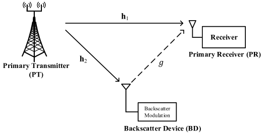
Block flat-fading channel models are considered in this paper. During each fading block, the direct-link channel from PT to PR is denoted by , where , denotes the the channel coefficient between the PT’s -th antenna and the PR’s antenna. Meanwhile, the backscatter-link channel, denoted by , is the multiplication of the forward-link channel from PT to BD, denoted by , and the backward-link channel from BD to PR, denoted by . We assume that the SR system operates in the time-division-multiplexing (TDD) mode, and the PT and the PR have perfect channel state information (CSI) of the direct link and the backscatter link. In practice, the CSI can be obtained by the training-based channel estimation scheme with two steps. First, the BD switches its impedance into the matched state, and the PT estimates the direct-link channel via channel reciprocity. Second, the BD switches its impedance into a fixed and known backscatter state, and the PT estimates the backscatter-link channel by subtracting the estimated direct-link channel component from the estimated composite channel .
III Achievable Rate Analysis
In this section, we analyze the achievable rate performance of the proposed SR. Let be the signal transmitted by the PT with symbol period , and is assumed to follow the standard CSCG distribution, i.e., . Denote the beamforming vector of the PT by . Let be the BD signal to be transmitted, with symbol period . The varies with different reflection coefficients and is assumed to be distributed111We assume that the Gaussian codewords herein to derive the maximum achievable rate of the SR. as . The backscattered signal from the BD is thus , where the power reflection coefficient controls the power of the backscattered signal by the BD. It is noticed that there is no additive noise in the BD, since its integrated circuit only includes passive components [Fuschini-2008-p33-35, Qian2017Noncoherent].
In the following, we consider two setups based on different relationships between and . One is PSR for which , and the other is CSR, for which , where is an integer and .
III-A PSR Setup
Let be the transmit power of the PT. The PR receives the backscattered signal from the BD as well as the primary signal transmitted from the PT. In the -th symbol period, the received signal at the PR, denoted by , is thus given by
| (1) |
where is the additive white Gaussian noise (AWGN) with zero mean and power , i.e., .
In practice, the direct-link signal is typically stronger222Since the analog-to-digital convertor (ADC) in the receiver often has large dynamic range (e.g., 49.9 dB for an 8-bit ideal ADC[Walden-1999-p539-550].) and the line-of-sight (LoS) pathloss due to the transmission from the BD to PR is usually within this range (e.g., 28 dB for 5m distance), the two received signals generally will not exceed the dynamic range of ADC. than the backscatter-link signal, due to the following two facts. First, the backscatter-link channel suffers from double attenuations, i.e., the forward-link channel and the backward-link channel . Second, compared to the incident primary signal, the backscattered signal from the BD further suffers from an obvious power loss due to the backscattering operation. As a result, the PR can first decode the primary signal , then cancels out the decoded signal from its received signal, and finally detects the BD signal . In the following, we analyze the achievable rate performance of such decoding scheme.
Since and have the same symbol rate, when the PR decodes the primary signal , it treats the BD signal as the background noise of which the average power is . Thus the signal-to-interference-plus-noise ratio (SINR) for decoding at the PR is given by
| (2) |
The corresponding data rate of the primary system can be written as
| (3) |
After obtaining an estimation of the primary signal , the PR utilizes the successive-interference-cancellation (SIC) technique to decode the BD signal . That is, the received primary signal component is subtracted from the received signal , yielding the following intermediate signal
| (4) |
Assuming that the primary signal is removed perfectly, we have
| (5) |
Given the primary signal , the signal-to-noise ratio (SNR) for decoding the BD signal is written as
| (6) |
Thus the average data rate of the BD transmission is written by
| (7) |
When decoding , the primary signal plays the role of fast-varying channel responses. The squared envelope of follows an exponential distribution, and its probability density function (PDF) is . Thus, the BD (i.e., backscatter-link) transmission rate can be derived as follows
| (8) |
where is the average received SNR of the backscatter link, and is defined for the exponential integral.
Remark 1.
The is a monotonically increasing and concave function of , for . This can be easily verified by its first and second derivatives.
III-B CSR Setup
In this subsection, we thus consider the CSR setup in which , where is an integer, and . Compared with the PSR setup, the BD transmission in CSR has much low rate than the primary transmission, thus it can provide an additional signal component by its scattering.
To differentiate CSR from the PSR, we let be the BD signal to be transmitted in one particular BD symbol period, which covers primary symbol periods. Thus, in the -th primary symbol period within one BD symbol period, for , the received signal at the PR is given by
| (9) |
The second signal term in (9) can be viewed as the output of the primary signal passing through a slowly varying channel . Thus the PR first decodes the primary signal by treating the BD signal as a multipath component. The equivalent channel for decoding is denoted by . Since the PR has no prior knowledge about the BD signal , a training symbol from the PT is required to estimate the equivalent channel . Given , the SNR for decoding is written as
| (10) |
With a given , the achievable rate of the direct link is thus given by
| (11) |
where we have ignored the training overhead in each BD symbol period due to large .
Thus, for sufficiently large , the average primary rate is
| (12) |
where the expectation is taken over the random variable .