ECsim-CYL: Energy Conserving Semi-Implicit particle in cell simulation in axially symmetric cylindrical coordinates
Abstract
Based on the previously developed Energy Conserving Semi Implicit Method (ECsim) code, we present its cylindrical implementation, called ECsim-CYL, to be used for axially symmetric problems. The main motivation for the development of the cylindrical version is to greatly improve the computational speed by utilizing cylindrical symmetry. The ECsim-CYL discretizes the field equations in two-dimensional cylindrical coordinates using the finite volume method . For the particle mover, it uses a modification of ECsim’s mover for cylindrical coordinates by keeping track of all three components of velocity vectors, while only keeping radial and axial coordinates of particle positions. In this paper, we describe the details of the algorithm used in the ECsim-CYL and present a series of tests to validate the accuracy of the code including a wave spectrum in a homogeneous plasmas inside a cylindrical waveguide and free expansion of a spherical plasma ball in vacuum. The ECsim-CYL retains the stability properties of ECsim and conserves the energy within machine precision, while accurately describing the plasma behavior in the test cases.
keywords:
Particle in cell (PIC), Semi-implicit particle in cell, Exactly energy conserving, Axis symmetry cylindrical problem1 Introduction
Particle In Cell (PIC) algorithms are widely used to study natural and laboratory plasmas using fully kinetic description [1, 2]. In a typical PIC algorithm, particles and fields are advanced alternatively in a cycle. Particles are moved with the fields obtained by interpolation from a grid and the particle information is then used to project the sources of the fields, i.e. current and charge, onto the grid advancing the field values in time. This alternation of particle movement and field solution is the typical feature of explicit PIC codes. Explicit PIC codes are straight-forward to design and lead to extremely efficient parallel implementations. As such, explicit PIC codes are always among the most successful applications on new supercomputers.
However, explicit PIC codes suffer from a scale limitation [1, 2]: the alternative field and particle solver approach of the explicit cycle leads to two limitations: the time step needs to resolve the electron plasma frequency and the grid spacing need to resolve a multiple of the Debye length (the multiple depends on the interpolations scheme). Plasma problems are typically multi scale, with ions responding on much longer and slower scales than electrons. The need for explicit PIC codes to resolve all electron scales, led to development of implicit PIC methods to overcome this difficulty.
Implicit methods retain the coupling of particle motion and field solution at each time step. They are no longer done separately in sequence but rather become part of an iteration. This coupling is non-linear and it requires the use of non-linear solvers [3, 4].
However, when the coupling of particles and fields is linearized, the iteration becomes linear and typically based on Krylov solvers: in this case the methods are considered semi-implicit. This semi-implicitness should not be confused with the methods that solve implicitly only the field equations but still remain explicit in alternating particle mover and field solver [5]. This class of algorithms are designed to overcome the speed of light limitation in the electromagnetic waves and are not considered here.
All implicit and semi-implicit PIC codes enable the user to use larger time steps and grid spacing, an advantage when dealing with multi scale problems where the electron physics need not be represented in detail but still needs to be captured in macroscopic terms [6]. For these algorithms, the electron response to large scales is captured correctly but the small scale fluctuations (e.g. Langmuir waves) are damped [7, 8]. While fully implicit methods require an advanced arsenal of non-linear solvers, supported by efficient preconditioning [9] to reduce the number of iterations, semi-implicit methods can use more standard linear solvers.
Semi-implicit methods were the first to be deployed in large practical applications. The literature reports two lines of semi-implicit codes: the direct implicit method [10] and the moment implicit methods [7]. The most modern implementations are, respectively, LSP [11] and iPic3D [12]. Among the semi-implicit algorithms, we have recently developed a new algorithm called ECsim [13, 14, 15] that adds one more desirable property to the previous semi-implicit schemes: energy conservation.
ECsim uses a new tool to represent the linear response of the plasma to the fields: the mass matrix [16, 13]. The use of a new mover allows the introduction of this linear formulation without requiring any linearization: the result is that ECsim is exactly energy conserving. This has two aspects. First, there is a formal analytical energy integral that has been derived to show energy conservation by the scheme. Second, when coded into a computer implementation, energy is conserved to machine precision, a powerful debugging feature as well as a desirable physical property [13].
ECsim has the extra computational complexity of requiring the computation of the mass matrix by interpolation from the particles. The extra cost of this operation was evaluated in Ref. [15]. Compared with other PIC codes, ECsim requires more memory to store the mass matrix and more computational costs to compute it. When compared with specifically with the moment implicit methods, such as iPic3D [12], ECsim increases the number of operations needed to project particle information to the grid, as required to compute the mass matrix. However, this increase is in part compensated by the reduced complexity of the mover. The cost per cycle increases by a factor of 2 to 4 but it is more than compensated by the ability to use larger time steps allowed by energy conservation [15]. The increase in memory is not significant as it does not increase the particle memory, by far the overwhelming majority of the memory used: by comparison, the additional memory required to store the mass matrix is not significant.
In many applications, there is an easy way to reduce the cost: use the intrinsic symmetry of the problem. Many experiments and natural processes have a natural axis of symmetry and cylindrical symmetry allows one to treat them as two-dimensional problems. Symmetry reduces the computational effort by reducing the dimensionality, enabling higher spatial resolutions or reducing the computational cost. We have implemented a new version of ECsim in cylindrical coordinates (hereinafter ECsim-CYL) for these axially symmetric cases. This new version, analogously to the original ECsim code, conserves the total energy exactly and retains the same stability properties.
Cylindrical symmetry has been used in several previous explicit and even semi-implicit codes, based on simpler algorithms that do not conserve energy exactly. In the explicit approach, cylindrical symmetry is described in textbooks [1] and has been applied in production codes [17]. Also for the moment implicit approach a cylindrical version was developed [18], based on the same formulation of the implicit moment method [8] in cartesian geometry, at the basis of Venus, Celeste and iPic3D: this method does not conserve energy exactly.
However, ECsim-CYL is the first semi-implicit code which implements the Energy Conserving Semi Implicit algorithm in cylindrical coordinates and is the first semi-implicit code that conserves energy.
More recently, general curvilinear geometry codes have been developed both for explicit [19, 20] and for implicit codes [21].
ECsim-CYL has been developed in C++ and uses MPI for parallel communications. It shares the infrastructure (particle communication, particle-to-grid interpolations, etc.) of the fully 3D Cartesian ECsim [15] and has a similar scaling behavior and performance.
The paper is organized as follows. In section 2, we describe the algorithm used in the ECsim-CYL implementation regarding the discretization of the field equations using cylindrical coordinates and the implementation of the particle mover. In section 3, we test the accuracy of both the field solver and particle mover. In section 4, we test the ECsim-CYL results against the analytical formula regarding the plasma wave in an homogeneous plasma inside a cylindrical waveguide. This is followed by the test results of ECsim-CYL in the simulation of homogeneous expansion of a plasma sphere in vacuum with different spatio-temporal resolution and ion mass ratio in section 5. In Section 6, we summarize the results and present the conclusions.
2 Description of the algorithm
The scheme and the main loop of the code are identical to the ones of ECsim described in [13, 15]. The interpolation of the current densities from the particles to the grid and the calculation of the mass matrices are performed in the same way as in Cartesian coordinates. The only thing to keep in mind is that now the volume of the individual cells is not constant in space, but depends on the radial position of the cell.
The particle initialization is, however, performed in a slightly different manner. In order to have an homogeneous density (if that is what’s desired), the charge in each cell has to be proportional to its volume. This can be achieved using a different number of particles per cell or assigning a weight to the particles depending on which cell they belong to. Let’s assume we want to have a charge density . In the first case, we define the number of particles in the first cell and then the charge of each particle is given by: , where is the volume of the first cell (at ). Then the number of particles in the cell (with volume ) is computed as . In the second case, the number of particles is the same for all cells, and the charge of the particles depends on which cell they are at the beginning of the simulation: all particles initially in the cell will have a charge according to .
In order to have a significant number of particles in all the cells, more particles are needed overall in the version of the algorithm in which all the individual particles are assigned the same weight. Both options are available in ECsim-CYL and both of them have given similar results in the test cases.
The main differences between ECsim-CYL and the Cartesian version are to be found in the particle mover and in the discretization of the field equations, which are described in detail in the next subsections.
2.1 Field solver
The field equations are the same as in the Cartesian version, however the discretization technique used is different. While in ECsim we used the Finite Difference method, here we have employed a Finite Volumes technique to integrate the equations given by Eqns. (1) and (2):
| (1) | |||
| (2) |
where is the electric field (defined on the nodes), the magnetic field (defined on the cell centers) and is the decentering parameter (which has to be 0.5 to conserve the energy). is the implicit current (defined on the nodes) which is computed through the mass matrices: . A detailed description can be found in [13].
We have already stated above that to discretize Eqns. (1) and (2) we use the Finite-Volume method [22]. We integrate each term over the control volume, i.e., the volume of the cell () for Eq. (1) and the volume of the node () for Eq. (2). Let’s denote with (i,j) the indices of the cell/node in the r and z direction. Then the control volumes are, respectively
| (3) | |||||
| (4) |
Integrating Eq. (1) and Eq. (2) over the corresponding control volume we have
| (5) | |||
| (6) |
where we have made use of the result that, for any magnitude defined on the nodes, the integral over is
| (7) |
and the same for the magnitudes defined on the centers and the integral over .
To compute the integral of we can use the fact that
| (8) |
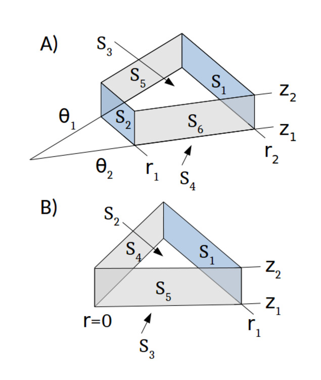
In the following we will omit the super index for simplicity. Using the scheme shown in Fig. 1 (A) we can expand the integral of the curl as follows
where , and are the unitary vectors in the , and directions. After integrating over each surface we arrive at the following expressions:
| (9) | |||||
| (10) | |||||
| (11) |
where
| (12) | |||||
| (13) | |||||
with . The same can be applied to the curl of apart from the case with r=0, which has to be treated separately. Using the scheme shown in Fig. 1 (B) and following the same procedure we can obtain:
| (14) | |||||
| (15) | |||||
| (16) |
With this procedure, (which is defined on the cell centers) can be computed from the values of on the nodes. And similarly, is defined on the nodes and is computed from the values of on the cell centers. This way, every term in Eq. (2) is defined on the nodes and the ones in Eq. (1) is defined on the cell centers. In addition, this discretization ensures the conservation of the total energy.
2.2 Particle mover
We employ a combination of the ECsim mover described in [13] with the Boris mover in cylindrical coordinates [18]. Once the electric and magnetic fields at time have been computed, we advance the particles as in Cartesian coordinates. First, we build the position and velocity of the particles in Cartesian coordinates using the values in cylindrical coordinates: and . And then we operate as in the Cartesian case:
| (17) | |||||
| (18) | |||||
| (19) |
where , are the electric and magnetic fields at time at the particle position. is the time step and is the rotation matrix given by:
| (20) |
where , with and the mass and charge of the particle. After this we have the new position and velocity : and .
Then, we rotate the particle back to the plane , as is done in the Boris mover [18].
| (21) | |||||
| (22) |
The velocity and position in cylindrical coordinates are obtained applying this rotation to the vectors in Cartesian coordinates:
| (23) | |||||
| (24) |
Note that by the end of the mover step the azimuthal component of the position is zero, so the particles are always in a plane. This procedure conserves the energy and does not spoil the stability features of the original algorithm in Cartesian coordinates.
3 Accuracy of the field solver and particle mover
A very important practical concept is the order of accuracy of each component of the algorithm. The order of accuracy has obviously a practical impact on the fidelity of the solution but in a particle in cell code this aspect is complicated by the noise produced by the particles. One should really consider ensemble of simulations and discuss convergence in statistical terms. However, for practical purposes the order of accuracy is a powerful tool for the verification of a code. For ECsim, energy conservation is itself an extremely useful debugging tool. As the code was being developed, we experimented how sensitive energy conservation is to any bug in the code, from communication issues to more traditional coding errors.
Order of accuracy can be an additional tool to identify implementation errors in each component of the code [24]. In order to determine the accuracy of the cylindrical implementation, code results are compared with reference solutions, either from the Matlab function ODE45 or from the analytical calculations. Detailed parameter scans have been conducted by varying time steps and computing the errors with respect to the reference solution. Below we show that both particle mover and field solver have 2nd order accuracy.
3.1 Particle mover
The trajectory of a particle with mass and charge in a non uniform radial electric field and axial magnetic field is investigated. We assume that both and are linear with the radial coordinate :
| (25) | |||
| (26) |
where and are the values of the fields at and and are constants which determine the linear dependence of the fields. The rest of the components of the electric and magnetic fields are assumed to be zero.
The particle is advanced in time using Eqns. (23)–(24). Then the result is compared with the solutions obtained by integrating the equations of motion in cylindrical geometry with the Matlab function ODE45. The tolerance for the ODE45 solver is set to machine precision, so we can consider its result as the exact solution. Figures 2 and 3 show an example of the comparison between the ECsim-CYL mover and the Matlab solutions. In particular the evolution in time of the radial coordinate and the radial velocity are shown for two different time steps. In both cases the results from the code are in excellent agreement with the reference solution.

We have also carried out tests where we vary the time step used to compute the particle trajectories with the ECsim-CYL mover, in order to study the influence on overall accuracy of this parameter. The error on the radial position was computed as:
| (27) |
where is the variance. , and is the average value, . The same definitions hold for the error on the particle radial velocity. Results are shown in Fig. 4, in which and are plotted for different values of . The error on the particle orbit increases quadratically with , thus confirming that the mover is second order accurate in time.

3.2 Field solver
The cylindrical electromagnetic wave propagation in vacuum is studied with a one-dimensional version of the field solver presented in section 2.1. We investigate the TE (Transverse Electric, or ) mode. The problem presents an analytical solution, given by:
where denotes the Bessel function of the first kind of order 0, the Bessel function of the first kind of order 1 and , with the zero of the Bessel function of the first kind and order 1 and the length of the domain. Therefore in order to analyze the propagation of the electromagnetic fields, the following initial conditions for the electric and magnetic fields are considered in the code: , with and . A comparison between analytical and numerical solutions is reported in Fig. 5, which show the fields as a function of at different times. The plots are obtained choosing the size of the domain equal to , using 128 cells and a time step equal to . The duration of the runs is . The curves are in excellent agreement.


The numerical error introduced by the code has then been computed after the numerical solution was advanced until a chosen time step . The error on a given field is computed as:
| (28) |
where the superscripts an and num refer to the analytical and numerical solutions at . The quantities indicate the Euclidean norm, computed as
| (29) |
where the summation is over the radial points into which the domain is discretize. Results are presented in Fig. 7, which shows the error introduced by the code for different values of , assuming constant (quantities in dimensionless units). Both in the case of and , the error varies quadratically with indicating that also the field solver is a second order scheme in time.

4 Plasma wave spectrum in homogeneous plasma
This test case consists of an homogeneous electron-positron plasma which completely fills a cylindrical waveguide. Electrons and positrons have a Maxwellian distribution for the velocities and they are at the same temperature. This situation is well known and according to electromagnetic theory, in a cylindrical waveguide filled with an homogeneous plasma there is one solution of the Maxwell’s equations called the "magnetic mode" or "H wave" [25]. These waves have a dispersion relation given by
| (30) |
where is the cutoff frequency.
| (31) |
In Eq. (31) is the plasma frequency, the root of the Bessel functions , the speed of light and the radius of the guide. In our case, since the system is axially symmetric, only the wave with exists. In order to validate the code, we have designed a case which reproduces this situation and we have analyzed the spectra.
The size of the domain is determined by its radius and its length . We have cells in direction and in direction. We have used 1 000 000 particles with a thermal velocity of , 500 000 electrons and 500 000 positrons. Both sets of particles are initialized randomly in the entire domain. The time step is and we have run the simulation for 5 000 cycles (25 ). We have assumed that the waveguide is a perfect conductor, hence at the outer boundary conditions both the tangential electric components and and the derivative of the normal electric component are nil.
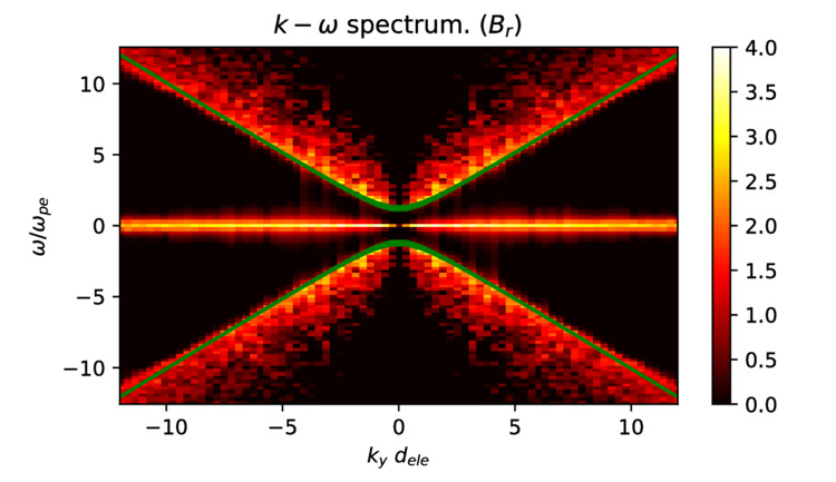
In Fig. 8 we show the spectrum of the simulation together with the dispersion relation given by Eq. (30) for (green line). As the abscissa we have the number in the direction in units of ion skin depth () and as the ordinate the frequency in units of inverse of the plasma frequency (). The simulation results and the theory are in very good agreement. As should be expected, at large and , the numerical discretization of the operators introduces a (second-order, as shown above) truncation error and the results from the simulations start to diverge slightly from the analytical solution.
5 Free Expansion
In order to further test the accuracy and capability of the ECsim-CYL implementation, we have investigated homogeneous expansion of a plasma sphere in vacuum. The test covers the following three areas: 1) How ECsim-CYL preserves spherical symmetry with the use of cylindrical coordinates, 2) How ECsim-CYL conserves total energy of the system, and 3) How ECsim-CYL describes ambipolar plasma diffusion with respect to charge separation, self-consistent ambipolar electric field, and change in velocity distribution of ions and electrons. The underlying mechanism of ambipolar plasma diffusion lies with the difference in the particle velocity between lighter electrons and heavier ions. Initially, electrons will expand faster than ions due to their lighter mass and faster velocity for the same temperature. This leads to charge separation between electrons and ions, which in turn generates an electric field. The spatio-temporal profile and the magnitude of this electric field is then adjusted by the plasma motion as the electric field slows down the rate of electron expansion and accelerates the rate of ion expansion until the rate of ion and electron expansion is equalized. This phenomenon, called ambipolar diffusion, is well known in plasma physics and further details can be found in many standard textbooks [26].
| Case | # cells | / | Cycles | # part | CPU hours | |||
|---|---|---|---|---|---|---|---|---|
| A | 25 | 0.2 | 10.0 | 0.4 | 100 | 0.08 | ||
| B | 25 | 0.1 | 5.0 | 0.2 | 200 | 0.65 | ||
| C | 25 | 0.05 | 2.5 | 0.1 | 400 | 5.47 | ||
| D | 25 | 0.02 | 1.0 | 0.04 | 1000 | 88.33 | ||
| A-3D | 25 | 0.2 | 10.0 | 0.4 | 100 | 3.97 | ||
| A-1836 | 1836 | 0.2 | 10.0 | 0.4 | 857 | 0.70 | ||
| D-1836 | 1836 | 0.02 | 1.0 | 0.04 | 8570 | 759.81 |
Table 1 summarizes the simulation conditions used in the test. For a majority of the tests, we have used light ions with with the same temperature for electrons and ions. This reduced ion mass is used to speed up the computation time compared to the realistic ion mass of . Later, we will present the result for the hydrogen ion with the mass of and compare the results with the reduced mass case of . The simulation begins with an initial homogeneous plasma inside a sphere with a radius of with Maxwellian distribution for ions and electrons with an electron thermal velocity of and and an ion thermal velocity of where is the speed of light. It is noted that the ECsim-CYL like ECsim and iPic3D utilizes the normalized unit with c = 1.
The initial charge particle density is set inside a sphere for or , where is the ion inertial length, is the ion plasma frequency, is the electron Debye length, and is the electron plasma frequency.
The radius and length of the cylindrical simulation domain are and . As for the time step, the Courant-Friedrichs-Lewy (CFL) condition of is utilized for all cases in Table 1. As a semi-implicit particle code, this CFL condition is the only numerical constraint of ECsim-CYL regarding the size of time step[6, 13]. In addition, the total number of particles in each case is chosen to keep the particle density per cell constant during initialization, while all simulation particles have the same charge except for the sign. Since all the particles have the same weight, to achieve a uniform charge distribution the number of particles per cell depends on the volume of each cell, which depends on the radial distance to the axis.
The calculations have been done using 16 Intel Xeon E5-2643 3.30 GHz cores. In some of the smaller cases only 2 or 4 cores have been used. The amount of CPU hours of each case is the results of the number of cores used multiplied by the total runtime.
5.1 Spherical symmetry
Since the code must reproduce the plasma dynamics independent of its coordinate choice, we conducted homogeneous expansion of a plasma sphere in vacuum with the 3D Cartesian ECsim and with ECsim-CYL. Fig. 9 compares the electron density profiles on XY plane at from the case A-3D using ECsim and the case A using ECsim-CYL, which shows good agreement between the two with well preserved spherical symmetry. As shown in Table 1, the case A-3D run using ECsim utilizes cells with particles. In comparison, the case A using ECsim-CYL utilizes cells with particles. These two runs use the same time step of and the same spatial resolution in the radial and vertical direction of . In terms of computational cost, the case A run took only 0.08 CPU hours to complete 100 cycles compared to 4 CPU hours for the case A-3D, an improvement by a factor of 50. This improvement in speed is related to the reduction in dimensionality by taking an advantage of axisymmetric condition, validating our motivation to develop the ECsim-CYL. This gain in speed will be even more significant with increasing simulation scale as we estimate that the ECsim-CYL would be about 500 times faster than the ECsim in the case of 250 x 500 grid resolution.
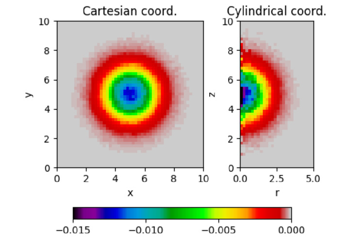
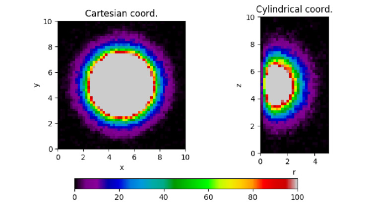
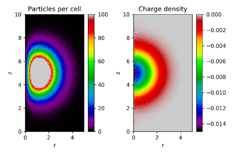
It is also noted that there are some differences between the results of ECsim-CYL and ECsim as understanding these differences would be important in utilizing ECsim-CYL. The electron density profile from ECsim-CYL in Fig. 9 exhibits significant noise near the axis, especially for the 1st cells in the radial direction. This is expected for a cylindrical code as the volume of the cell becomes very small near r=0 and contains significantly fewer particles per cell as shown in Fig. 10. On the other and, the particle number per cell increases with increasing radius in ECsim-CYL. Outside r=1, the particle number density becomes comparable between the ECsim run and the ECsim-CYL run leading to a good agreement between them despite the fact that ECsim-CYL utilizes 100 times less particles. As such, the ECsim-CYL is an excellent tool to investigate the plasma dynamics of the axisymmetric system where the main region of interest is away from the axis of symmetry. On the other hand, caution must be taken to ensure the accuracy of results near the axis for a system where the accurate description of plasma motion near the axis is important. One way to mitigate the axis problem is to increase the number of cells in the simulation. As shown in Fig. 11 from the case D run, the use of a large number of cells greatly reduces the noise near the axis and provides improved spatial profiles albeit at a computational cost.
5.2 Energy Conservation
The next test is the energy conservation of ECsim-CYL. Previously, we developed the ECsim code to improve the stability of semi-implicit code at large spatial scales by implementing energy conserving algorithm.

We tested the energy conservation of ECsim-CYL for different grid sizes and time steps and the results are shown in Figure 12 from the cases in table 1. Like the ECsim code, ECsim-CYL conserves the energy down to the numerical accuracy of the solver for all cases. In this case, the solver tolerance is set down to machine precision and energy conservation is equal to machine precision. For all practical purposes, the energy conservation is exact, as has been proven mathematically, regardless of the dimensionality of the problem [13]. The cylindrical implementation retains this same property as in the Cartesian case.
The energy conservation has three benefits. First, energy is a key conserved quantity in Nature and it is clearly desirable to preserve the energy conservation in numerical algorithms. Second, non-conservation of energy can lead to numerical instability, a condition where spurious energy can feed erroneous growth of modes that do not exist. Imposing energy conservation removes this risk. Third, the energy conservation provides a simple scalar quantity to check the accuracy of the code (i.e. total energy) and can be utilized as a powerful debugging tool.
5.3 Divergence Conservation
The choice of finite volume operators reported in Section 2.1 is second order accurate and leads to exact conservation as shown above because the differential operators are integrated over finite volumes and the result is expressed via a surface integral. The conservation properties follow from the fact that the surface integral is identical for both cells sharing the same surface. This property comes to a cost: the operators are not mimetic [27], i.e. the known null properties of combined operators, namely the divergence of the curl, are not satisfied exactly. This can lead to numerical errors in code results. Figure 13 reports the norm of the error in the two divergence conditions in Maxwell’s equations.
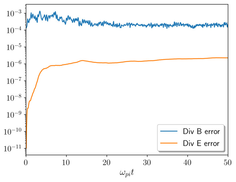
The equation for B (eq.(1)), advances the magnetic field with the curl of the electric field. If the operators were mimetic, the divergence of the magnetic field would always be exactly zero. Since the operators are not mimetic, this leads to the divergence error shown in Fig. 13, defined as
| (32) |
The normalization is typical in the evaluation of the divergence error for B and uses the norm of the curl, essentially the current. In comparison, the error in the Gauss theorem is defined as
| (33) |
with normalization using a total charge of one species in the system (we use positive ions since the total charge including electrons would be zero because of charge neutrality). In the present case, both errors saturate quickly in time at a level between in the case of magnetic field and in the case of electric field. Considering very weak magnetic fields in the case of spherically symmetric plasma expansion, we find that the errors related to non-mimetic operators are small and would not affect the accuracy of the simulation.
5.4 Ambipolar diffusion
As previously discussed, free expansion of a plasma sphere in vacuum will induce charge separation between ions and electron, self-consistent ambipolar electric fields and change in particle velocity distribution. Fig. 14 shows the net charge density profile for three different times during the plasma expansion, at , , and for the cases A and D, showing good agreement between the two cases for all three times. While the spatial profile of charge separation is better defined in the high-resolution case of D, the charge separation is still clearly visible in the case of A where the spatial resolution is 10 times coarser in exchange for 1,000 times faster computation time.
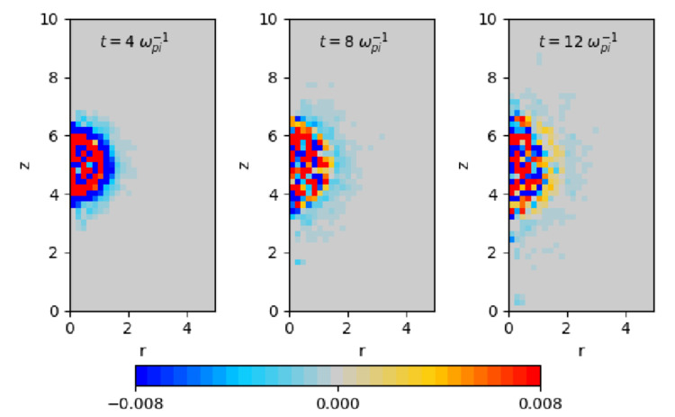
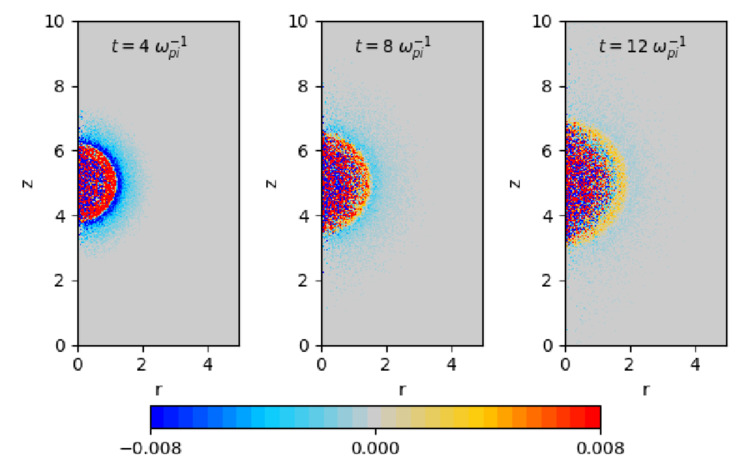
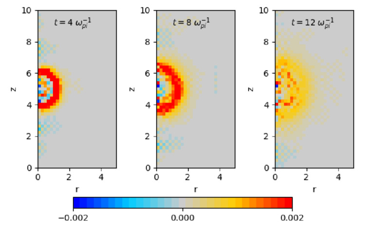
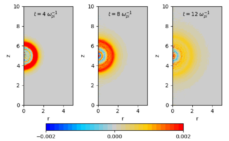
Fig. 15 shows the spatial profile of electric field in the radial direction for , , and for the cases A and D. Positive values, marked in red, indicate the electric field pointing radially outward and negative values, marked in blue, are for the radially inward electric field. Similar to the net charge density profile shown in Fig. 14, the ECsim-CYL results show the ambipolar electric field for both cases of A and D. The comparison is positive. There re of course differences and the details are noisier and less defined in the low resolution run, but one critical aspect is very similar: the extension of the expansion is remarkably similar. Despite a big difference in spatial resolution and computation speed, the low resolution run is still capable of capturing the essential nature of the expansion. Especially remarkable is the correct sign and location of the outermost double layer made of a positive shell surrounded by a negative halo (see Fig. 14). This feature is present in all resolution. Additionally, the radial location of these features is correct even at low resolution.
| electrons | N/A | N/A | N/A | ||
|---|---|---|---|---|---|
| ions | N/A | N/A | N/A | ||
| A () | electrons | ||||
| ions | |||||
| B () | electrons | ||||
| ions | |||||
| C () | electrons | ||||
| ions | |||||
| D () | electrons | ||||
| ions | |||||
| A-1836 () | electrons | N/A | N/A | N/A | |
| ions | N/A | N/A | N/A | ||
| A-1836 () | electrons | ||||
| ions | |||||
| D-1836 () | electrons | N/A | N/A | N/A | |
| ions | N/A | N/A | N/A | ||
| D-1836 () | electrons | ||||
| ions |
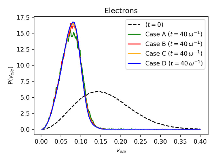
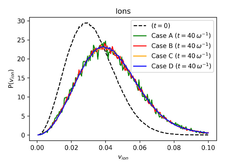
The role of self-consistent ambipolar electric fields is to balance the rate of expansion for electrons and ions by transferring energy from lighter electrons to heavier ions, thus modifying their velocity distribution. Fig. 16 shows the velocity distribution of electrons and ions at and for case A, B, C and D. At , the electron and ion distribution are given as Maxwellian with the same temperature. As the plasma expands, the difference in electron and ion mass and their respective velocity leads to the charge separation and the ambipolar electric fields as shown in Fig. 14 and Fig. 15. As shown in Fig. 16, the electric field slows down the electrons and shifts its velocity distribution toward lower velocities. For ions, the electric fields accelerate ions and shift its velocity distribution toward higher velocities. It is noted that the good agreements are observed for all four cases despite their difference in spatial resolution and computation time. In addition, the Table 2 shows the total kinetic energy of electron and ions at with their respective drift velocity in , , direction for case A, B, C and D, where , , are three orthogonal directions of spherical coordinates. As expected for the spherical expansion, the plasma drift velocity is mostly in the radial direction with small fluctuations in and direction. Furthermore, the total energy of the system is well preserved even though significant energy transfer occurs between electrons and ions via ambipolar electric fields. Note that small differences in the kinetic energy is due to the difference in stored energy in electric and magnetic fields in the system, which is 3-4 orders of magnitude smaller than the kinetic energy in the system. Table 2 further validates that the ECsim-CYL properly describes ambipolar plasma diffusion leading to equalized ion and electron drift velocity over a wide range of spatial resolution.
5.5 Ion Mass Ratio
As additional tests to validate the ECsim-CYL implementation, we have repeated the case A and D with an ion mass of while keeping the electron mass the same. As shown in Table 1, the case A-1836 uses the same spatial resolution as the case A, and the case D-1836 uses the same spatial resolution as the case D. It is noted that the ion mass of represents hydrogen ions and known as a realistic ion mass. Same as the cases A and D, the initial charge density of a homogeneous plasma sphere for the cases A-1836 and D-1836 is set for the sphere radius to with the electron thermal velocity of . Due to the increased ion mass, the ion thermal velocity is reduced from to or by a factor of sqrt(1836/25) to keep the ion temperature equal to the electron temperature. The radius and length of the cylindrical simulation domain are kept the same when normalized by ion inertial length with R = 5 di and L = 10 di. Also, we utilized the same CFL condition of .
.
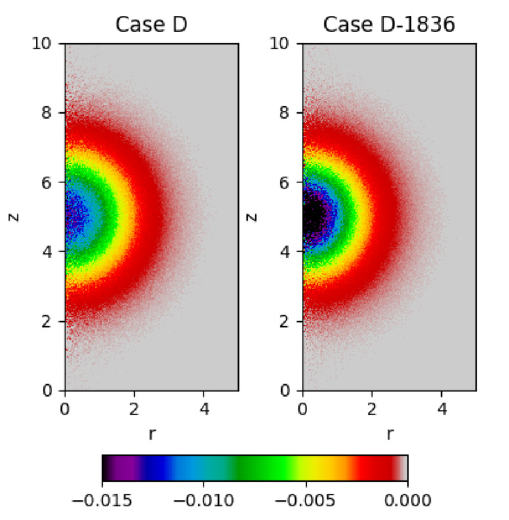
Here we note two main changes in the simulation related to the change in ion mass. The first is the reduced ion velocity for the same plasma temperature. Heavier and slower ions will require longer time to expand outward. While the ambipolar electric fields will still accelerate ions by transferring energy from electrons, the outward ion drift velocity will be reduced by or compared to the ion mass of . This corresponds to the increase in simulation cycles by times for the plasma to reach the same radial extension. Fig. 17 compares the electron charge density profile for the case D at and for the case D-1836 at , showing a slower rate of plasma expansion for heavier ions. In comparison, the time step for the cases A-1836 and D-1836 is determined by the CFL condition, thus there is no need to adjust the time step as long as the same value of and are used. The second change related to the ion mass is the ratio between ion inertial length and electron Debye length. For a fixed ion inertial length, the Debye length will decrease by a square root of ion mass, corresponding to an initial plasma sphere radius of for the cases of A-1836 and D-1836 instead of for the cases of A and D.
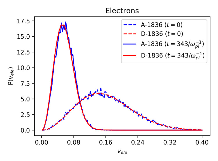
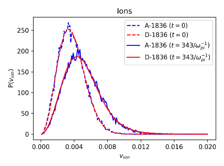
Fig. 18 shows the velocity distribution of electrons and ions at and for the cases A-1836 and D-1836. As in Fig. 16, a good agreement between these two cases is observed for the electron and the ion velocity distribution despite their difference in spatial resolution and computation time. It is noted that with the increased in ion mass, the peak of electron velocity distribution occurs for at from at . In comparison, the peak of electron velocity distribution shifts to at from at in the case of , as shown in Fig. 16. As for ions, the peak of ion velocity distribution shifts to at from at in the cases , while the peak shift from to in the cases of . In addition, the Table 2 shows the total kinetic energy of ions and electrons at with their respective drift velocity in , , direction for cases A-1836 and D-1836. These results indicate that more energy is transferred from electrons to ions via ambipolar electric fields with increased ion mass. The results from the Fig. 17, Fig. 18 and the Table 2 shows ECsim-CYL properly simulates ambipolar plasma expansion for a realistic ion mass of while using the same time step and spatial resolution of reduced ion mass cases of .
5.6 Grid resolution with respect to Debye length
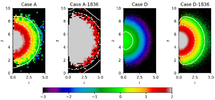
One of the noteworthy findings from the free expansion test is the robustness of ECsim-CYL as it accurately simulates the ambipolar diffusion even for a very coarse spatial resolution. Fig. 19 shows the ratio of spatial resolution () and electron Debye length for cases A and D at and cases A-1836 and D-1836 at in logarithmic scale with the solid white line indicating the isocontour of . In the case of D, the spatial resolution is sufficient to resolve the electron Debye length except for the core region inside the white line. On the other hand, the electron Debye length is not resolved in most of the simulation domain in the case of A and D-1836. The spatial resolution is even coarser in the case of A-1836 where the spatial resolution is more than 10 times the electron Debye length in most of the system. The results in Fig. 19 indicate that the ECsim-CYL can provide the accurate description of ambipolar effects even when the spatial resolution is many times larger than the Debye length.
Since the ambipolar diffusion is one of the critical conditions that must be satisfied in simulation to properly describe the plasma motion, this result offers a tantalizing prospect of a full fusion device simulation using ECsim-CYL. Typical plasma parameters for a fusion reactor are the following: a reactor size of meter in linear dimension, a plasma density of cm and a plasma temperature of keV leading to an electron Debye length of cm. This large difference between the system size and the Debye length is one of the major challenges in simulation of a full-scale fusion device if one needs to resolve the electron Debye length to include accurate description of ambipolar diffusion in the system. For example, in a fully three dimensional reactor configuration without a symmetric axis such as tokamaks and stellarators, this requirement translates to a very large number of cells on the order of 100,000 x 100,000 x 100,000 cells or cells. In comparison, if the system possesses axisymmetry and is free from plasma instability that can break the symmetry, one can utilize a reduced dimension code such as ECsim-CYL to greatly reduce the required number of cells. Additional reduction in a required cell number may be achieved by taking an advantage of ECsim-CYL which can properly describe the critical ambipolar diffusion of the plasma system with the use of spatial resolution much larger than the electron Debye length. In the case where spatial resolution of 10 Debye lengths is adequate, the ECsim-CYL can simulate an entire fusion reactor with the cell size of 5,000 x 5,000 or cells which is well within the numerical capability of modern high performance computing facilities. Another advantage of ECsim-CYL is that the size of time step is controlled by the CFL condition. Therefore, a bigger time step can be used for a larger grid size, which is desirable for a large system domain since the particle travel time across the system is significant.
6 Conclusions
We have presented ECsim-CYL, a PIC code in cylindrical coordinates for axially symmetric simulations based on the previously developed ECsim code. We have discussed the discretization used to numerically solve the field equations in cylindrical coordinates and the strategy for moving the particles. We have studied the accuracy of the particle mover and the field discretization, showing that both the field solver and the particle mover are second- order accurate. In section 4 and 5, we have tested the ECsim-CYL code using two well-known problems in plasma physics: the plasma wave spectrum in an homogeneous plasma inside a cylindrical waveguide and the homogeneous expansion of a plasma sphere in vacuum. In the first case, the results given by the code show a good agreement with the analytical formula. While the second case, free expansion of a plasma sphere, is more complex and without direct analytical comparison, it provides an excellent example to asses the practical advantages of ECsim-CYL. The test results show that the ECsim-CYL implementation accurately preserves the spherical symmetry, conserves the total energy of the system, and accurately describes the ambipolar effects over a wide range of spatio-temporal resolution. In particular, we have shown that the ECsim-CYL properly simulates the critical energy transfer between electrons and ions via self-consistent electric fields behind the ambipolar diffusion even if the Debye length is poorly resolved with the grid spacing exceeding 10 times the Debye length in the simulation domain, a key point of semi-implicit approach.
The new ECsim-CYL code thus opens exciting opportunities for future research in plasma simulation. Using an axial symmetry, the computational time is dramatically reduced when compared with the 3D Cartesian description. Combined with the relaxed resolution constraint in grid spacing and time step of semi-implicit code, this feature opens the door to global simulations of laboratory experiments and natural plasmas in a fully kinetic approach. Specifically, the ECsim-CYL may open the door to global simulations of fusion and astrophysical plasma systems where the gap in scales between the Debye length and the system size is beyond the reach of explicit methods even for next generation exascale supercomputers. Provided that the plasma systems possess an axial symmetry, it becomes possible to conduct full device simulations using ECsim-CYL at the fully kinetic level where electrons and ions are both described as particles.
Acknowledgments
The research leading to these results has received funding from the European Community’s Horizon 2020 (H2020) Funding Program under Grant Agreement n. 754304 (Project DEEP-EST) and has been supported by R&D Agreement between Energy Matter Conversation Corporation (EMC2) and KU Leuven R&D (Contract # 2017/771). The computations were carried out at the Flemish Supercomputer Centre (VSC). This research used resources of the National Energy Research Scientific Computing Center, a DOE Office of the Science User Facility supported by the Office of Science of the U.S. Department of Energy under Contract No. DE-AC02-05CH11231. Authors would like to thank Dr. Nicholas Krall from Energy Matter Conversion Corporation for his insightful discussion regarding ECsim-CYL results.
References
- [1] C. Birdsall, A. Langdon, Plasma Physics Via Computer Simulation, Taylor & Francis, London, 2004.
- [2] R. Hockney, J. Eastwood, Computer simulation using particles, Taylor & Francis, 1988.
- [3] S. Markidis, G. Lapenta, The energy conserving particle-in-cell method, J. Comput. Phys. 230 (18) (2011) 7037–7052.
- [4] G. Chen, L. Chacón, D. Barnes, An energy- and charge-conserving, implicit, electrostatic particle-in-cell algorithm, J. Comput. Phys. 230 (2011) 7018.
- [5] R. Morse, C. Nielson, Numerical simulation of the weibel instability in one and two dimensions, The Physics of Fluids 14 (4) (1971) 830–840.
- [6] G. Lapenta, Particle simulations of space weather, J. Comput. Phys. 231 (3) (2012) 795–821.
- [7] J. Brackbill, D. Forslund, An implicit method for electromagnetic plasma simulation in two dimension, J. Comput. Phys. 46 (1982) 271.
- [8] J. U. Brackbill, B. I. Cohen (Eds.), Multiple time scales., 1985.
- [9] G. Chen, L. Chacón, C. A. Leibs, D. A. Knoll, W. Taitano, Fluid preconditioning for newton–krylov-based, fully implicit, electrostatic particle-in-cell simulations, J. Comput. Phys. 258 (2014) 555–567.
- [10] A. Langdon, B. Cohen, A. Friedman, Direct implicit large time-step particle simulation of plasmas, J. Comput. Phys. 51 (1983) 107–138.
- [11] D. R. Welch, D. V. Rose, R. E. Clark, T. C. Genoni, T. Hughes, Implementation of an non-iterative implicit electromagnetic field solver for dense plasma simulation, Computer physics communications 164 (1) (2004) 183–188.
- [12] S. Markidis, G. Lapenta, Rizwan-uddin, Multi-scale simulations of plasma with iPIC3D, Mathematics and Computers and Simulation 80 (2010) 1509–1519.
- [13] G. Lapenta, Exactly energy conserving semi-implicit particle in cell formulation, J. Comput. Phys. 334 (2017) 349–366.
- [14] G. Lapenta, D. Gonzalez-Herrero and E. Boella, Multiple-scale kinetic simulations with the energy conserving semi-implicit particle in cell method, J. Plasma Phys. 83 (2017) 705830205.
- [15] D. Gonzalez-Herrero, E. Boella and G. Lapenta, Performance analysis and implementation details of the energy conserving semi-implicit method code (ecsim), Comput. Phys. Comm. (2018) doi.org/10.1016/j.cpc.2018.03.020.
- [16] D. Burgess, D. Sulsky, J. Brackbill, Mass matrix formulation of the flip particle-in-cell method, J. Comput. Phys. 103 (1) (1992) 1–15.
- [17] R. Ringle, 3dcylpic?a 3d particle-in-cell code in cylindrical coordinates for space charge simulations of ion trap and ion transport devices, J. Mass Spectrom 303 (2011) 42–50.
- [18] J.M. Wallace, J.U. Brackbill and D.W. Forslund, An implicit moment electromagnetic plasma simulation in cylindrical coordinates, Comput. Phys. Comm. 63 (1968) 434–457.
- [19] G. Lapenta, Democritus: An adaptive particle in cell (pic) code for object-plasma interactions, Journal of Computational Physics 230 (12) (2011) 4679–4695.
- [20] G.L. Delzanno, E. Camporeale, J.D. Moulton, J.E. Borovsky, E.A. MacDonald, and M.F. Thomsen, Cpic: A curvilinear particle-in-cell code for plasma?material interaction studies, IEEE Trans. Plasma Sci. 41 (2013) 3577–3587.
- [21] L. Chacon, G. Chen, A curvilinear, fully implicit, conservative electromagnetic pic algorithm in multiple dimensions 316 (2016) 578–597.
- [22] E. A. D. R. J. LeVeque, D. Mihalas, E. Muller, Computational Methods for Astrophysical Fluid Flow, Springer, 1998.
-
[23]
S. Balay, S. Abhyankar, M. F. Adams, J. Brown, P. Brune, K. Buschelman,
L. Dalcin, V. Eijkhout, W. D. Gropp, D. Kaushik, M. G. Knepley, L. C.
McInnes, K. Rupp, B. F. Smith, S. Zampini, H. Zhang, H. Zhang,
PETSc Web page,
http://www.mcs.anl.gov/petsc (2016).
URL http://www.mcs.anl.gov/petsc - [24] F. Riva, C. F. Beadle, P. Ricci, A methodology for the rigorous verification of particle-in-cell simulations, Physics of Plasmas 24 (5) (2017) 055703.
- [25] Sh. M. Khalil and N.M. Mousa, Dispersion characteristics of plasma-filled cylindrical waveguide, J Theor Appl Phys 8:111 (2014) 14.
- [26] N. A. Krall, A. W. Trivelpiece, Principles of Plasma Physics, McGraw-Hill, 1973.
- [27] J. M. Hyman, M. Shashkov, Mimetic discretizations for maxwell’s equations, Journal of Computational Physics 151 (2) (1999) 881–909.