Active protection of a superconducting qubit with an interferometric Josephson isolator
Abstract
Nonreciprocal microwave devices play several critical roles in high-fidelity, quantum-nondemolition (QND) measurement schemes. They separate input from output, impose unidirectional routing of readout signals, and protect the quantum systems from unwanted noise originated by the output chain. However, state-of-the-art, cryogenic circulators and isolators are disadvantageous in scalable superconducting quantum processors because they use magnetic materials and strong magnetic fields. Here, we realize an active isolator formed by coupling two nondegenerate Josephson mixers in an interferometric scheme. Nonreciprocity is generated by applying a phase gradient between the same-frequency pumps feeding the Josephson mixers, which play the role of the magnetic field in a Faraday medium. To demonstrate the applicability of this Josephson-based isolator for quantum measurements, we incorporate it into the output line of a superconducting qubit, coupled to a fast resonator and a Purcell filter. We also utilize a wideband, superconducting directional coupler for coupling the readout signals into and out of the qubit-resonator system and a quantum-limited Josephson amplifier for boosting the readout fidelity. By using this novel quantum setup, we demonstrate fast, high-fidelity, QND measurements of the qubit while providing more than dB of protection against amplified noise reflected off the Josephson amplifier.
The capability to perform fast, high-fidelity, single-shot, quantum nondemolotion (QND) measurement of qubits is a critical requirement for the operation of quantum computers DevoretScience . It is needed, for instance, to read out qubits in real-time QuantumJumps ; QubitJPC , track the evolution of quantum states stabilizetrajectory ; MurchSingleTrajectory , detect error syndromes SunTrackPhotonJumps , stabilize quantum states VijayNature ; feedbackStabilization , and apply quantum feedback, as required in certain protocols FeedbackJPC ; JPADicarloReset ; ContQuantErrCorr . In the case of superconducting quantum processors, one prominent platform for performing QND measurements is circuit quantum electrodynamics (cQED) cQEDBlais , in which superconducting qubits are dispersively coupled to superconducting microwave readout resonators, and the qubit state is inferred by measuring the phase shift experienced by a weak near-resonance microwave signal applied to the readout resonator StrongCouplingCPB . To perform such fast QND measurements in the cQED architecture, several key microwave components are commonly employed RapidQND , such as: (1) quantum-limited Josephson amplifiers, which enhance the signal to noise ratio of the output chain while adding minimal amount of noise to the processed signals Caves ; QuantumNoiseIntro ; (2) Purcell filters, which enable qubits to be coupled to fast readout resonators while inhibiting spontaneous emission of their excitations through the resonators Purcell ; Bronn2015b ; and (3) nonreciprocal devices, which separate input from output and protect qubits against noise coming from the output chain QuantumJumps ; QubitJPC . However, unlike Josephson amplifiers or Purcell filters, which are compatible with superconducting circuits, have little or no internal loss, and can be miniaturized, nonreciprocal devices, i.e., cryogenic circulators and isolators, which are widely used in state-of-the-art quantum circuits, lack these desired properties. This is primarily because they rely on magneto-optical effects to break the transmission coefficient symmetry for light under exchanging sources and detectors, which entail using magnetic materials and strong magnetic fields Collin ; Pozar .
In response to the immense challenge of eliminating these magnetic-based nonreciprocal devices, which severely hinder the scalability of superconducting quantum processors, a wide variety of viable alternative nonreciprocal schemes have been proposed and realized recently NoiselessCirc ; KamalMetalmann ; NonreciprocalResEng ; JTWPA ; TWPAthreewavemix ; KIT ; ReconfJJCircAmpl ; NRAumentado1 ; NRAumentado2 ; circulatorDiVincenzo1 ; circulatorDiVincenzo2 ; Hallcirc ; JDAQST ; JDA ; DircJPC ; NonrecipMwOptoMech ; MechOnChipCirc ; DAMech ; FreqConvIso ; KamalSQUID ; HFslug ; circulatorLehnert . Examples of these schemes include: Josephson traveling-wave parametric amplifiers JTWPA ; TWPAthreewavemix , kinetic-inductance traveling-wave parametric amplifiers KIT , reconfigurable directional-amplifiers and circulators based on three-mode Josephson devices ReconfJJCircAmpl ; NRAumentado1 ; NRAumentado2 , Hall-effect-based circulators circulatorDiVincenzo1 ; circulatorDiVincenzo2 ; Hallcirc , interferometric Josephson directional amplifiers JDAQST ; JDA ; DircJPC , circulators and directional amplifiers that are based on nanomechanical systems NonrecipMwOptoMech ; MechOnChipCirc ; DAMech , Josephson-array transmission-line isolator FreqConvIso , SQUID-based directional amplifiers KamalSQUID or SQUID-variant devices, such as Superconducting Low-inductance Undulatory Galvanometer (SLUG) amplifiers HFslug , and circulators which rely on synthetic-rotations generated using variable inductors circulatorLehnert .
Here, we introduce a new Josephson-based isolator, which is devoid of magnetic materials and strong magnets. The new device is fully compatible with superconducting circuits and can be integrated on chip. It breaks reciprocity by generating artificial gauge-invariant potential for microwave photons by parametrically modulating the inductive coupling between two modes of the system and achieves unidirectional transmission of propagating signals by creating constructive and destructive wave-interference between different paths in the device. The new isolator has two key differences, compared to other Josephson-based, microwave-controlled circulators realized recently ReconfJJCircAmpl ; NRAumentado2 , it preserves the frequency of the routed quantum signals and can be operated by a single monochromatic microwave drive instead of three. These differences can result in a significant reduction in the overall control hardware resource for operating a larger number of devices.
Furthermore, here we take the additional crucial step of putting the new isolation scheme to the test in a quantum setup. More specifically, we couple it to a superconducting qubit in a fast, high-fidelity measurement setup and demonstrate that indeed it provides active protection to the qubit against unwanted noise coming from the output chain.
Results
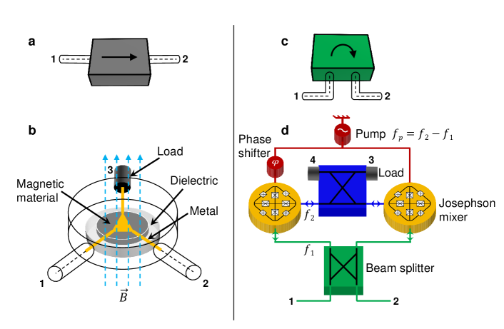
Nonreciprocity mechanism. To elucidate the basic idea behind the reciprocity-breaking mechanism of the new isolator, we qualitatively compare in Fig. 1 a state-of-the-art magnetic-based isolator, whose circuit symbol is shown in Fig. 1a and the Multi-Path Interferometric Josephson ISolator (MPIJIS) realized and measured in this work, whose circuit symbol is introduced in Fig. 1c. While the circuit of the magnetic-based isolator can be realized in several different ways Pozar , Fig. 1b exhibits a widely-used commercial realization, which captures the main common attributes of the device. In this realization, a two-port isolator is formed by terminating one port (e.g., port ) of a three-port, magnetic-based circulator with a matched load (e.g., ). As seen in Fig. 1b, the circulator consists of a microstrip metallic junction connected to the center-conductor of the equally-spaced device ports and laid down on a disk-shaped dielectric substrate, which incorporates at its center a smaller ferrite disk functioning as a resonant cavity. The circulator circuit also includes a permanent magnet, not shown in the illustration, which induces a magnetic field in the device. As a result of the magnetic bias, the lowest-order resonant mode of the ferrite cavity splits into two modes having different frequencies and nonreciprocal azimuthal phase dependence , which is set by the direction of the applied magnetic field. By engineering the amplitude of these modes via the bias field, a superposition pattern can be generated at the circulator ports, such that microwave signals at , falling between the split-resonance frequencies , propagate towards port upon entering port , whereas signals entering propagate towards the internal port and dissipate their energy at the matched load Pozar .
The MPIJIS relies, in contrast, on different physics. In Fig. 1d, we depict the main components of the device. Unlike the passive magnetic-based isolator shown in Fig. 1b, the MPIJIS consists of two active Josephson mixers coupled together in an interferometric setup formed by two beam-splitters (i.e., hybrids). The two Josephson mixers function as lossless frequency converters (without photon gain) between two signals having frequencies (green) and (blue), which are supported by the resonance modes of the mixers. By construction, signals at only excite an internal mode of the system. To enable the frequency conversion, the Josephson mixers are driven by a monochromatic microwave pump at frequency . Due to the parametric modulation of the Josephson mixers, an artificial gauge-invariant potential for microwave photons is generated, which depends on the pump phase difference AhranovBohmMixers ; AhranovBohmPhotonic ; ReconfJJCircAmpl ; NRAumentado2 . The induced potential consequently introduces a nonreciprocal phase shift for the frequency-converted signals JPCgyrator , which is exploited in combination with wave interference (enabled by the beam-splitters) for transmitting signals in one direction, i.e., from port to , and canceling signals in the opposite direction. Similar to the magnetic-based isolator (Fig. 1b), the canceled signals on the device port are directed towards the MPIJIS internal ports and where they are absorbed by the matched loads.
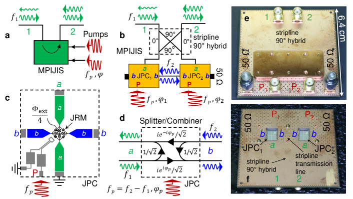
The device. The MPIJIS realized in this work is shown in Fig. 2. In Fig. 2a, we show a black-box representation of the MPIJIS. It includes two external ports and , which support propagating microwave signals at , which fall within the device bandwidth. The MPIJIS receives, for its operation, two monochromatic microwave pumps at having a certain amplitude and phase difference . The pumps are fed into the MPIJIS through auxiliary ports. In the example of Fig. 2a, the MPIJIS is operated in the forward direction, i.e., propagating signals entering port (input) are transmitted in the direction of the arrow to port (output) with almost unity transmission, whereas propagating signals entering port are significantly attenuated upon exiting port . Figure 2b exhibits a block-circuit diagram of the MPIJIS. It consists of two nominally identical Josephson parametric converters (JPCs) JPCreview ; JPCnature , which serve as lossless, nondegenerate, three-wave mixing Josephson devices as outlined in Fig. 1d. The two JPCs are embedded into an interferometric setup, which couples modes a and b via a hybrid and a short transmission line, respectively. The pump drives are fed to the JPCs via separate physical ports (denoted as P) hybridLessJPC . The circuit diagram also reveals two internal ports of the device coupled to ports b and terminated by loads. A schematic layout of the JPC is shown in Fig. 2c. It consists of two half-wavelength, microstrip resonators a and b, which intersect in the center at a Josephson ring modulator (JRM) microstripJPC . The JRM consists of four outer-loop Josephson junctions arranged in a Wheatstone bridge configuration. The four internal Josephson junctions inductively shunt the JRM and enable the resonance frequencies of resonators a and b to be tuned as a function of the applied external magnetic flux threading the JRM Roch . When , where is the flux quantum, the JRM acts as a dispersive nonlinear medium mixing three orthogonal modes with a leading nonlinear term in the system Hamiltonian of the form JPCreview . Here, is a flux-dependent coupling strength, a and b are the annihilation operators for the differential modes a and b, while c is the annihilation operator for the mode c common to both resonators. Each resonator is capacitively coupled via equal gap capacitors to two feedlines, which carry incoming and outgoing signals. The photon decay rates MHz of resonators a and b are primarily determined by the impedance mismatch created by the gap capacitors between the feedlines and resonators. In the MPIJIS configuration shown in Fig. 2b, resonator a is single ended (i.e., one feedline is shorted to ground) and the pump drive is directly injected to the JRM through a separate on-chip feedline as illustrated in Fig. 2c hybridLessJPC . When the JPC is operated as a frequency converter between modes a and b, a strong, coherent, off-resonant, common drive is applied at Conv ; QuantumNode . With such a classical drive, we obtain in the rotating wave approximation , where is a pump-amplitude-dependent coupling strength and is the pump phase. On resonance, the transmission amplitude associated with this frequency conversion process is given by , where . The transmission amplitude varies between (no conversion) and (full conversion). Since this process is unitary, the reflection and transmission amplitudes satisfy the condition . Another crucial property exhibited by is the pump-phase-dependent nonreciprocal phase shift imprinted on signals undergoing upconversion from mode a to b () versus downconversion from b to a (). This nonreciprocal phase shift is outlined in Fig. 2d, which shows a signal flow graph for the JPC operated at a special frequency-conversion working point known as the beam splitter point, where .
By coupling the two JPCs in an interferometric setup as shown in the block-circuit diagram depicted in Fig. 2b (or device photos exhibited in Figs. 2e, 2f), we convert the nonreciprocal phase shift acquired by signals transversing the two JPCs, , where is the phase gradient between the two pumps feeding the two mixers JPCgyrator , into a nonreciprocal amplitude response via constructive or destructive wave-interference between multiple paths in the device. When solving the signal flow graph for the whole device (see Fig. 5 in the Methods section), we get on resonance the following transmission parameters for ports and ,
| (1) |
and reflection parameters,
| (2) |
In the special case in which the JPCs are operated in the beam splitter point, i.e., , and the applied pump phase difference is , we obtain, by substituting in Eqs. (1), (2), total isolation of signals transmitted from port to , , and vanishing reflections off ports and , . Whereas, for signals transmitted from port to , we obtain almost unity transmission , which is equivalent to about dB loss in signal power. A detailed calculation of the scattering matrix of the MPIJIS as well as key measurement results are presented in the Methods section.
It is worth noting that the same isolator circuit presented in Fig. 2b can be used to realize a quantum-limited, phase-preserving Josephson directional amplifier, which has recently been demonstrated in Refs. JDA ; JDAQST . One main difference between the two interferometric nonreciprocal devices, relates to the mode of operation of the coupled JPCs. Here, the JPCs are operated in the frequency conversion mode with no photon gain Conv ; JPCreview , whereas in the directional amplifier application, they are operated in the nondegenerate amplification mode, where JPCreview ; JPCnature ; microstripJPC . As a direct consequence of this difference, the two nonreciprocal devices differ in two important aspects, namely, added noise and stability. While the phase-preserving directional amplifier is required by quantum mechanics to add noise equivalent to a half input photon at the signal frequency , the added noise by the isolator is mainly set by its power attenuation in the forward direction Caves ; QuantumNoiseIntro ; Conv . In the MPIJIS case, the added noise-equivalent-input-photons at the signal frequency is given by (see the Methods section). For an ideal MPIJIS, whose JPCs are joined by symmetric couplers and operated at the beam splitter point, we obtain (corresponding to on resonance). Moreover, in the directional amplifier case, the amplitude-gain of each JPC is bounded by the amplitude-attenuation of the internal mode b to ensure stability of the device in the presence of the feedback loop formed between the JPCs JDA ; JDAQST . Such a stability requirement is not applicable in the isolation case.
It is also worth noting that the dual purpose of the present device, i.e., it can be operated as a directional amplifier or isolator by changing the pump frequency, amplitude, and phase is similar to other nonreciprocal Josephson devices reported recently ReconfJJCircAmpl ; NRAumentado2 .
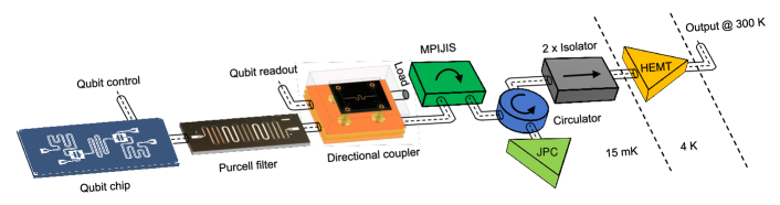
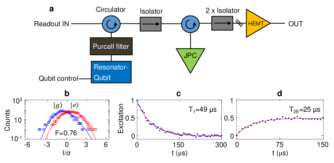
The quantum setup. To demonstrate that the MPIJIS is suitable for quantum applications, we incorporate it into a high-fidelity qubit measurement setup as shown in Fig. 3. The qubit chip used in the measurement consists of two coupled transmons, but only one transmon is measured. Each qubit has its own capacitively coupled control port, which is separate from the readout resonator port used for measurement. To enable fast readout, the qubit is dispersively coupled to a relatively large bandwidth readout resonator, in turn, coupled to a superconducting Purcell filter integrated into the same PCB as the qubit chip (for further information see the Methods section). The Purcell filter is added to preserve the qubit lifetime by suppressing spontaneous emission of qubit excitations through the fast resonator. The effective readout bandwidth of the combined resonator-Purcell system is MHz. The qubit and readout frequencies are GHz and GHz, respectively, while the qubit-state-dependent resonance frequency shift is MHz. Another important novelty of this qubit setup is the integration of a custom-made, wideband, superconducting directional coupler to couple readout pulses into and out of the readout resonator. Compared to conventional qubit setups, which utilize a circulator to measure readout resonators in reflection, utilizing a directional coupler produces two key differences: (1) the input readout signal entering the directional coupler is attenuated by about dB, which can be effectively lumped into the total attenuation of the input readout line, (2) the directional coupler is reciprocal, therefore, does not protect the qubit against noise coming from the output chain. The main advantages of using a directional coupler over a magnetic circulator are compatibility with superconducting quantum circuits and integrability with other microwave components in the measurement scheme. Further information about the directional coupler performance, fabrication, and packaging can be found in the Methods section. Following the directional coupler, which transmits the output readout signal with minimal attenuation, we incorporate the MPIJIS and a quantum-limited Josephson amplifier (i.e., JPC), separated by a cryogenic circulator. The circulator is crucial, in this case, for three reasons: (1) it separates the weak readout signal input on the JPC from the amplified reflected output signal; (2) it preserves, to a large extent, the readout fidelity of the output signal due to its relatively low insertion loss ( dB); and (3) it partially protects the qubit (by about dB) against vacuum noise amplified in reflection by the JPC.
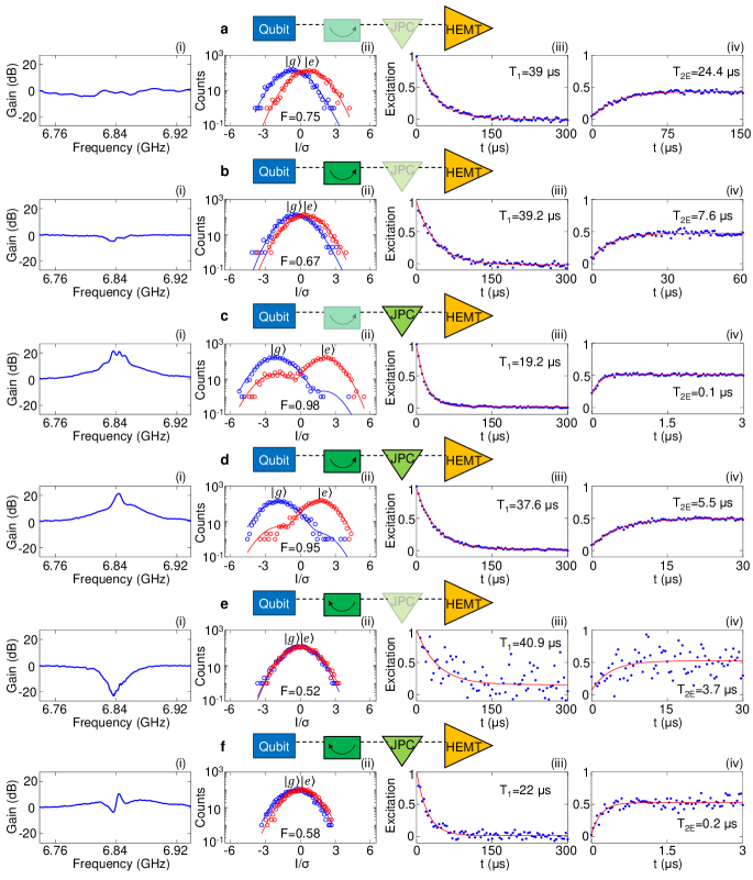
Qubit measurements. Figure 4 shows the main results of this work taken with the experimental setup of Fig. 3. Figures 4a - 4f outline the six possible measurement configurations of the MPIJIS and the JPC. The graphs in columns (i)-(iv) exhibit measurement results taken for each configuration, namely, (i) normalized gain/attenuation of the MPIJIS and JPC versus frequency, (ii) readout fidelity histograms of the output chain extracted from the in-phase quadrature (I) of the output field corresponding to the qubit being initialized in the ground () and excited () states, (iii) relaxation time , and (iv) decoherence time echo of the qubit. In configuration a, in which both the MPIJIS and JPC are off, we obtain an almost flat transmission parameter because the MPIJIS is transparent for propagating signals and the JPC is totally reflective. Using this configuration, we obtain baseline values for the readout fidelity , s and s. Very similar readout fidelities and coherence times are measured for this qubit when using the conventional high-fidelity setup instead, in which a cryogenic circulator and isolator replace the superconducting directional coupler and the MPIJIS, respectively (see Fig. 9 in the Methods section). In configuration b, we operate the MPIJIS in the forward direction while keeping the JPC off. In this case, we observe a small dip in the transmission near resonance of about dB, which can be attributed to a nonideal constructive interference taking place in the MPIJIS at this working point. The observed small dip also explains the slight decrease in the readout fidelity (ii). While we do not observe a decrease in the qubit lifetime due to the operation of the MPIJIS as seen in column (iii), we do observe a reduction, by about a factor of , in s, which we attribute to increased qubit dephasing as a result of pump-photons leaking into the readout resonator (see Fig. 11 in the Methods section). In configuration c, we turn off the MPIJIS and turn on the JPC with a gain in excess of dB at the readout frequency and a dynamical bandwidth of about MHz as shown in column (i). As expected in this quantum-limited amplification scenario, the readout fidelity is significantly enhanced . However, the enhancement in the fidelity is accompanied by a strong backaction on the qubit state, as seen in the drop of s by about a factor of and the significant reduction of s by about a factor of , compared to configuration a. This backaction is mainly caused by certain amplified in-band quantum noise, which couple to the resonator-qubit system due to insufficient isolation (i.e., only one isolation stage is present between the qubit and JPC). Next, in configuration d, we keep the JPC on and operate the MPIJIS in the forward direction. Remarkably, by turning on the active isolation, s is almost restored to the baseline-value of configuration a, while s is enhanced by a factor of compared to configuration c (i.e., without the active isolation). Moreover, the observed enhancements in the coherence times of the qubit compared to configuration c are achieved without a considerable impact on the total gain dB and readout fidelity . In the last two remaining configurations e and f, the MPIJIS is operated in the backward direction, which is attained in situ by shifting the pump phase difference of the two drives by compared to configurations b and d. In this mode of operation, the MPIJIS effectively mimics an attenuator of more than dB in the path of the readout signals as seen in column (i) of configuration e for which the JPC is off. As expected in the case of heavy attenuation of configuration e, the readout fidelity is diminished . Similar effect can also be seen in the poor signal to noise ratio of the coherence times measurements, which have a large scatter in the data points (taken with the same amount of averaging as the other cases). In general, the coherence times measured for the backward-operated isolator s, s are comparable to those of the forward-operated isolator (i.e., configuration b) within the measurement error margin. Finally, in configuration f, in which the JPC is on, the amplification of the JPC almost cancels the attenuation of the MPIJIS as seen in (i), which leads to a slight enhancement of the readout fidelity . The coherence times s, s measured for this case are quite similar to configuration c, because in both cases the isolator is not shielding the qubit against excess backaction of the preamplifier (JPC).
To quantify the backaction effect on corresponding to the different configurations, we note that because and , it follows that, in our case, the qubit coherence time is limited by dephasing, where is the dephasing time. One dominant dephasing mechanism in a qubit-resonator system operating in the dispersive coupling regime, such as ours, is photon shot noise in the resonator mode, which causes the qubit frequency to fluctuate due to the AC Stark effect AdamShotNoise ; ChadShotNoise ; CavityAtten ; ClerkShotNoise . In this case, the dephasing rate is given by , where is the average photon number in the resonator, which can be written as , where and are the average thermal and nonthermal (backaction) photon numbers, respectively. Using these relations, we can evaluate and , summarized in Table 1, for the different configurations a-f exhibited in Fig. 4. We also extract using configuration a, for which the MPIJIS and JPC are off (no backaction is present). As expected, the largest values for and are obtained for configurations c and f in which the JPC is on while the MPIJIS is off or operated in the backward direction (i.e., in a nonprotective mode). Conversely, a much smaller photon number by about two orders of magnitude is observed when the MPIJIS is operated in the protective forward direction.
| Config. | MPIJIS | JPC | (s) | (s) | (s) | |
|---|---|---|---|---|---|---|
| a | off | off | 39 | 24.2 | 35.1 | 0 |
| b | F | off | 39.2 | 7.6 | 8.4 | 0.01 |
| c | off | on | 19.2 | 0.1 | 0.1 | 1.29 |
| d | F | on | 37.6 | 5.5 | 5.9 | 0.02 |
| e | B | off | 40.9 | 3.7 | 3.9 | 0.03 |
| f | B | on | 22 | 0.2 | 0.2 | 0.64 |
Discussion
Based on the results of Fig. 4 and Fig. 7 (in the Methods section), there are several areas in which the performance of this proof-of-principle MPIJIS can be further improved: (1) isolator-backaction, which is implied by the observed reduction of when the isolator is on (Fig. 4b) versus off (Fig. 4a). One likely explanation for this backaction is pump-photon-leakage from the on-chip pump lines into resonators a of the JPCs as observed in the spectrum measurement of Fig. 11 (see the Methods section). Such leakage can be eliminated by redesigning the basic lowpass-filtering element, which is part of the on-chip pump lines shown in Fig. 2c, so that it blocks low-pump frequencies around GHz. The present filtering element, designed for a JPC-operation in the amplification mode hybridLessJPC , has a cutoff frequency around GHz; (2) excess-insertion-loss for on-resonance transmitted signals in the range dB, as seen in Figs. 4b (i), 7a,b, which is higher than the dB predicted for the ideal case (see device theory in the Methods section). This suggests that the constructive interference taking place in the forward direction is not optimal due to certain phase and amplitude imbalance of the PCB-hybrid JDAQST . By substituting the present unoptimized PCB-hybrid with an optimized on-chip version, we believe this figure and the reflections off the device ports (see Figs. 7c,d) can be significantly reduced; and (3) narrow-bandwidth of the MPIJIS on the order of MHz, limited by the resonator bandwidths of the JPCs JPCreview ; Conv . One method which could be employed to enhance the device bandwidth is impedance-engineering of the JPC feedlines. Applying such a technique in the case of single-port Josephson parametric amplifiers has successfully yielded bandwidths in the range GHz JPAimpedanceEng ; StrongEnvCoupling , which correspond to more than -fold enhancement compared to standard designs.
Additional enhancements of the device include, (1) reducing its footprint by integrating all components on chip and using lumped-element realization of the JPCs LumpedJPC and hybrids Lumpedhybrids , (2) unifying the two external ports of the pumps, as shown in Figs. 2e,f. This could be achieved by injecting a single-pump drive into the MPIJIS through an on-chip hybrid whose two output ports connect to the two-stage pump lines as proposed in Ref. JPCgyrator .
In conclusion, we have introduced and realized a new isolator device, which does not rely on magnetic materials or strong magnetic fields and is fully compatible with superconducting quantum circuits. The new isolator is comprised of two coupled, nondegenerate, three-wave Josephson mixers embedded in an interferometric scheme. The nonreciprocal response of the device is controlled by the phase gradient of the same-frequency microwave drives feeding the two Josephson mixers. Such a microwave-signal control could enable fast switching of the isolation direction on the fly with a time scale on the order of ns, which is mainly limited by the inverse dynamical bandwidth of the device. The realized isolator exhibits isolation in excess of dB, a dynamical bandwidth of MHz, insertion loss of about dB in the forward direction, signal-power reflections off its input and output ports below dB, and a maximum input power of dBm. Furthermore, we have validated the applicability of this isolation scheme for quantum measurements by incorporating it into a superconducting qubit measurement setup, which includes a transmon coupled to a fast cavity, Purcell-filter, custom-made, broadband, superconducting directional coupler, and a quantum-limited, Josephson parametric amplifier. Using this novel setup, we have demonstrated fast, single-shot, high-fidelity, QND measurements of the quantum state while providing active protection of the qubit against amplified noise originated by the Josephson parametric amplifier. Owing to its numerous desired properties, an optimized version of this Josephson isolator may play a pivotal role in scalable quantum architectures.
Methods
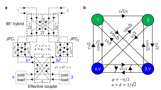
MPIJIS theory. To calculate the scattering parameters of the MPIJIS and demonstrate its isolation operation, we use the effective signal-flow graph exhibited in Fig. 5a. The graph includes signal-flow graphs for the two coupled JPCs operated in frequency-conversion mode. On-resonance signals at or input on port a (e.g., or ) or b (e.g., b1 or b2) are reflected off by a reflection-parameter and transmitted with frequency-conversion by a transmission-parameter , where and are determined by the pump drive amplitude and satisfy the energy conservation condition . In this calculation, we assume that the two JPCs are balanced, i.e., their reflection and transmission parameters are equal. It is worth noting that although we consider here the on-resonance case, it is straightforward to generalize the device response for signals that lie within the JPC dynamical bandwidth as we show below. The nonreciprocal phases and acquired by the frequency-converted transmitted signals between ports a and b, as indicated in the graph, correspond to the phases of the pump drives at frequency feeding and , respectively. Figure 5a also includes flow-graphs for two couplers coupling the a and b ports of the JPCs; one represents the hybrid, which couples between the a ports of the JPCs, while the other is a fictitious one coupling the b ports. The main role of the latter coupler is to model the amplitude attenuation present on the b port , due to signal absorption in the cold loads and the insertion loss of the normal-metal transmission line coupling the two stages. Because of the structural symmetry of our device, we consider a symmetric coupler with real coefficients and , which satisfy the condition . For an ideal symmetric coupler (i.e., hybrid), Pozar .
In the stiff pump approximation, the JPC reflection and transmission parameter amplitudes can be written as JPCreview
| (5) |
where is a dimensionless pump amplitude. The lower bound corresponds to the case of no applied pump in which the JPC is off and acts as a perfect mirror, whereas the upper bound corresponds to the case of full frequency conversion mode between ports a and b. By inspection Pozar , the scattering matrix of the inner device defined by the ports , i.e., excluding the first hybrid, can be written in the form JDA
| (10) | ||||
| (15) |
where . As we show below, it is this phase difference between the modulation phases of the two pumps feeding the two parametric active devices (i.e., the JPCs), which induces the nonreciprocal response of the MPIJIS NoiselessCirc ; AhranovBohmPhotonic ; AhranovBohmMixers ; JPCgyrator . The common coefficient that appears in the scattering parameters of Eq. (15) represents the sum over all possible reflections that the internal signals can experience in the self-loop formed between the two b ports of the device. Unlike the directional amplification case JDA ; JDAQST , where the reflection-gain amplitude needs to be bounded to ensure stability, in the case of frequency conversion, with no photon gain, the scattering parameters of Eq. (15) are stable for all values of . In this simplified model, we assume that the phase acquired by signals at frequency , propagating along the short transmission line between the two JPCs, is in each direction, where is an integer. In our device, the electrical length of the short transmission line is designed to give a phase of about at .
It is straightforward to verify that the scattering matrix of Eq. (15) is unitary (energy preserving). For example, it satisfies the condition
| (16) |
Next, we derive the scattering matrix for the whole device, defined by ports , , , , which take into account the signal flow through the hybrid,
| (21) |
whose matrix elements are given by,
| (22) |
| (23) |
| (24) |
| (25) |
| (28) |
| (31) |
| (34) |
Note that is unitary because is unitary and the hybrid is a unitary device. One prominent property seen from Eqs. (22)-(34), is the interferometric nature of the device, manifested in its scattering parameters, which represent the sum over all possible paths that the waves can propagate in it.
By substituting the scattering parameters of the inner device listed in Eq. (15) into Eqs. (22)-(34), and by writing the resulting expressions in terms of the parameter , we obtain the scattering parameters of the MPIJIS in an explicit form
| (35) |
| (36) |
| (37) |
| (38) |
| (39) |
| (40) |
| (41) |
| (42) |
| (43) |
| (44) |
| (45) |
| (46) |
| (47) |
where . In what follows, we examine a few special cases of interest and outline a few important properties of the device.
Without applied pump, i.e., , the MPIJIS scattering matrix reduces into
| (48) |
This result shows that when the device is off, the MPIJIS is transparent for propagating signals and effectively behaves as a lossless transmission line with an added reciprocal phase shift of for transmitted signals within the bandwidth of the hybrid. In the special case, where the MPIJIS is on and the phase difference between the pumps is , the scattering matrix can be written in the form
| (49) |
where , , and
| (50) | ||||
| (51) |
In the derivation of Eq. (49), we assume, without loss of generality, that .
When , , and the JPCs are biased at the beam splitter working point, the MPIJIS scattering matrix becomes
| (52) |
A graphical representation of the scattering parameters of Eq. (52) is displayed in Fig. 5b. This result shows that when the MPIJIS is operated at this working point, it functions as an isolator with vanishing reflections , almost unity transmission in the forward direction (which corresponds to an insertion loss of about dB in the signal power), and total isolation . Furthermore, it shows that the cold loads on ports and play a similar role to internal ports of standard magnetic isolators. They dissipate the energy of back-propagating signals and emit noise (e.g., vacuum noise) towards the input .
Another interesting case occurs when and . In this case, we get . This result shows that is not a fundamental upper bound on . In fact, for a highly uneven effective coupler with , and JPCs operated with little conversion , , we obtain .
To generalize the on-resonance-derived scattering parameters listed in Eqs. (35)-(47) for signals within the device bandwidth, we substitute JPCreview
| (53) |
where are the bare response functions of modes a and b (whose inverses depend linearly on and ):
| (54) |
Since the applied pump frequency satisfies the relations , of Eq. (54) can be rewritten as . Obviously, this generalization holds under the assumption that the bandwidth of the hybrid is much larger than the dynamical bandwidths of the JPCs, which is generally the case because transmission-line-based hybrids exhibit bandwidths of a few hundreds of megahertz CPWhybrids .
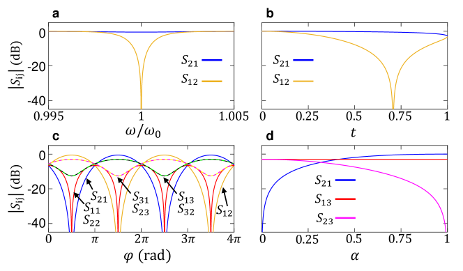
In Fig. 6, we present several key theoretical results of the MPIJIS. Figure 6a shows the transmission parameters magnitude (blue) and (orange) of the MPIJIS, operated in the forward direction, as a function of normalized frequency, where . As expected, exhibits a large dip in vicinity of the resonance while remains very close to unity. Figure 6b displays and of a forward-operated MPIJIS on resonance as a function of the JPC transmission parameter t. In Fig. 6c, we show the dependence of a rather comprehensive set of the scattering parameters on the pump phase difference , namely, (red), (blue), (orange), (dashed yellow), (dashed magenta), (dashed black), and (dashed green). Note that some of the absent scattering parameters are equal in magnitude to ones that are present, i.e., , , , , . Similar to the calculation of Fig. 6a,b the different scattering parameters in Fig. 6c are calculated using Eqs. (35), (36), (37), (40), (42), (44), (45) for the case of a symmetrical effective coupler. Also, in Figs. 6a,c, the JPCs are operated at the beam splitter point. As expected for , where is an integer, (forward transmission) assumes a maximum, while (reflection), (backward transmission) assume a minimum. Similarly, (transmission from the load to the input) and (transmission from the output to the load) assume a maximum, while (transmission from the input to the load) and (transmission from the load to the output) assume a minimum. The responses are completely reversed for . Finally, Fig. 6d displays a representative set of the scattering parameters of the MPIJIS on resonance versus the transmission amplitude between modes b of the JPCs, i.e., . In this calculation, the MPIJIS is operated in the forward direction and the transmission parameter of the JPCs is adjusted for each chosen () to yield a fixed attenuation of dB in the backward direction (not shown). As seen in the figure, asymptotically approaches in the limit . Moreover, while (transmission from the load to the input), represented by the red line, remains close to dB, (transmission from the load to the output), represented by the magenta line, approaches in the limit .
Added noise. To calculate the added noise by the MPIJIS operated in the forward direction, we compare the signal-to-noise ratio at the output to the signal-to-noise ratio at the input , where and represent the number of signal and noise-equivalent photons per mode per unit time per unit bandwidth at port i, respectively JPCreview . Using the full scattering matrix of the MPIJIS (Eq. (21)), we write , , where the last equality holds because the scattering matrix is unitary and . We also assume here that the dominant noise entering the system is vacuum noise. Using these relations, we obtain for the noise factor . Alternatively, can be expressed in terms of the number of noise-equivalent photons added by the MPIJIS to the input , where and . In this representation, . Solving for , gives , where we substituted the vacuum-noise contribution . Based on this result, we estimate the added noise by the MPIJIS in the qubit measurement of Fig. 4b to be , obtained at (corresponding to about dB dip on resonance observed in Fig. 4b (i)).
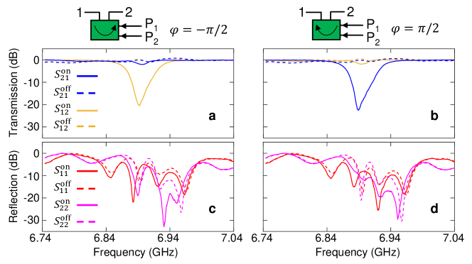
Characterization measurements of the MPIJIS. In Figure 7, we exhibit scattering parameters measurement of the MPIJIS versus frequency taken while operated in the forward direction (Figs. 7a, 7c) and the backward direction (Figs. 7b, 7d). In this measurement, taken in a separate cooldown, the MPIJIS is characterized directly without the qubit setup. The solid (dashed) curves represent measurements taken with the MPIJIS on (off). The blue, orange, red, and magenta curves represent , , , and , respectively. When the MPIJIS is off, both transmission parameters are close to unity ( dB) and the reflection parameters are suppressed (below dB), which is consistent with the MPIJIS being transparent for transmitted signals between ports and in the off state. When the MPIJIS is operated in the forward direction (Fig. 7a), remains relatively close to unity dB, while exhibits a dip of dB on resonance and a dynamical bandwidth of MHz. When the MPIJIS is operated in the backward direction, the roles played by the transmission parameters and are reversed as seen in Fig. 7b. Moreover, the reflection parameters , and are suppressed further on resonance, as expected, when the MPIJIS is on as seen in Figs. 7c and 7d.
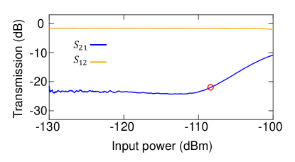
Furthermore, we measure the maximum input power which the MPIJIS can handle on resonance at a given isolation (e.g., dB), above which it saturates. The measurement result taken for the MPIJIS operated in the backward direction (same working point as Fig. 7b) is shown in Fig. 8. The plot depicts the transmission parameters (blue) and (orange) as a function of input power. As seen in the figure, is almost flat around dB up to dBm, whereas is almost flat around dB in the range between to dBm but it gradually degrades beyond dBm. One figure of merit which we apply here to quantify the saturation power of the isolator is the 1 dB compression point (denoted as ), which is commonly used to characterize amplifiers. In the amplifier case, the dB compression point usually corresponds to the input power for which the low-input-power-gain of the amplifier degrades by dB. Analogously, the dB compression point in our Josephson isolator case corresponds to the input power for which the isolation degrades by dB (denoted as ). In our device, we find dBm, which is indicated by a red circle in Fig. 8. It is worth noting that this figure is significantly larger than of microstip JPCs, when operated in the amplification mode, which is on the order of dBm JPCreview ; hybridLessJPC . This is because in the isolator case the JPCs are operated in the frequency conversion mode (without photon gain) Conv .
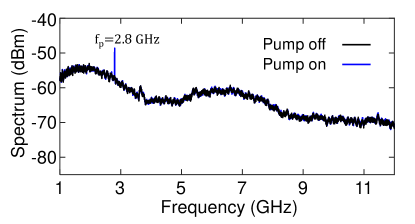
Finally, we present in Fig. 11 a broadband spectrum measured at the output of one of the MPIJIS ports. The black and blue curves are data taken using a spectrum analyzer while the MPIJIS is in the off and on states, respectively. In the on state, the MPIJIS is operated at the same working point as in Fig. 7b. As seen in the figure, the MPIJIS does not generate any spurious harmonics or noise when it is on, however, it does allow some pump power injected through the pump ports to leak out through the device ports and as indicated by the peak observed at GHz. This observation could potentially explain the slightly increased dephasing experienced by the qubit when the MPIJIS is on (Fig. 4b) versus off (Fig. 4a).
Qubit measurement parameters. The frequencies of the pumps applied to the JPC (amplifier) and MPIJIS, in the measurements of Fig. 4, are GHz and GHz, respectively. All qubit data exhibited in Fig. 4 is taken with a readout pulse duration of ns, integration time of ns, and an average photon number in the readout resonator of . The qubit data is averaged over iterations. Using the expression , we extract a qubit-state-dependent phase shift of the readout signal of . Furthermore, by substituting the histogram peak location for configuration c in Fig. 4 (in which the JPC is on) in the relation QubitJPC , we get an approximate value for the measurement efficiency of our readout chain .
Comparison to conventional high-fidelity qubit setup. In Fig. 9a we exhibit a block-circuit diagram of a conventional rapid, high-fidelity qubit readout setup, which employs magnetic-based circulators and isolators. In Fig. 9b-d we exhibit qubit measurements corresponding to qubit readout fidelity, , and , respectively, taken in a separate cooldown with the conventional setup displayed in Fig. 9a. All three measurements shown in Figs. 9b-d are taken with the JPC turned off using the same qubit-resonator-Purcell filter system and measurement parameters of Fig. 4. As seen in Figs. 9b-d, the measured readout fidelity , qubit lifetime s, and coherence time s are comparable with those measured for configuration a of Fig. 4, which uses the superconducting directional coupler and MPIJIS instead of the qubit-circulator and intermediate isolator shown in Fig. 9a. Note that although s measured with the conventional setup of Fig. 9a is slightly higher than s measured with the new setup of Fig. 3, they fall within the variation range observed for different cooldowns. It is worth noting that turning on the JPC in this conventional setup, which has three isolating stages between the JPC and the qubit-resonator, does not degrade or shown in Figs. 9c,d. It only enhances the measurement fidelity shown in Fig. 9b to about .
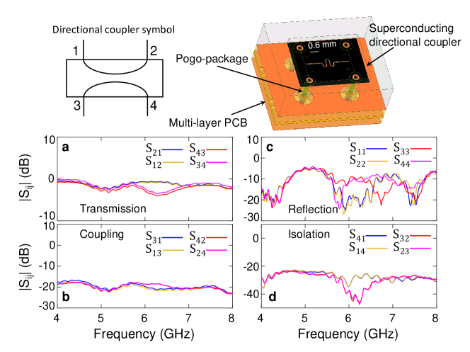
Scattering parameters of the directional coupler. The superconducting, on-chip directional coupler is realized using coupled coplanar waveguides. The characterization results of the on-chip, wideband, superconducting directional coupler are shown in Fig. 10. A circuit symbol of the directional coupler is shown in the upper-left corner of the figure, which defines the four ports of the device. The characterization measurement is done in a separate cooldown without the qubit setup, where each port of the directional couple is connected to a three-port, cryogenic circulator with its own input and output lines. A schematic image of the directional coupler chip mounted into a -matched pogo-package is shown in the upper-right corner. As seen in the image the pogos (pins) inside the package connect the four ports of the directional coupler to designated copper traces in a multi-layer PCB. The four copper traces, carrying incoming and outgoing signals, connect to surface-mount SMA connectors at the periphery of the PCB (not shown), which in our case define the directional coupler ports. In Figs. 10a-d, we exhibit calibrated measurements of the scattering parameters of the directional coupler in the GHz frequency range (limited by the bandwidth of cryogenic, three-port circulators employed in the measurement). Figure 10a exhibits the measured magnitude of the transmission parameters (blue), (orange), (magenta), (red). The data shows that the transmission through the device is close to dB in a wide bandwidth except for a narrow window around GHz, where the transmission between ports and is around dB. It is worth noting that this measurement includes the insertion loss of the multi-layer PCB, whose dielectric material is FR4 (). Figure 10b displays the measured coupling parameters (blue), (orange), (magenta), (red). The data shows that the coupling of the device is approximately flat across the bandwidth with an average value of about dB. Figure 10c plots the measured reflection parameters (blue), (orange), (magenta), (red). The data shows that the reflection off the device ports varies across the measurement bandwidth in the dB to dB range. Finally, Fig. 10d depicts the isolation parameters of the device (blue), (orange), (magenta), (red). As seen in the figure, the isolation varies between to dB in the measurement bandwidth but averages around dB.
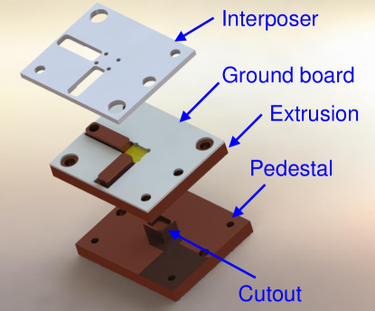
Directional coupler package. To preserve the wideband characteristics of the designed superconducting directional coupler when coupling its pads to PCB transmission lines, we utilize a pogo-package technology detailed in Ref. QST_Bronn2018 , which provides good vertical impedance-matched transitions compared to traditional wirebond technology. A blow-up of the pogo-package used is shown in Fig. 12. It consists of, from bottom to top, a pedestal, an extrusion, a ground board, and an interposer. A cutout is included in the pedestal to push any chip modes to high frequency, and the chip is aligned to the two bosses on the extrusion. The ground board is made to press down on the edges for thermalization and has plating on the inside surfaces of the cutout to avoid exposed dielectric. The tolerances are adjusted so the chip protrudes slightly above the surface of the extrusion to establish positive contact with the ground board. Wirebonds are then added from the ground board to the chip ground plane and across the traces to suppress parasitic modes. The interposer is then clamped on top and spring-loaded pins with dielectrics are used for electrical connections, as described in QST_Bronn2018 .
The Purcell filter. The Purcell filter is realized using five sections of stepped impedance coplanar waveguide (CPW) transmission lines Bronn2015b . The CPW sections have alternating characteristic impedances and lengths, i.e., of length mm, and of length mm. The Purcell filter starts and ends with a low-impedance section. The device functions as a bandpass filter for readout frequencies spanning about GHz of bandwidth around GHz. Moreover, it suppresses signals in the frequency range - GHz. More specifically, it yields an attenuation of about dB near the qubit frequency ( GHz) Bronn2015b . The Purcell filter is back-mounted into the same PCB as the qubit-resonator chip using a copper bottom cover. The qubit-resonator chip and the Purcell filter are coupled through a mm long 50 stripline transmission line within the PCB.
Fabrication process. The qubit-resonator circuit is fabricated on high-resistivity silicon by mixed optical and e-beam lithography. Large features of the superconducting quantum circuit are transferred into a thin film of niobium by optical lithography and reactive ion etch. Subsequently, the Al-Al2O3-Al Josephson junctions are defined by electron beam lithography and deposited by shadow mask evaporation in a Dolan-bridge process.
The directional coupler chip is fabricated with a single-layer optical lithography process using sputter-deposited Nb metal on a -inch, high-resistivity, float zone silicon substrate. Native oxide is removed from the substrate in situ with an Ar plasma immediately prior to deposition. The photoresist mask is then patterned on the surface of the Nb and the coplanar gaps are etched with SF6 plasma using laser-reflection endpoint detection. The photoresist mask is stripped in hot solvents. Finally, a protective coat of resist is applied before the wafer is diced into dies.
The Purcell filter is implemented using a SF6 subtractive dry etch of 200 nm thick niobium sputtered on a mm2 sapphire substrate.
Acknowledgments B.A. highly appreciates J. Rozen’s help in wiring the dilution fridge. Work pertaining to the development of the Purcell filter was supported by IARPA under contract W911NF-10-1-0324, and to the development of the pogo-pin packaging by IARPA under contract W911NF-16-1-0114-FE. Contribution of the U.S. Government, not subject to copyright.
Author Contributions B.A. designed the isolator device, performed the experiment, and analyzed the data. N.B. designed the Purcell filter and the PCBs, O.J. designed the device package, coils and mounting brackets, S.O. designed and simulated the directional coupler, A.D.C. assembled the qubit measurement setup, M.B., V.P.A., R.E.L. fabricated the devices, X.W. performed preliminary characterization of the directional couplers, D.P.P. designed and provided the package for the directional coupler, J.M.C. supervised the project. B.A. wrote the paper with input and contributions from the other authors.
References
- (1) Devoret, M. H. and Schoelkopf, R. J. Superconducting Circuits for Quantum Information: An Outlook. Science 339, 1169 (2013).
- (2) Vijay, R., Slichter, D. H. and Siddiqi, I. Observation of Quantum Jumps in a Superconducting Artificial Atom Phys. Rev. Lett. 106, 110502 (2011).
- (3) Hatridge, M., Shankar, S., Mirrahimi, M., Schackert, F., Geerlings, K., Brecht, T., Sliwa, K. M., Abdo, B., Frunzio, L., Girvin, S. M., Schoelkopf, R. J., Devoret, M. H. Quantum Back-Action of an Individual Variable-Strength Measurement. Science 339, 178 (2013).
- (4) Campagne-Ibarcq, P., Flurin, E., Roch, N., Darson, D., Morfin, P, Mirrahimi, M., Devoret, M. H., Mallet, F. and Huard, B. Persistent Control of a Superconducting Qubit by Stroboscopic Measurement Feedback. Phys. Rev. X 3, 021008 (2013).
- (5) Murch, K. W., Weber, S. J., Macklin, C. and Siddiqi, I. Observing single quantum trajectories of a superconducting quantum bit. Nature 502, 211 (2013).
- (6) Sun, L., Petrenko, A., Leghtas, Z., Vlastakis, B., Kirchmair, G., Sliwa, K. M., Narla, A., Hatridge, M., Shankar, S., Blumoff, J., Frunzio, L., Mirrahimi, M., Devoret, M. H. and Schoelkopf, R. J. Tracking photon jumps with repeated quantum non-demolition parity measurements. Nature 511, 444 (2014).
- (7) Vijay, R., Macklin, C., Slichter, D. H., Weber, S. J., Murch, K. W., Naik, R., Korotkov, A. N. and Siddiqi I. Stabilizing Rabi oscillations in a superconducting qubit using quantum feedback. Nature 490, 77 (2012).
- (8) Wang, J. and Wiseman, H. M. Feedback-stabilization of an arbitrary pure state of a two-level atom. Phys. Rev. A 64, 063810 (2001)
- (9) Ofek, N., Petrenko, A., Heeres, R., Reinhold, P., Leghtas, Z., Vlastakis, B., Liu, Y., Frunzio, L., Girvin, S., Jiang, L., Mirrahimi, M., Devoret, M., Schoelkopf, R. Extending the lifetime of a quantum bit with error correction in superconducting circuits, Nature 536, 441 (2016).
- (10) D. Ristè, J. G. Leeuwen, H.-S. Ku, K. W. Lehnert, and L. DiCarlo, Phys. Rev. Lett. 109, 050507 (2012).
- (11) Ahn, C., Doherty, A. C. and Landahl, A. J. Continuous quantum error correction via quantum feedback control. Phys. Rev. A 65, 042301, (2002).
- (12) Blais, A., Gambetta, J., Wallraff, A., Schuster, D. I., Girvin, S. M., Devoret, M. H. and Schoelkopf, R. J. Quantum-information processing with circuit quantum electrodynamics. Phys. Rev. A 75, 032329 (2007).
- (13) Wallraff, A., Schuster, D. I., Blais, A., Frunzio, L., Huang, R.- S., Majer, J., Kumar, S., Girvin, S. M. and Schoelkopf, R. J. Strong coupling of a single photon to a superconducting qubit using circuit quantum electrodynamics. Nature 431, 162 (2004).
- (14) Walter, T., Kurpiers, P., Gasparinetti, S., Magnard, P., Potočnik, A., Salathé, Y., Pechal, M., Mondal, M., Oppliger, M., Eichler, C. and Wallraff, A. Rapid High-Fidelity Single-Shot Dispersive Readout of Superconducting Qubits. Phys. Rev. Applied 7, 054020 (2017).
- (15) Caves, C. M. Quantum limits on noise in linear amplifiers. Phys. Rev. D 26, 1817 (1982).
- (16) Clerk, A. A., Devoret, M. H., Girvin, S. M., Marquardt, F. and Schoelkopf, R. J. Introduction to quantum noise, measurement, and amplification. Rev. Mod. Phys. 82, 1155 (2010).
- (17) Reed, M. D., Johnson, B. R., Houck, A. A., DiCarlo, L., Chow, J. M., Schuster, D. I., Frunzio, L. and Schoelkopf, R. J. Fast reset and suppressing spontaneous emission of a superconducting qubit. Appl. Phys. Lett. 96, 203110 (2010).
- (18) Bronn, N. T., Liu, Y., Hertzberg, J. B., Córcoles, A. D., Houck, A. A., Gambetta, J. M. and Chow, J. M. Broadband filters for abatement of spontaneous emission in circuit quantum electrodynamics. Appl. Phys. Lett. 107, 172601 (2015).
- (19) Collin, R. E. Foundations for Microwave Engineering, 2nd edition, (Wiley-Interscience, Hoboken, NJ, 2014).
- (20) Pozar, D. M. Microwave Engineering, 3rd edition, (Wiley, Hoboken, NJ, 2005).
- (21) Kamal, A., Clarke, J. and Devoret, M. Noiseless non-reciprocity in a parametric active device. Nat. Phys. 7, 311 (2011).
- (22) Kamal, A., Metelmann A. Minimal Models for nonreciprocal amplification using biharmonic drives. Phys. Rev. Applied 7, 034031 (2017).
- (23) Metelmann, A. and Clerk, A. A. Nonreciprocal Photon Transmission and Amplification via Reservoir Engineering. Phys. Rev. X 5, 021025 (2015).
- (24) Macklin, C., O’Brien, K., Hover, D., Schwartz, M. E., Bolkhovsky, V., Zhang, X., Oliver, W. D. and Siddiqi I., A near–quantum-limited Josephson traveling-wave parametric amplifier. Science 350, 307 (2015).
- (25) Zorin, A. B. Josephson Traveling-Wave Parametric Amplifier with Three-Wave Mixing. Phys. Rev. Applied 6, 034006 (2016).
- (26) Vissers, M. R., Erickson, R. P., Ku, H.-S., Vale, L., Wu, X., Hilton, G. C. and Pappas, D. P. Low-noise kinetic inductance traveling-wave amplifier using three-wave mixing. Appl. Phys. Lett. 108, 012601 (2016).
- (27) Sliwa, K., Hatridge, M., Narla, A., Shankar, S., Frunzio, L., Schoelkopf, R. and Devoret, M. Reconfigurable Josephson Circulator/Directional Amplifier. Phys. Rev. X 5, 041020 (2015).
- (28) Ranzani, L. and Aumentado, J. Graph-based analysis of nonreciprocity in coupled-mode systems. New J. of Phys. 17, 023024 (2015).
- (29) Lecocq, F., Ranzani, L., Peterson, G. A., Cicak, K., Simmonds, R. W., Teufel, J. D. and Aumentado, J. Nonreciprocal Microwave Signal Processing with a Field-Programmable Josephson Amplifier. Phys. Rev. Applied 7, 024028 (2017).
- (30) Viola, G. and DiVincenzo, D. P. Hall Effect Gyrators and Circulators. Phys. Rev. X 4, 021019 (2014).
- (31) Bosco, S., Haupt, F., DiVincenzo, D. P. Self-Impedance-Matched Hall-Effect Gyrators and Circulators. Phys. Rev. Applied 7, 024030 (2017).
- (32) Mahoney, A. C., Colless, J. I., Pauka, S. J., Hornibrook, J. M., Watson, J. D., Gardner, G. C., Manfra, M. J., Doherty, A. C. and Reilly, D. J. On-Chip Microwave Quantum Hall Circulator. Phys. Rev. X 7, 011007 (2017).
- (33) Abdo, B., Bronn, N., Jinka, O., Olivadese, S., Brink, M., Chow, J. M. Multi-path interferometric Josephson directional amplifier for qubit readout. Quantum Sci. Technol. 3, 024003 (2018).
- (34) Abdo, B., Sliwa, K., Shankar, S., Hatridge, M., Frunzio, L., Schoelkopf, R. and Devoret, M. Josephson Directional Amplifier for Quantum Measurement of Superconducting Circuits. Phys. Rev. Lett. 112, 167701 (2014).
- (35) Abdo, B., Sliwa, K., Frunzio, L. and Devoret, M. H. Directional Amplification with a Josephson Circuit. Phys. Rev. X 3, 031001 (2013).
- (36) Bernier, N. R., Tóth, L. D., Koottandavida, A., Ioannou, M. A., Malz, D., Nunnenkamp, A., Feofanov, A. K. and Kippenberg, T. J. Nonreciprocal reconfigurable microwave optomechanical circuit. Nat. Commun. 8, 604 (2017).
- (37) Barzanjeh, S., Wulf, M., Peruzzo, M., Kalaee, M., Dieterle, P. B., Painter, O. and Fink, J. M. Mechanical on-chip microwave circulator. Nat. Commun. 8, 953 (2017).
- (38) Malz, D., Tóth, L. D., Bernier, N. R., Feofanov, A. K., Kippenberg, T. J. and Nunnenkamp, A. Quantum-Limited Directional Amplifiers with Optomechanics. Phys. Rev. Lett. 120, 023601 (2018).
- (39) Ranzani, L., Kotler, S., Sirois, A. J., DeFeo, M. P., Castellanos-Beltran, M., Cicak, K., Vale, L. R. and Aumentado, J. Wideband Isolation by Frequency Conversion in a Josephson-Junction Transmission Line. Phys. Rev. Applied 8, 054035 (2017).
- (40) Kamal, A., Clarke, J. and Devoret, M. H. Gain, directionality, and noise in microwave SQUID amplifiers: Input-output approach. Phys. Rev. B 86, 144510 (2012).
- (41) Hover, D., Zhu, S., Thorbeck, T., Ribeill, G. J., Sank, D., Kelly, J., Barends, R., Martinis, J. M. and McDermott, R. High fidelity qubit readout with the superconducting low-inductance undulatory galvanometer microwave amplifier. Appl. Phys. Lett. 104, 152601 (2014).
- (42) Kerckhoff, J., Lalumière, K., Chapman, B. J., Blais, A. and Lehnert, K. W. On-Chip Superconducting Microwave Circulator from Synthetic Rotation. Phys. Rev. Applied 4, 034002 (2015).
- (43) Fang, K., Yu, Z. and Fan, S. Photonic Aharonov-Bohm Effect Based on Dynamic Modulation. Phys. Rev. Lett. 108, 153901 (2012).
- (44) Fang, K., Yu, Z. and Fan, S. Experimental demonstration of a photonic Aharonov-Bohm effect at radio frequencies. Phys. Rev. B 87, 060301(R) (2013).
- (45) Abdo, B., Brink, M., Chow, J. M., Gyrator Operation Using Josephson Mixers. Phys. Rev. Applied 8, 034009 (2017).
- (46) Abdo, B., Kamal, A. and Devoret, M. H. Nondegenerate three-wave mixing with the Josephson ring modulator. Phys. Rev. B 87, 014508 (2013).
- (47) Bergeal, N., Schackert, F., Metcalfe, M., Vijay, R., Manucharyan, V., Frunzio, L., Prober, D., Schoelkopf, R., Girvin, S. and Devoret, M. Phase-preserving amplification near the quantum limit with a Josephson ring modulator. Nature 465, 64 (2010).
- (48) Abdo, B., Chavez-Garcia, J. M., Brink, M., Keefe, G. and Chow, J. M. Time-multiplexed amplification in a hybrid-less and coil-less Josephson parametric converter. Appl. Phys. Lett. 110, 082601 (2017).
- (49) Abdo, B., Schackert, F., Hatridge, M., Rigetti, C. and Devoret, M. Josephson amplifier for qubit readout. Appl. Phys. Lett. 99, 162506 (2011).
- (50) Roch, N., Flurin, E., Nguyen, F., Morfin, P., Campagne-Ibarcq, P., Devoret, M. and Huard, B. Widely Tunable, Nondegenerate Three-Wave Mixing Microwave Device Operating near the Quantum Limit. Phys. Rev. Lett. 108, 147701 (2012).
- (51) Abdo, B. , Sliwa, K., Schackert, F., Bergeal, N., Hatridge, M., Frunzio, L., Stone, A. D. and Devoret, M. Full Coherent Frequency Conversion between Two Propagating Microwave Modes. Phys. Rev. Lett. 110, 173902 (2013).
- (52) Flurin, E., Roch, N., Pillet, J. D., Mallet, F. and Huard, B. Superconducting Quantum Node for Entanglement and Storage of Microwave Radiation. Phys. Rev. Lett. 114, 090503 (2015).
- (53) Sears, A. P., Petrenko, A., Catelani, G., Sun, L., Paik, H., Kirchmair, G., Frunzio, L., Glazman, L. I., Girvin, S. M. and Schoelkopf, R. J. Photon shot noise dephasing in the strong-dispersive limit of circuit QED. Phys. Rev. B 86, 180504(R) (2012).
- (54) Rigetti, C. Gambetta, J. M., Poletto, S., Plourde, B. L. T., Chow, J. M., Córcoles, A. D., Smolin, J. A., Merkel, S. T., Rozen, J. R., Keefe, G. A., Rothwell, M. B., Ketchen, M. B. and Steffen, M. Superconducting qubit in a waveguide cavity with a coherence time approaching 0.1 ms. Phys. Rev. B 86, 100506(R) (2012).
- (55) Wang, Z., Shankar, S., Minev, Z. K., Campagne-Ibarcq, P., Narla, A. and Devoret, M. H. Cavity Attenuators for Superconducting Qubits. arxiv:1807.04849v1.
- (56) Clerk, A. A. and Utami, D. W. Using a qubit to measure photon-number statistics of a driven thermal oscillator. Phys. Rev. A 75, 042302 (2007).
- (57) Roy, T., Kundu, S., Chand, M., Vadiraj, A., Ranadive, A., Nehra, N., Patankar, M., Aumentado, J., Clerk, A. and Vijay, R. Broadband parametric amplification with impedance engineering: Beyond the gain-bandwidth product. Appl. Phys. Lett. 107, 262601 (2015).
- (58) Mutus, J., White, T., Barends, R., Chen, Y., Chen, Z., Chiaro, B., Dunsworth, A., Jeffrey, E., Kelly, J., Megrant, A., Neill, C., O’Malley, P., Roushan, P., Sank, D., Vainsencher, A., Wenner, J., Sundqvist, K., Cleland, A., Martinis, J. Strong environmental coupling in a Josephson parametric amplifier. Appl. Phys. Lett. 104, 263513 (2014).
- (59) Pillet, J.-D., Flurin, E., Mallet, F. and Huard, B. A compact design for the Josephson mixer: The lumped element circuit. Appl. Phys. Lett. 106, 222603 (2015).
- (60) Lu, L.-H., Mohammadi, S., Ponchak, G. E., Bhattacharya, P. and Katehi, L. P. B. Design and Implementation of Micromachined Lumped Quadrature () Hybrids, Microwave Symposium Digest. IEEE MTT-S International 2, 1285 (2001).
- (61) Ku, H. S., Mallet, F., Vale, L. R., Irwin, K. D., Russek, S. E., Hilton, G. C. and Lehnert, K. W. Design and Testing of Superconducting Microwave Passive Components for Quantum Information Processing. IEEE Trans. on Appl. Supercond. 21, 452 (2010).
- (62) Bronn, N. T., Adiga, P. V., Olivadese, B. S., Xian, W., Chow, J. M., Pappas, D. P. High coherence plane breaking packaging for superconducting qubits. Quantum Sci. Technol. 3, 024007 (2018).