Child-sized 3D Printed igus Humanoid Open Platform
Abstract
The use of standard platforms in the field of humanoid robotics can accelerate research, and lower the entry barrier for new research groups. While many affordable humanoid standard platforms exist in the lower size ranges of up to 60 cm, beyond this the few available standard platforms quickly become significantly more expensive, and difficult to operate and maintain. In this paper, the igus® Humanoid Open Platform is presented—a new, affordable, versatile and easily customisable standard platform for humanoid robots in the child-sized range. At 90 cm, the robot is large enough to interact with a human-scale environment in a meaningful way, and is equipped with enough torque and computing power to foster research in many possible directions. The structure of the robot is entirely 3D printed, allowing for a lightweight and appealing design. The electrical and mechanical designs of the robot are presented, and the main features of the corresponding open-source ROS software are discussed. The 3D CAD files for all of the robot parts have been released open-source in conjunction with this paper.
I Introduction
The field of humanoid robotics is enjoying increasing popularity, with many research groups from around the world having developed platforms of all sizes and levels of complexity to investigate challenges such as bipedal walking, environmental perception, object manipulation, and human-machine interaction. The nature of robots with humanlike kinematics gives them the mobility and versatility to act in everyday environments, including eventually in the home, in a similar way to their human counterparts. The effort to start humanoid robotics research on a real platform can be high however, and often large amounts of time need to be spent on design, construction, firmware and software before the platform is sufficiently functional that the real research topics can be addressed. This is a barrier of time, money, and multifaceted technical expertise that can inhibit many research groups from gaining entry into the humanoid field. The availability of standard robot platforms can significantly reduce these initial hurdles, facilitating wider dissemination of humanoid robots, and greater collaboration and code exchange between groups that share a common platform. Capable standard platforms have the ability to invigorate and accelerate academic research, as researchers can then focus chiefly on the challenges that are most interesting to them, and contribute their advances to the state of the art in their field of specialisation.
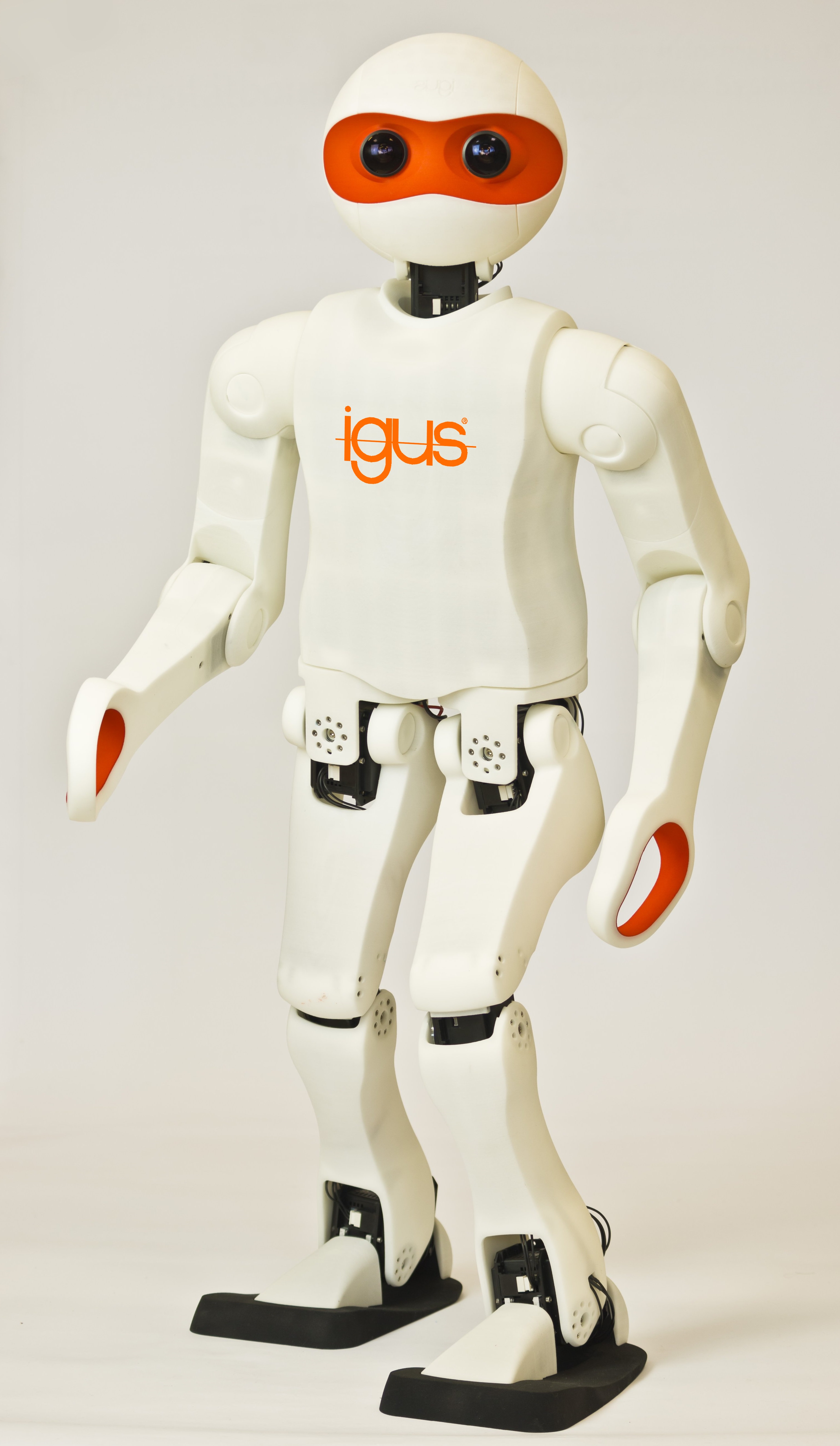
A number of standard humanoid robot platforms have been developed over the years, including notably the Aldebaran Nao and the Robotis DARwIn-OP, both of which have seen much success. The igus® Humanoid Open Platform, introduced in this paper, is shown in Fig. 1. The platform is a collaboration between researchers at the University of Bonn and igus® GmbH, a leading manufacturer of polymer bearings and energy chains. The robot has already been demonstrated at numerous industrial trade fairs, in addition to demonstrations at the most recent RoboCup and RoboCup German Open. The igus® Humanoid Open Platform seeks to close the gap between small, albeit affordable, standard humanoid platforms, and larger significantly more expensive ones such as the Honda Asimo and Boston Dynamics Atlas robots. By developing this platform, we seek to enable teams to work with an affordable robot of a size large enough to interact meaningfully with the environment. Furthermore, we designed the platform to be as open, modular, maintainable and customisable as possible, to allow the robot to be adapted to a variety of research tasks with minimal effort. The choice of using almost exclusively 3D printed plastic parts for the mechanical components of the robot forms the core of this philosophy, and also greatly simplifies the manufacture of the robots. As a result, individual parts can easily be modified, reprinted and replaced to augment the capabilities of the robot. For example, if a gripper was to be required for an application, it would be easy to design a replacement lower arm part to accommodate this. As a further example of the extensibility of the platform, the internal PC also provides the appropriate interfaces to incorporate a microphone and speakers, if this is required. In consonance with our aims of producing a platform that is entirely open, the ROS middleware [1] was chosen as the basis of the software developed for the igus® Humanoid Open Platform. This promotes the modularity, visibility, reusability, and to some degree also the platform independence, of the produced robot software in this research community-driven ecosystem. The complete hardware and software designs, the former in the form of print-ready 3D CAD files [2] and the latter with documentation [3], are available open source.
II Related Work
Over the last decade, a number of humanoid robotic platforms have been introduced that demonstrate how the use of a standard platform can accelerate research and development, by alleviating the need for teams to each ‘reinvent the wheel’ for low level tasks such as communications and walking. The most prominent example of this is the Nao robot [4], developed by Aldebaran Robotics and first released publicly in 2008. By now, many thousands of Nao robots are in use all over the world. The large dissemination was driven in part by their use as the standard humanoid platform for the RoboCup Soccer SPL competition. The Nao comes with a rich set of features, such as a variety of available gaits, a programming SDK, and well-developed human-machine interaction components. However, at tall, Naos often require special miniaturised environments, with objects on a scale that the robot can manipulate or step onto. Also, as a proprietary product, there are only very limited possibilities for own hardware repair and customisation.
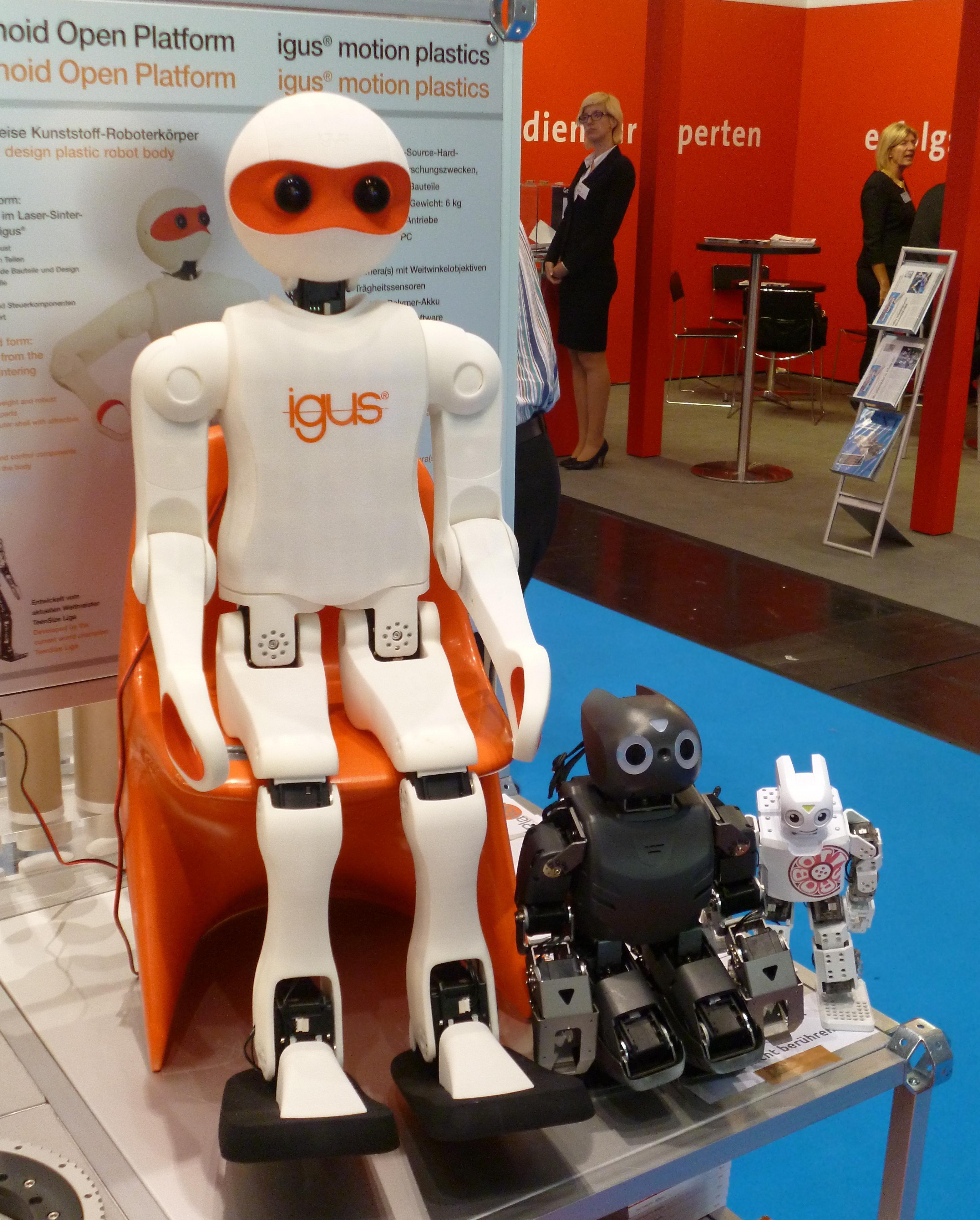
Another example of a successful standard platform is the DARwIn-OP [5], and its recent successor the ROBOTIS OP2, distributed by Robotis. Both robots are quite similar in design and architecture, and stand at tall, almost exactly half the size of the igus® Humanoid Open Platform. Fig. 2 shows a size comparison between the two robots and a Darwin-Mini, which is only tall. In contrast to the closed proprietary design of the Nao robot, the DARwIn-OP was designed as an open platform that allows users to operate, maintain and customise the robot as they desire. Nevertheless, the size of the robot has remained a limiting factor to its range of applications.
Two more recently developed platforms include the Intel Jimmy robot, and the Poppy robot from the Inria Flowers Laboratory [6]. Both of these robots are open source platforms that are for the most part 3D printed. At tall, the Jimmy robot is intended for social interactions, and comes with software based on the DARwIn-OP framework that includes for example a walking engine. The robot only uses 3D printed parts for its outer shell, but its weight is supported by an internal aluminium frame. The Poppy robot on the other hand, is more completely 3D printed, and is intended as a research platform with a compliant bio-inspired morphology. The robot is tall, has a multi-articulated trunk, and features a skeletonised design. Poppy has so far only demonstrated walking in an assisted manner, and is generally intended for non-autonomous use, with persistent cabled connections to the robot and off-board processing.
Larger standard platforms, such as the Asimo [7], HRP [8] and Atlas robots, quickly run into the limitation that they become an order of magnitude more expensive, and more difficult, or even dangerous, to operate and maintain. Such large robots also have a significantly lower robustness to falling in terms of hardware damage, and require a gantry in normal use. These factors limit the possibility of the use of such robots by most research groups.
The igus® Humanoid Open Platform bridges the gap between the existing larger and smaller standard platforms in that it is large enough to act in a human-scale environment, yet small enough to fall down and get back up, and lighter for its size than all of the other robots when compared by body mass index (BMI). The cost of the platform is about twice that of the DARwIn-OP. In 2012, work commenced on the first prototype of a child-sized humanoid platform, dubbed the NimbRo-OP [9]. The NimbRo-OP was constructed mainly out of aluminium profiles and carbon composite sheets, with only the head and a few other small parts being 3D printed. The manufacturing was completed in-house, and required the milling of parts from up to four sides, but yielded a very rigid and light-weight result. An earlier form of the ROS software was developed for the NimbRo-OP, and both the hardware and software were released open source [10]. This produced quite some interest in the platform, and although it should be stated that it was an academic as opposed to a commercial effort, several groups from around the world purchased the platform, or produced variants of their own using our hardware specifications. The igus® Humanoid Open Platform represents the next step in the evolution of the NimbRo-OP into a robust multifaceted humanoid robotics platform, and is to be seen as an open contribution to the humanoid robotics community to help more research groups enter the field.
III Robot Design Concept
| Type | Specification | Value |
| General | Height | |
| Weight | ||
| Battery | 4-cell LiPo (, ) | |
| Battery Life | – | |
| Material | Polyamide 12 (PA12) | |
| PC | Product | Gigabyte Brix GB-BXi7-5500 |
| CPU | Intel i7-5500U (4 threads) | |
| Frequency | – | |
| RAM | DDR3 | |
| Disk | SSD | |
| Network | Ethernet, Wi-Fi, Bluetooth | |
| Other | 4USB 3.0, HDMI, MiniDP | |
| CM730 | Microcontroller | STM32F103RE (Cortex M3) |
| Memory | Flash, SRAM | |
| Frequency | ||
| Other | 3Buttons, 7Status LEDs | |
| Actuators | Total | 8MX-64, 12MX-106 |
| Head | 2MX-64 | |
| Each Arm | 3MX-64 | |
| Each Leg | 6MX-106 | |
| Sensors | Encoders | |
| Gyroscope | 3-axis (L3G4200D chip) | |
| Accelerometer | 3-axis (LIS331DLH chip) | |
| Magnetometer | 3-axis (HMC5883L chip) | |
| Camera | Logitech C905 (720p) | |
| Camera Lens | Wide-angle lens with 150∘ FOV |
A summary of the main hardware specifications of the igus® Humanoid Open Platform is shown in Table I. Other than an appealing overall aesthetic appearance, for which a design bureau was engaged, the main criteria for the design were the simplicity of manufacture, assembly, maintenance and customisation. To satisfy these criteria, a modular design approach was used. This is evident, for example, in the choice of using a high performance small form factor PC with standard mounting points in a location in the torso where space requirements are flexible. As such, it is very simple to upgrade the PC in the robot. If the layout of the external PC sockets changes, the only potentially required hardware change is the replacement of the white plastic cover on the back of the robot that covers the PC. As this cover is printed in a modular fashion separately from the remainder of the torso, it is very easily replaced with a part that has holes in the correct locations for the new PC. Since the initial NimbRo-OP prototype was built, the PC has been changed twice to augment the computational power.
The modular design of the robot is also demonstrated by its ability to allow quick design iterations. Due to the 3D printed nature of the robot, parts can be modified and replaced with great freedom. For instance, in one of the first iterations of the design, it was found that one of the leg parts did not allow for an adequate range of motion in the hips. This issue was quickly resolved with the simple change of the associated dimensions in the CAD model, and the subsequent reprinting of the part.
IV Mechanical Design
While the kinematic structure of the igus® Humanoid Open Platform is very similar to that of the NimbRo-OP, its structural design was changed fundamentally. This was motivated largely by the desire for a greater overall visual and aesthetic appeal of the robot, but it also had many other benefits, such as a significant reduction in the total number of parts. The resulting robot design, shown in Fig. 1, was awarded the first RoboCup Design Award in 2015, based on criteria such as performance, simplicity and ease of use. Whereas the NimbRo-OP consisted entirely of a strongly connected array of load-bearing aluminium and carbon composite structures with no outer facade or walls, the new design consists entirely of the uniform white plastic exoskeleton that is visible externally. This facilitated a transition to cable routing internally through the limbs, as opposed to the partially external cable routing that was utilised in the NimbRo-OP. The plastic parts of the new design are 3D printed from Polyamide 12 in increments of less than using a Selective Laser Sintering (SLS) process. It is important to note that there are no extra parts behind the outer surface that help support the robot structure. The exoskeleton is simultaneously load-bearing and for outward appearance, and strongly fulfils both these functions. This allows for dramatic space and weight savings, as evidenced by the igus® Humanoid Open Platform’s very low weight. The structural integrity and resistance to deformation and buckling is ensured through modulation of the wall thickness in the areas that require it, and through strategic widespread use of ribs and other geometric strengthening features, which are printed directly as part of the exoskeleton. Essentially, through the freedoms of 3D printing, the plastic part strengths can be assigned exactly where they are needed, and not unnecessarily in other locations. This is a second reason why the weight of the new mechanical design is so low. If a weak spot is identified through practical experience, as indeed happened during walking tests, the parts can locally be strengthened in the CAD design without significantly impacting the remainder of the design.
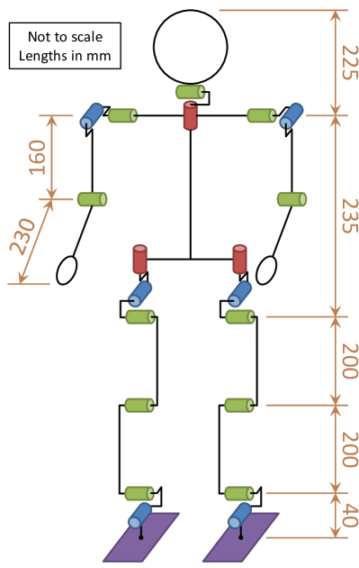
The kinematic structure of the robot is shown in Fig. 1. Starting from the trunk, the head can first yaw and then pitch, and the arms first pitch and then roll in the shoulder, before allowing pitch again in the elbow joint. There are three degrees of freedom (DOF) in each hip—first yaw, then roll and then pitch—one DOF in each knee, and two DOF in each ankle—first roll and then pitch. Position controlled Robotis Dynamixel MX-64 and MX-106 servos are used for all of the actuators, and mechanically form the sole connections between the parts, except for in the hips, where igus® axial thrust bearings provide the required dry rubbing self-lubrication.
Two noteworthy changes in the kinematics over the NimbRo-OP, are that the feet are more strongly reinforced—increasing their rigidity to elastic deformation—and that the mount point for the ankle is further back on the foot. This reduces the effect that the backlash in the ankle pitch actuator has on the stability and balance of the robot during walking, and avoids similar effects caused by bending of the feet under unbalanced loads.
V Electronics
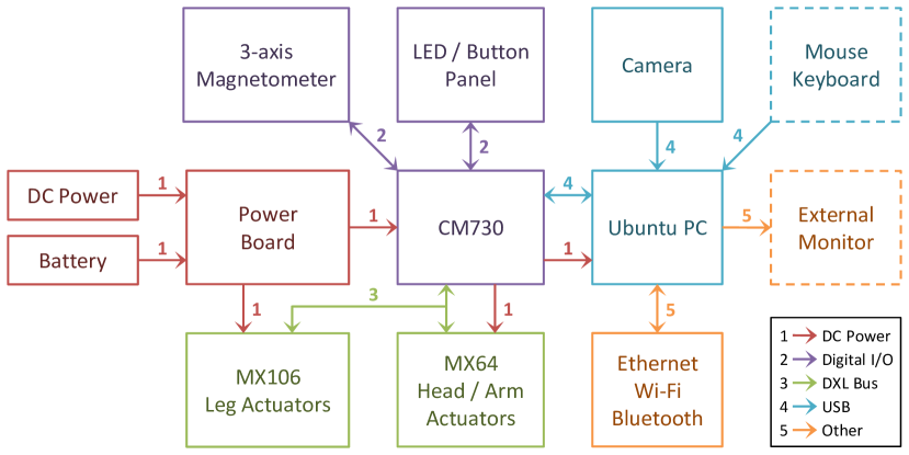
Other than for an upgrade of the PC, the electrical design of the igus® Humanoid Open Platform has remained very similar to that of the NimbRo-OP prototype, which in turn was inspired by the configuration of the DARwIn-OP robot. A block diagram of the electrical subsystem of the robot design is shown in Fig. 3. At the heart of the electrical design is the Robotis CM730 sub controller board, which contains power management features, management of a Dynamixel bus, and a Cortex M3 STM32F103RE microcontroller running at , alongside numerous other peripheral features. The CM730 is connected via USB to a PC running a full 64-bit Ubuntu operating system. All of the robot control software and processing runs on this Intel i7-5500U PC. DC power is provided to the system via a power board that incorporates a switch for the entire robot. One or both DC power and a 4-cell Lithium Polymer (LiPo) battery can be connected, and the higher voltage of the two is forwarded to supply all electronics of the robot.
The main purpose of the CM730 is to electrically interface the eight MX-64 and twelve MX-106 servos, all connected on a single Dynamixel bus. In the igus® Humanoid Open Platform design, the use of servo daisy-chaining has been kept to a minimum for stability and robustness reasons. Five separate connectors on the side of the CM730 are used to create a star topology, with daisy-chaining only being required for mechanical reasons in the elbow and ankle joints. The actuators are used in position control mode, and provide joint encoder feedback with a resolution of 4096 ticks per revolution via the Dynamixel bus.
Due to a number of factors, including reliability, performance, data latency, throughput and changed electrical connections, the standard shipped firmware of the CM730 did not satisfy the requirements of the igus® Humanoid Open Platform. As a result, the firmware of the CM730 was fundamentally redesigned and completely rewritten. Many changes and improvements were made in the process, the most notable of these being an extension of the Dynamixel protocol for communications between the CM730 and the PC. These extensions translated into significant gains in bus stability and error tolerance, as well as in time savings for bulk reads of servo data. It should be noted however, that the upgraded communications protocol is fully back-compatible with the standard Dynamixel protocol.
In addition to the actuators, the CM730 also connects to an interface panel that contains three buttons, five LEDs and two RGB LEDs. These elements are managed by the PC, and can be used to display information about the internal state of the robot, and provide control triggers. The CM730 incorporates a 3-axis gyroscope and a 3-axis accelerometer. An additional 3-axis magnetometer is connected via an I2C interface to the onboard microcontroller. The resulting 9-axis IMU is polled at high frequency and placed into registers that can be queried by the PC. A 720p Logitech C905 USB camera, located in the head of the robot and fitted with a 150∘ FOV wide-angle lens, is connected directly to the PC. Further available external connections to the PC include USB, HDMI, Mini DisplayPort, Gigabit Ethernet, IEEE 802.11b/g/n Wi-Fi, and Bluetooth 4.0. By default, the Ethernet network interface of the PC is configured system-wide to automatically switch between static and DHCP connections as required, also allowing simultaneous use of the static secondary IP address while DHCP is active.
VI Software Architecture
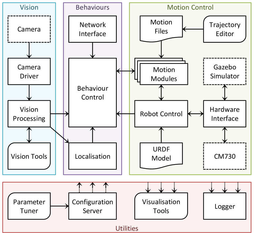
The software that has been developed for the igus® Humanoid Open Platform is a continuous evolution of the C++ ROS-based software that was written for the NimbRo-OP [10], and is available open source [3]. The overall software architecture, illustrated in Fig. 4, has not fundamentally changed since the release of the NimbRo-OP software. Many new software components have been added though, and the individual components that already existed have undergone vast changes and improvements to enhance functionality, reliability and robustness. The software was developed under the guise and target application of humanoid robot soccer [11], but with suitable adaptation of the behaviour control, vision processing and motion module sections, software for virtually any other application can be realised. This is possible because of the strongly modular way in which the software was written, greatly supported by the natural modularity of ROS. In many parts of the software framework, like for example in the choice of gait, plugin schemes are used for exactly this purpose, and individual tasks have been separated as much as possible into different nodes, often with great independence.
At the heart of the lower level control section of the igus® Humanoid Open Platform is the Robot Control ROS node, which runs a hard real-time control loop that manages sensor and actuator communications, state estimation and motion generation. A URDF (Unified Robot Description Format) model of the robot is loaded from file, and a per-launch configurable selection of motion module plugins use this information in addition to sensory perception to generate dynamic motions for the robot. A further hardware interface plugin scheme is used to manage the physical communications with the robot, or interfaces to a virtual dummy robot or a physically simulated one in the Gazebo simulator. The higher level planning and artificial intelligence is implemented in a Behaviour Control ROS node, based on the hierarchical Behaviour Control Framework [12]. Processing of the camera images is implemented in a separate vision processing ROS node, which publishes the information required by the behaviours and the localisation ROS nodes. A number of framework-wide helper nodes have also been implemented, of which the visualisation tools, configuration server and logger find the most prominent use. The configuration server is a centralised storage location and manager for software parameters, and replaces the ROS parameter server for dynamic reconfiguration of the software, and the parameter tuner GUI allows live modification of the parameters. Typically, the visualisation tools and parameter tuner are run on an external PC, but the configuration server and logger are run on the robot.
VII Dynamic Motion Generation
VII-A Compliant Actuation
In controlling the actuators of a robot, it is desirable to have a controller that can follow commanded trajectories, but at the same time remain compliant [13]. In the case of the igus® Humanoid Open Platform, inverse dynamics calculations from the RBDL library [14] are used in a feed-forward manner to predict the torques that are required in order to follow a particular joint command. These torques are then used to improve tracking performance, and allow more compliant settings to be used in the Dynamixel actuator control loops. Based on the robot state, support coefficients are estimated for each limb, and the inverse dynamics are used to provide gravity compensation based on these support coefficients via the principle of superposition. The torques required to counter the inertial effects derived from the required joint velocities and accelerations are calculated in a separate execution of the inverse dynamics. The total required torque is summated for each joint and sent to the servo control loop. The compliant servo actuation framework was found to increase battery life and reduce servo overheating and wear.
VII-B State Estimation
Estimation of the robot state is a fundamental component of essentially all dynamic motion generation algorithms that implement closed loop control. Proprioception in the ROS software is based on the joint encoder values that are returned by the servos, and managed by the convenient ROS-native tf2 library, which uses the URDF model of the robot. Estimation of the 3D orientation of the robot relative to its environment is a more difficult task however, and requires fusion of the 9-axis IMU measurements. Based in part on a novel way of representing orientations, namely the fused angles representation [15], a 3D nonlinear passive complementary filter was developed for this purpose [16]. This filter returns the full 3D estimated orientation of the robot, and is proven to be globally stable.
An immediate application of the results of the state estimation is the fall protection motion module, which disables torque in all servos if the estimated angular deviation from vertical exceeds the limit of assumed irrecoverability. This mechanism aims to protect the servos and mechanical components from damage due to the impulsive impacts associated with falling. After falling, the state estimation is used to determine whether the robot needs to get up from the front, back or side.
VII-C Keyframe Motions
There are many situations where a robot may have to execute a particular hand-tuned motion a number of times. In such situations, it is useful to be able to express and tune the motion as a set of pose keyframes that are automatically interpolated to become a complete whole body motion, which can be played back on request. This is the purpose of the motion player in the ROS software, which implements a generic nonlinear keyframe interpolator that, given the desired keyframe time intervals, is able to smoothly connect specifications of joint positions and velocities. In addition to this, the keyframe interpolator can also modulate the joint efforts and support coefficients (refer to Section VII-A) used during the motion. This allows the compliant servo actuation framework to be used meaningfully during motions with changing support conditions.
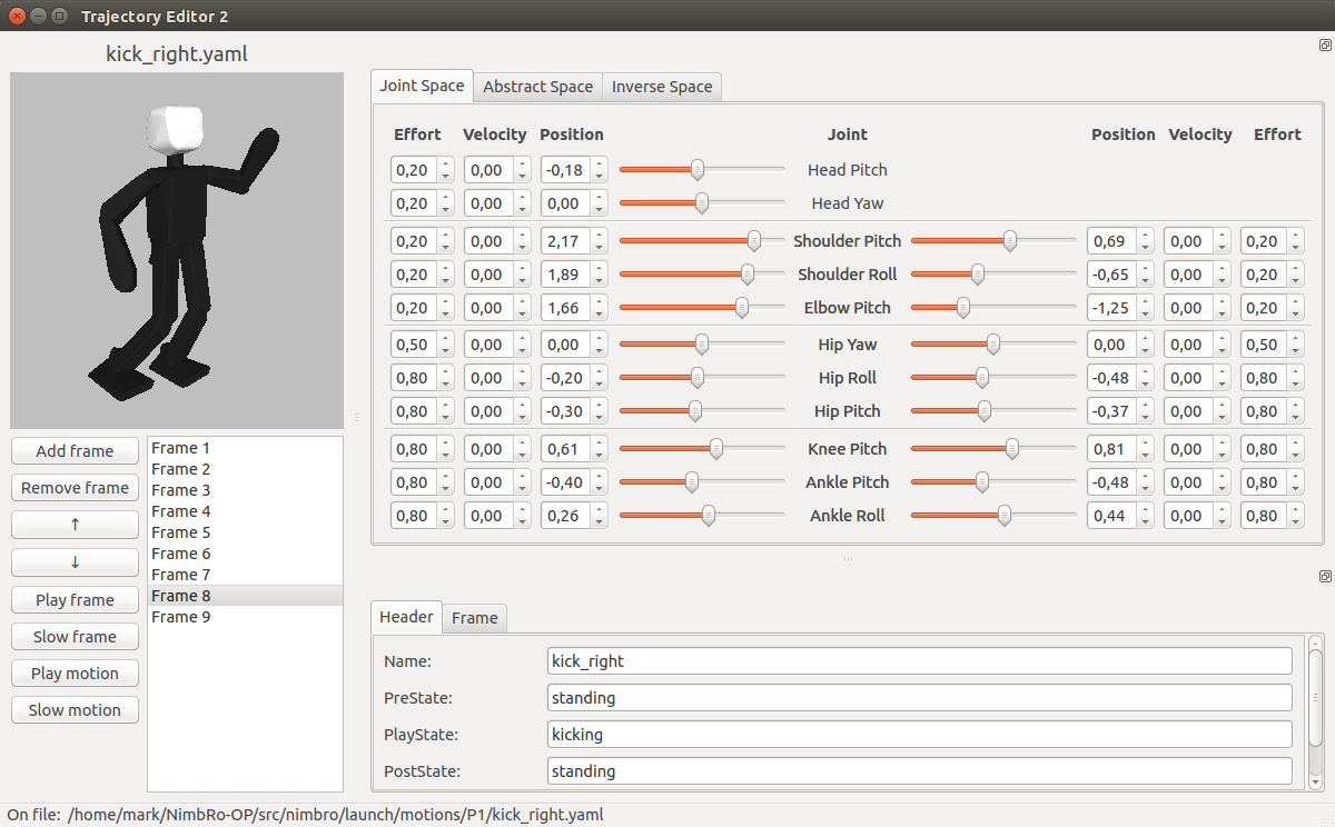
To make the keyframe motion player practicable however, a suitable tool for the editing of raw motion specification files is also required. Fig. 5 shows a screenshot of the trajectory editor that was developed for the igus® Humanoid Open Platform. With this editor, all aspects of the motion files can be edited in a user-friendly environment, and with an interactive 3D preview of the robot poses. What distinguishes this editor is that the keyframes can be edited either in:
-
•
Joint space, by direct manipulation of the joint angles,
-
•
Inverse space, by specification of the limb end effector (i.e. foot, hand) poses in terms of Cartesian coordinates and a 3D orientation, or
-
•
Abstract space, by specification of the required arm, foot and leg parameters.
The last of the three spaces, the abstract space, is a space that was developed specifically for legged robots in the context of walking and balance [17]. It abstracts the pose of the limb of a robot, nominally a leg, into specifications of the required leg extension, and rotations of the foot relative to the trunk, and , and rotations of the leg centre line relative to the trunk, following the Euler ZXY convention. The leg centre line is defined to be the line joining the centre of the hip joint and the ankle joint. Basic trigonometric conversions between joint space and abstract space exist.
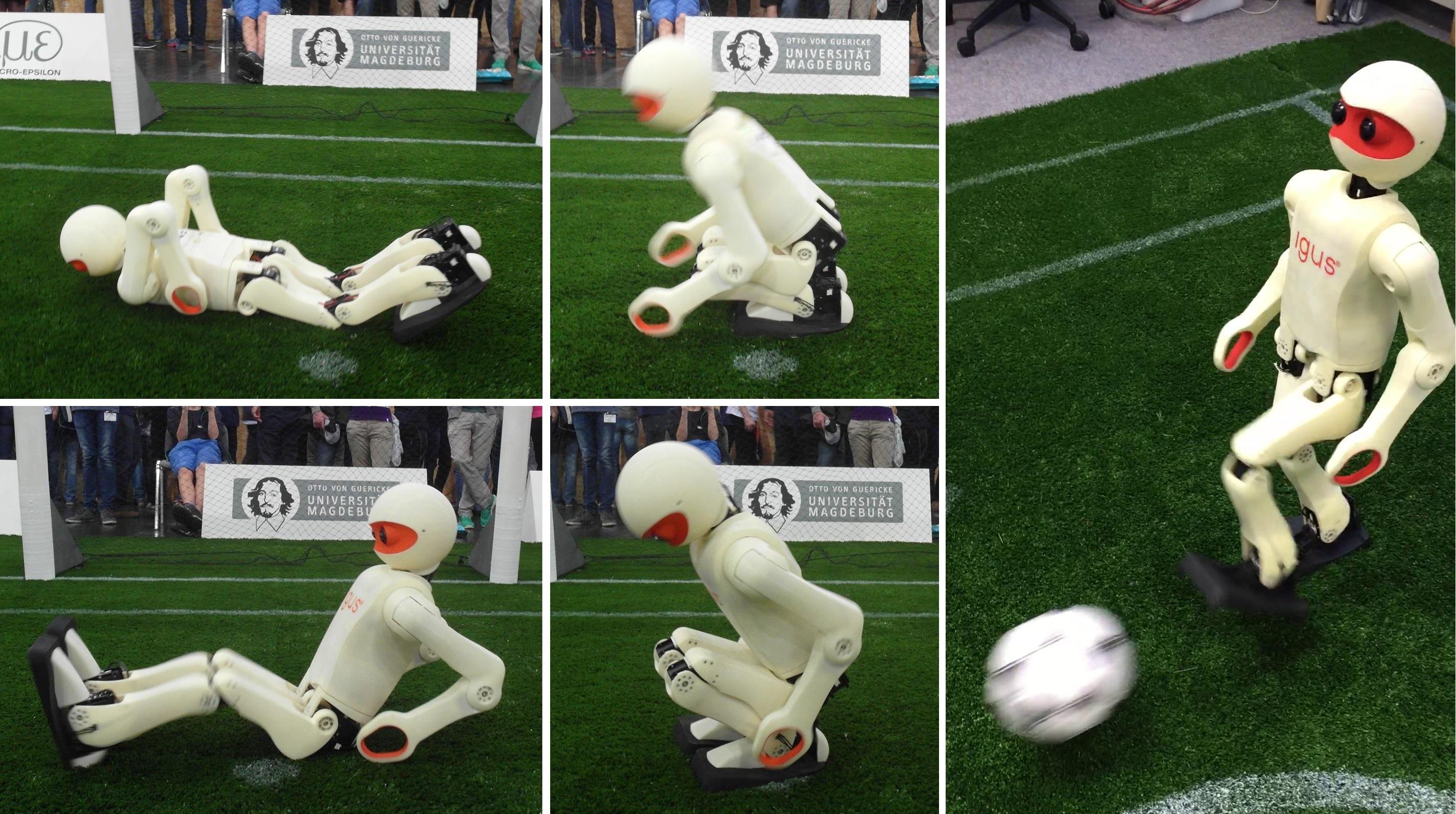
Motions that have been designed using the trajectory editor include kicking, waving, demonstration and get-up motions. The waving and demonstration motions have been used at various industrial trade fairs for publicity and interaction purposes. The kicking motions are relatively dynamic, and are able to propel a size 4 FIFA ball across blade length artificial grass, which provides a high rolling resistance. A still image of the kicking motion is shown in Fig. 6. The two main get-up motions of the igus® Humanoid Open Platform are also shown in the same figure. Four additional get-up motions handle the cases where the robot is lying on its side. With help of the support coefficients feature, the get-up motions can be efficient and controlled, and are considerably faster and more dynamic than those of most other robots of comparable size. In fact, there are extended leg flight phases during both the prone and supine get-up motions, where the only points of contact of the robot with the ground are the tips of the two arms, during which time the legs of the robot are swung underneath it. The get-up motions from the prone and supine positions take 3 and 4 seconds respectively, measured from the moment that the robot starts to fade in its torque to when the robot is supported in a balanced way on only its two feet.
VII-D Gait Generation
Motivated by the changed game environment at the RoboCup competition—the chosen application domain for our own use of the igus® Humanoid Open Platform—the gait generation has been adapted to address the new challenge of walking on artificial grass. The use of a soft, deformable and unpredictable walking surface imposes extra requirements on the walking algorithm. Removable rubber cleats have been added at the four corners underneath each foot of the robot to improve the grip on the artificial grass. This also has the effect that the ground reaction forces are concentrated over a smaller surface area, mitigating at least part of the contact variability induced by the grass.
The walking gait in the ROS software is based on an open loop central pattern generated core that is calculated from a gait phase angle that increments at a rate proportional to the desired gait frequency. This open loop gait is formulated in a combination of the abstract and inverse pose spaces (see Section VII-C), and extends the open loop gait of our previous work [18]. The main changes that have been made include:
-
•
The integration of an explicit double support phase of configurable length for greater walking stabilisation and passive damping of oscillations,
-
•
The modification of the leg extension profiles to transition more smoothly between swing and support phases,
-
•
The incorporation of a sagittal leg angle term that trims the angle relative to the ground at which the feet are lifted during stepping,
-
•
The addition of a support coefficient transitioning profile for use with the compliant servo actuation,
-
•
The use of a dynamic pose blending algorithm to enable smoother transitions to and from walking,
-
•
The adaptation of the gait command velocity-based leaning strategy to use a hip motion instead of a leg angle motion, and
-
•
The introduction of a gait command acceleration-based leaning strategy.
A number of simultaneously operating basic feedback mechanisms have been built around the open loop gait core to stabilise the walking. The feedback in each of these mechanisms derives from the fused pitch and fused roll [15] state estimates.
Virtual Slope Walking: If the robot is walking with a non-zero velocity in the sagittal direction and begins to tip either forwards or backwards, there is a possibility that due to the leg swing motion the swing foot unintentionally collides with the ground. This causes premature contact of the foot with the ground, and the robot briefly pushes its leg in a direction that undesirably promotes further tipping of the robot. Virtual slope walking adjusts the inverse kinematics height of the feet in proportion to their swing state and measured sagittal torso angle in such a way that the robot effectively lifts its feet more for foot placements if it is tipping in the direction in which it is walking.
Fused Angle Deviation Pose Feedback: During regular stable open loop walking, the torso attitude undergoes regular limit cycles in both the lateral and sagittal directions. These trajectories are modelled in terms of fused pitch and fused roll using parameterised sinusoids that are functions of the gait phase. During walking, deviations to the expected trunk attitude are used to construct proportional, integral and derivative feedback terms. The proportional feedback term is obtained by applying deadband to the output of a mean filter that takes the fused angle deviations as its input, while the integral feedback term is obtained by applying an exponentially weighted integrator to the fused angle deviations. The derivative feedback term is obtained by applying a first order differentiating weighted line of best fit filter. This inherently provides enough smoothing on the differentiated output for feedback purposes. A matrix of gains is applied to the PID feedback vector, and the resulting feedback signals are applied to a set of stabilising mechanisms, namely phased offsets to the foot angle, leg angle, hip angle, arm angle and inverse kinematics centre of mass (CoM) position. This has the effect, for example, that the front of the support foot is pushed down into the ground, and the arms are moved backwards, when the robot is tipping forwards. The integral feedback terms work on a slower time scale, and essentially learn stabilising offsets to the central pose of the gait.
Fused Angle Deviation Timing Feedback: While the fused angle pose feedback attempts to force the robot back into a regular gait limit cycle, the deviation timing feedback instead adapts the timing of the gait based on the deviation of the fused angle. It does this by adding proportional feedback from the current fused roll deviation to the rate of progression of the gait phase. Thus, if for example the robot starts to tip outwards over a support foot, the error in the fused roll causes the rate of the gait phase to slow down, effectively causing the robot to wait longer before attempting to land the next step. The opposite situation of an unbalance towards the swing foot would cause a speed up of the gait phase, causing the robot to land its next step sooner. A region of deadband ensures that small natural deviations in the fused roll do not inject timing noise into the gait.
Resulting Gait: With these feedback mechanisms in place, an omnidirectional gait was achieved on an artificial grass of blade length, with a walking speed of approximately . The cleats made a clear difference to the resulting stability of the gait, by reducing the sensitivity of the gait to the surface that the robot was walking on. On rare occasions, when the expected timing of the gait was too greatly disturbed by the grass during walking, the cleats got caught in the blades, causing further disturbances. In many cases however, even such situations were recoverable and did not necessarily lead to a fall.
VIII Vision System
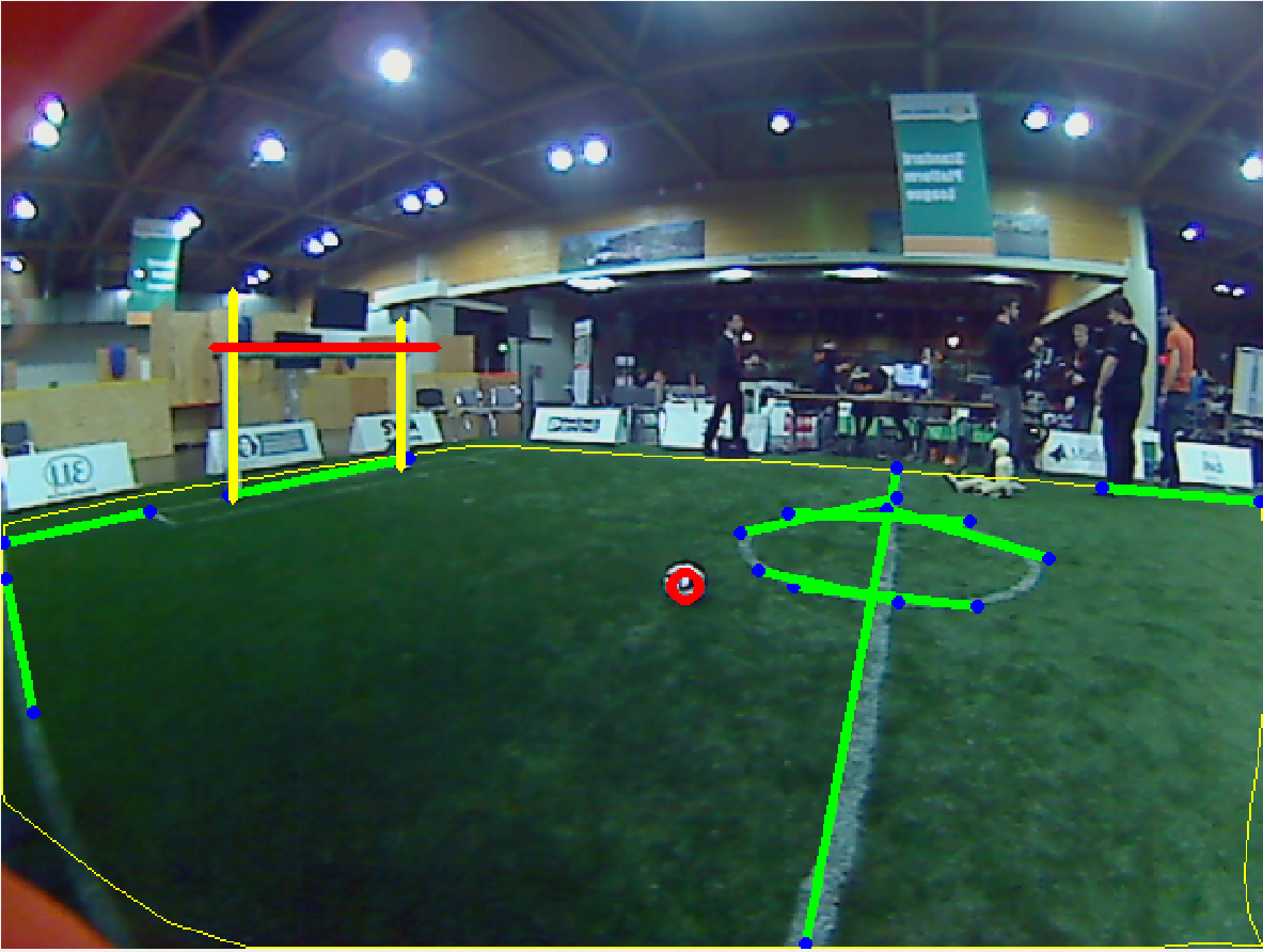
The igus® Humanoid Open Platform is nominally fitted with a single 720p Logitech C905 camera behind its right eye. A second such camera can be mounted behind the left eye however, if needed for stereo vision. The camera is fitted with a wide-angle lens, yielding a field of view of 150∘. The choice of lens was optimised from the first NimbRo-OP prototype to increase the number of usable pixels and reduce the level of distortion, all without significantly sacrificing the effective field of view. The Video4Linux2 camera driver used in the ROS software nominally retrieves camera images at in 24bpp BGR format at a resolution of . For further processing, including for example colour segmentation, the captured image is converted to the HSV colour space. In our target application of soccer, the vision processing tasks include field, ball, goal, line, centre circle and obstacle detection. A sample output of the detections in an image captured by the robot is shown in Fig. 7.
Due to the significant recent changes in the rules of the RoboCup Humanoid League—relating largely to the visual features of the soccer field, including the introduction of a mostly white ball and white goals—new detection routines with reduced dependence on colour segmentation have been developed. For ball and goal detection, a histogram of oriented gradients (HOG) descriptor is applied in the form of a cascade classifier, with use of the AdaBoost technique. Sets of positive and negative samples are gathered directly from the robot camera, and used to train the classifier. Training with 20 stages, 400 positive and 700 negative samples takes about 10 hours, and the resulting classifier has a success rate above 80% on a walking robot, with very few false detections. As the HOG feature extraction is computationally expensive if applied to the whole image, some preprocessing steps are included to reject parts of the scene that do not contain objects of interest.
Due to the new artificial grass field in the humanoid league, line detection based on colour segmentation is no longer easily possible, mainly because the painted lines are no longer a clear white. Instead, an edge detector is used on the image brightness, followed by a probabilistic Hough Transform for line segment detection. The resulting line segments are filtered and merged based on their relative detected position in world coordinates. Shorter line segments are used to try to extract the field circle, and longer ones are used to update the localisation.
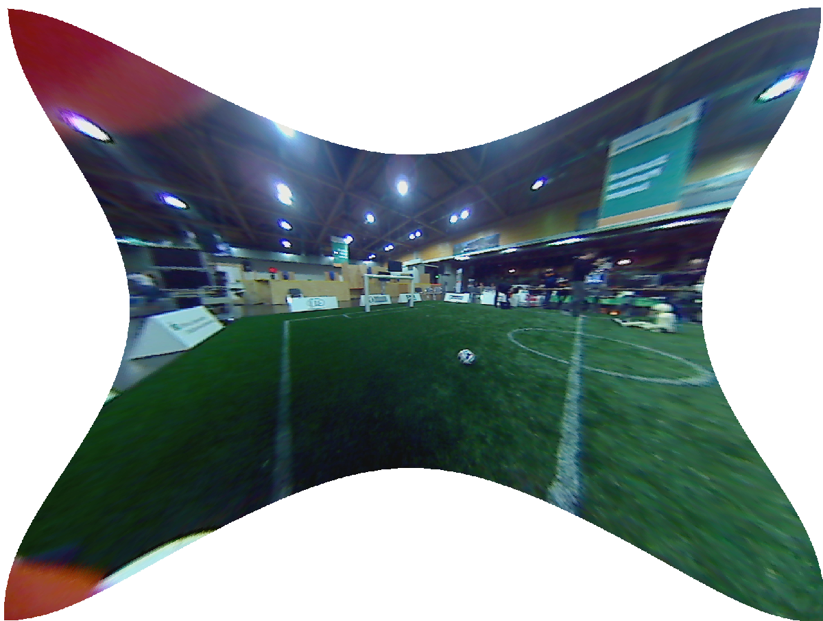
Due to the use of a wide-angle lens, a distortion model was required to be able to project points in the camera image into world coordinates. The distortion model used by OpenCV was adapted for the igus® Humanoid Open Platform, which uses two tangential and six radial distortion coefficients, in addition to the four standard intrinsic camera parameters. Due to incorrect performance of the OpenCV point undistortion function, a more efficient and accurate custom undistortion algorithm based on the Newton-Raphson method was designed and implemented. Fig. 8 illustrates the effect of undistortion on images captured by the robot.
IX Conclusion
The igus® Humanoid Open Platform represents a significant advancement over the previously released NimbRo-OP robot towards a robust, affordable, versatile, and customisable open standard platform for humanoid robots in the child-sized range. The robot has proven to have many positive mechanical attributes, due largely to its modular design and advanced 3D printing manufacturing process that allows for near arbitrary flexibility in the design. The complete mechanical and electrical subsystems of the robot have been described in this paper, in addition to selected features of the developed ROS software, which remains a continual development effort. We have released the hardware and software open source to the community in the hope that it will benefit other research groups around the world, and that it will encourage them to also publish their results as a contribution to the open source community.
X Acknowledgements
We would like to acknowledge the contributions of igus® GmbH to the project, in particular the management of Martin Raak towards the robot design and manufacture.
References
- [1] M. Quigley, K. Conley, B. P. Gerkey, J. Faust, T. Foote, J. Leibs, R. Wheeler, and A. Ng, “ROS: An open-source robot operating system,” in ICRA Workshop on Open Source Software, 2009.
- [2] igus GmbH. (2015, Oct) igus Humanoid Open Platform Hardware CAD Data. [Online]. Available: https://github.com/igusGmbH/HumanoidOpenPlatform
- [3] NimbRo. (2015, Oct) igus Humanoid Open Platform ROS Software. [Online]. Available: https://github.com/AIS-Bonn/humanoid_op_ros
- [4] D. Gouaillier, V. Hugel, P. Blazevic, C. Kilner, J. Monceaux, P. Lafourcade, B. Marnier, J. Serre, and B. Maisonnier, “Mechatronic design of NAO humanoid,” in Int. Conf. on Robotics and Automation, 2009.
- [5] I. Ha, Y. Tamura, H. Asama, J. Han, and D. Hong, “Development of open humanoid platform DARwIn-OP,” in SICE Annual Conf., 2011.
- [6] M. Lapeyre, P. Rouanet, J. Grizou, S. Nguyen, F. Depraetre, A. Le Falher, and P.-Y. Oudeyer, “Poppy Project: Open-Source Fabrication of 3D Printed Humanoid Robot for Science, Education and Art,” in Digital Intelligence 2014, Sep 2014.
- [7] K. Hirai, M. Hirose, Y. Haikawa, and T. Takenaka, “The development of Honda humanoid robot,” in Int. Conf. on Rob. and Autom., 1998.
- [8] K. Kaneko, F. Kanehiro, M. Morisawa, K. Miura, S. Nakaoka, and S. Kajita, “Cybernetic human HRP-4C,” in Proceedings of 9th IEEE-RAS Int. Conf. on Humanoid Robotics (Humanoids), 2009, pp. 7–14.
- [9] M. Schwarz, M. Schreiber, S. Schueller, M. Missura, and S. Behnke, “NimbRo-OP Humanoid TeenSize Open Platform,” in 7th Workshop on Humanoid Soccer Robots, Int. Conf. on Humanoid Robots, 2012.
- [10] P. Allgeuer, M. Schwarz, J. Pastrana, S. Schueller, M. Missura, and S. Behnke, “A ROS-based software framework for the NimbRo-OP humanoid open platform,” in 8th Workshop on Humanoid Soccer Robots, Int. Conference on Humanoid Robots, 2013.
- [11] M. Schwarz, J. Pastrana, P. Allgeuer, M. Schreiber, S. Schueller, M. Missura, and S. Behnke, “Humanoid TeenSize Open Platform NimbRo-OP,” in Proceedings of 17th RoboCup International Symposium, Eindhoven, Netherlands, 2013.
- [12] P. Allgeuer and S. Behnke, “Hierarchical and state-based architectures for robot behavior planning and control,” in Proceedings of 8th Workshop on Humanoid Soccer Robots, IEEE-RAS Int. Conference on Humanoid Robots, Atlanta, USA, 2013.
- [13] M. Schwarz and S. Behnke, “Compliant robot behavior using servo actuator models identified by iterative learning control,” in Proceedings of 17th RoboCup Int. Symposium, Eindhoven, Netherlands, 2013.
- [14] M. Felis. (2015, Jun) Rigid Body Dynamics Library. [Online]. Available: http://rbdl.bitbucket.org/
- [15] P. Allgeuer and S. Behnke, “Fused Angles: A representation of body orientation for balance,” in Int. Conf. on Intelligent Robots and Systems (IROS), Hamburg, Germany, 2015.
- [16] P. Allgeuer and S. Behnke, “Robust sensor fusion for biped robot attitude estimation,” in Proceedings of 14th IEEE-RAS Int. Conference on Humanoid Robotics (Humanoids), Madrid, Spain, 2014.
- [17] S. Behnke, “Online trajectory generation for omnidirectional biped walking,” in Proceedings of 2006 IEEE International Conference on Robotics and Automation, Orlando, USA, 2006.
- [18] M. Missura and S. Behnke, “Self-stable omnidirectional walking with compliant joints,” in Proceedings of 8th Workshop on Humanoid Soccer Robots, Int. Conf. on Humanoid Robots, 2013.