Higher-order topological electric circuits and topological corner
resonance
on the breathing Kagome and pyrochlore lattices
Abstract
Electric circuits are known to realize topological quadrupole insulators. We explore electric circuits made of capacitors and inductors forming the breathing Kagome and pyrochlore lattices. They are known to possess three phases (trivial insulator, higher-order topological insulator and metallic phases) in the tight-binding model, where the topological phase is characterized by the emergence of zero-energy corner states. A topological phase transition is induced by tuning continuously the capacitance, which is possible by using variable capacitors. It is found that the two-point impedance yields huge resonance peaks when one node is taken at a corner in the topological phase. It is a good signal to detect a topological phase transition. We also show that the topological corner resonance is robust against randomness of capacitance and inductance. Furthermore, the size of electric circuits can be quite small to realize the topological phase together with topological phase transitions.
Introduction: Topological insulators and its generalization to higher-order topological insulators Fan ; Science ; APS ; Peng ; Lang ; Song ; Bena ; Schin ; FuRot ; EzawaKagome ; Khalaf ; Switch are fascinating topics in condensed-matter physics (CMP). They are characterized by the bulk symmetry and the bulk topological numbers, and observed by the emergence of topological zero-energy boundary states. Especially, topological zero-energy corner states emerge for the second-order topological insulators (SOTI) in two dimensions and for the third-order topological insulators in three dimensions. They are robust against impurities. They are studied mainly in fermionic systems in materialsBis ; EzawaPhos ; MoTe . Actually, it is quite difficult to make experimental observation of topological corner states in CMP. Furthermore, although topological phase transitions have been extensively studied, the experimental observation is also very difficult in CMP. On the other hand, these topological corner states have already been observed experimentally in phononic systemPhonon ; Xue ; Alex , microwave systemMicrowave , photonic systemPhoton and electric circuitsTECNature .
Topological corner states in square lattice are experimentally realized in electric circuitsTECNature ; Garcia . Indeed, the Su-Schrieffer-Heeger modelComPhys ; Hel , the honeycomb latticeComPhys ; Hel and Weyl semimetalsComPhys ; Lu have already been implemented in electric circuits. The impedance is a measurable quantity determining whether the system is topological or not, where topological boundary resonance effects occur in the topological phases. Here we note that the emergence of topological corner states has been predictedEzawaKagome also in the breathing Kagome and pyrochlore lattices in the context of CMP. Thus, it is an interesting problem to study measurable quantities in topological electric circuits corresponding to these lattices.
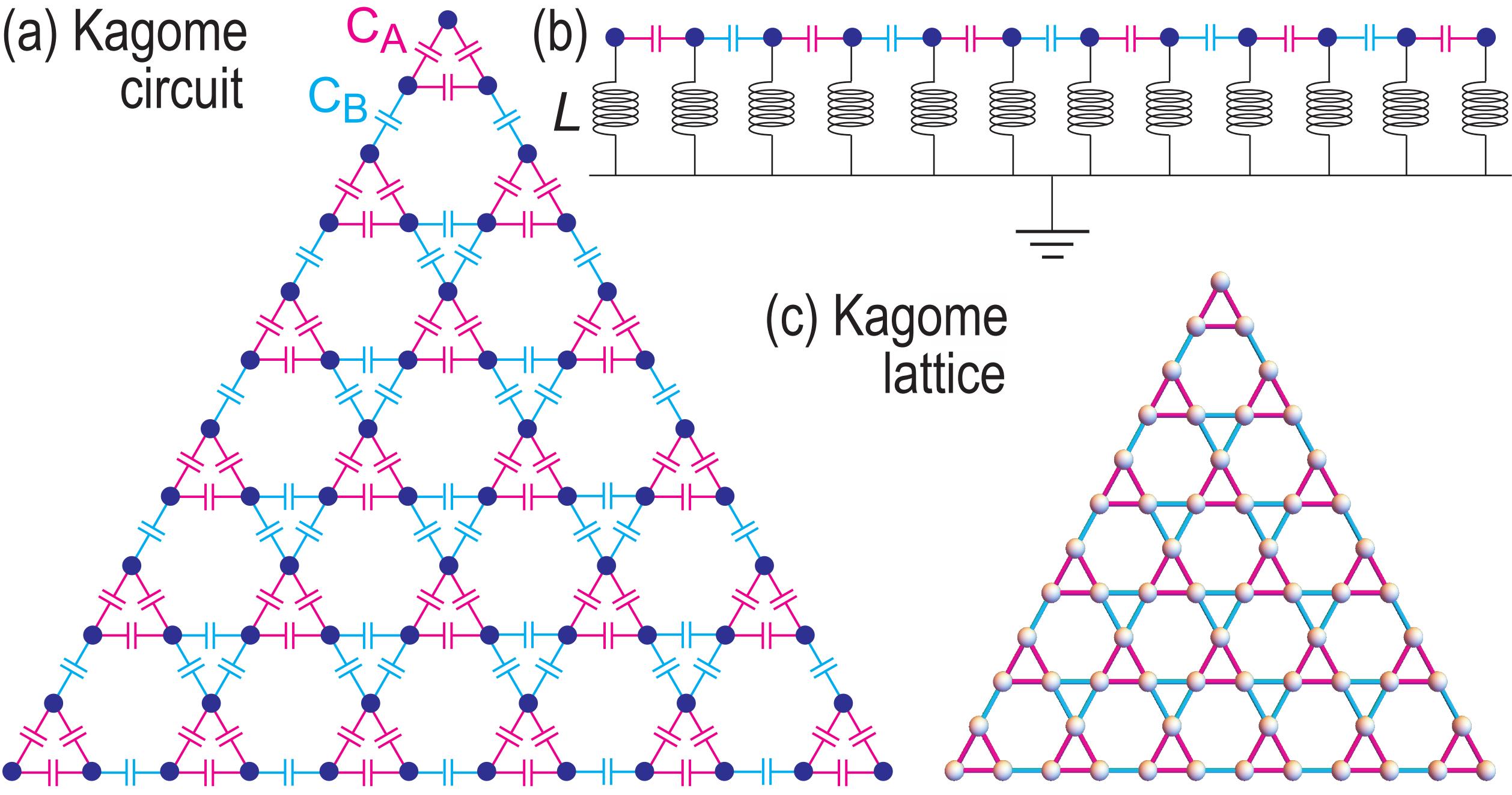
Let us explain how to construct a topological electric circuit by taking an instance of the breathing Kagome lattice. The breathing Kagome lattice consists of lattice sites and two types of links indicated in red and cyan as in Fig.1(c). We insert capacitors with capacitance and to links in red and cyan, respectively, as in Fig.1(a). Then, we connect each lattice site to the ground via an inductor with inductance , as illustrated in Fig.1(b). A lattice site is called a node in electric circuit. It is clear that this method is applicable to any lattices we encounter in CMP.
In this paper, we study electric circuits corresponding to the breathing Kagome and pyrochlore lattices. Topological phase transitions in electric circuits are well signaled by measuring the impedance, where huge resonance peaks emerge at corners in the topological phase. We find the topological robustness, that is, this resonance is robust against randomness of capacitance and inductance. We explicitly investigate a triangular geometry made of the breathing Kagome circuit, where we define its size by the number of small upper triangles along one edge: See Fig.1. We also study a tetrahedron geometry made of the breathing pyrochlore circuit.
Topological electric circuits: Electric circuits are characterized by the Kirchhoff’s current lawTECNature ; ComPhys ; Hel ,
| (1) |
where is the current between node and the ground, is the voltage at node , is the capacitance between nodes and , is the inverse of the inductance at node , and the sum is taken over all adjacent nodes . See an example of the breathing Kagome circuit in Fig.1. When we apply an AC field , the Kirchhoff’s law is rewritten as
| (2) |
with
| (3) |
where the matrix is called the circuit Laplacian. It is a linear operator and corresponds to a tight-binding Hamiltonian in CMP via the relation with the Hamiltonian beingTECNature ; ComPhys
| (4) |
The capacitor between adjacent nodes and corresponds to the transfer integral between adjacent sites and , while the inductor attached to node corresponds to the on-site potential at the site . Later we present an explicit correspondence in the case of the breathing Kagome lattice.
By diagonalizing the matrix we obtain the eigenvalue and the associated eigenmode . Then, we have . The eigenmode is a vector whose components are labelled by node ; . The admittance eigenvalue is a measurable quantityHel .
The two-point impedance is given byComPhys ; TECNature
| (5) |
and determined by measuring the voltage response by running a current between two nodes and . The key property is that diverges in the presence of zero-admittance modes () provided . Hence, the emergence of zero-admittance modes may be detected by measuring the two-point impedance.
Breathing Kagome circuit: The electric circuits corresponding to the honeycomb lattice have already been studiedComPhys ; Hel . Here we investigate them for the breathing Kagome lattice, which is known to realize a SOTI in CMP. We consider an infinite circuit which is periodic with a unit cell. It corresponds to a bulk system in CMP.
The circuit Laplacian (3) for an infinite circuit reads
| (6) |
where is the unit matrix and
| (7) |
with
| (8) |
Here, and are capacitances shown in Fig.1(a). We note that the Hamiltonian is precisely the same one that describes the tight-binding model for the breathing Kagome lattice by replacing and with the hopping parameters and , respectively: See Eq.(1) of Ref.EzawaKagome . Consequently, the system (7) for the breathing Kagome circuit is topological for , trivial for and metallic for . Consequently, the system undergoes topological phase transitions at between the trivial and topological phases, and at between the topological and metallic phases. In contrast to the case of CMP, it will be rather easy to make experimental observation of these phase transitions by tuning the capacitance continuously. We note that negative capacitance is possibleTECNature with the use of inductors by identifying .
We investigate the topological phase in triangular geometry [Fig.1(a)], where topological zero-admittance modes are present at the corners. Due to the presence of zero-admittance modes, the second term in the right-hand side of Eq.(6) vanishes. The resultant equation is a standard formula for the LC circuit with capacitance . The resonant frequency is given by the zero of the identity matrix and given by .
The behavior of the impedance around is expressed as
| (9) |
which yields a huge resonance peak at the frequency . There is no divergence because of the finite-size effect. On the other hand, when there are no zero-admittance modes, the impedance is finite. The metallic phase is intriguing due to the presence of the sea of zero-admittance modes. As we shall see soon, there is no resonance enhancement in . We expect that the emergence of the resonant modes is a signal that the electric circuit is in a topological phase.
When we use the capacitor of the order of 1F and the inductor of the order 1H, the resonance occurs around 1MHz and the impedance is of the order of 1, while the resonant impedance becomes to the order of .
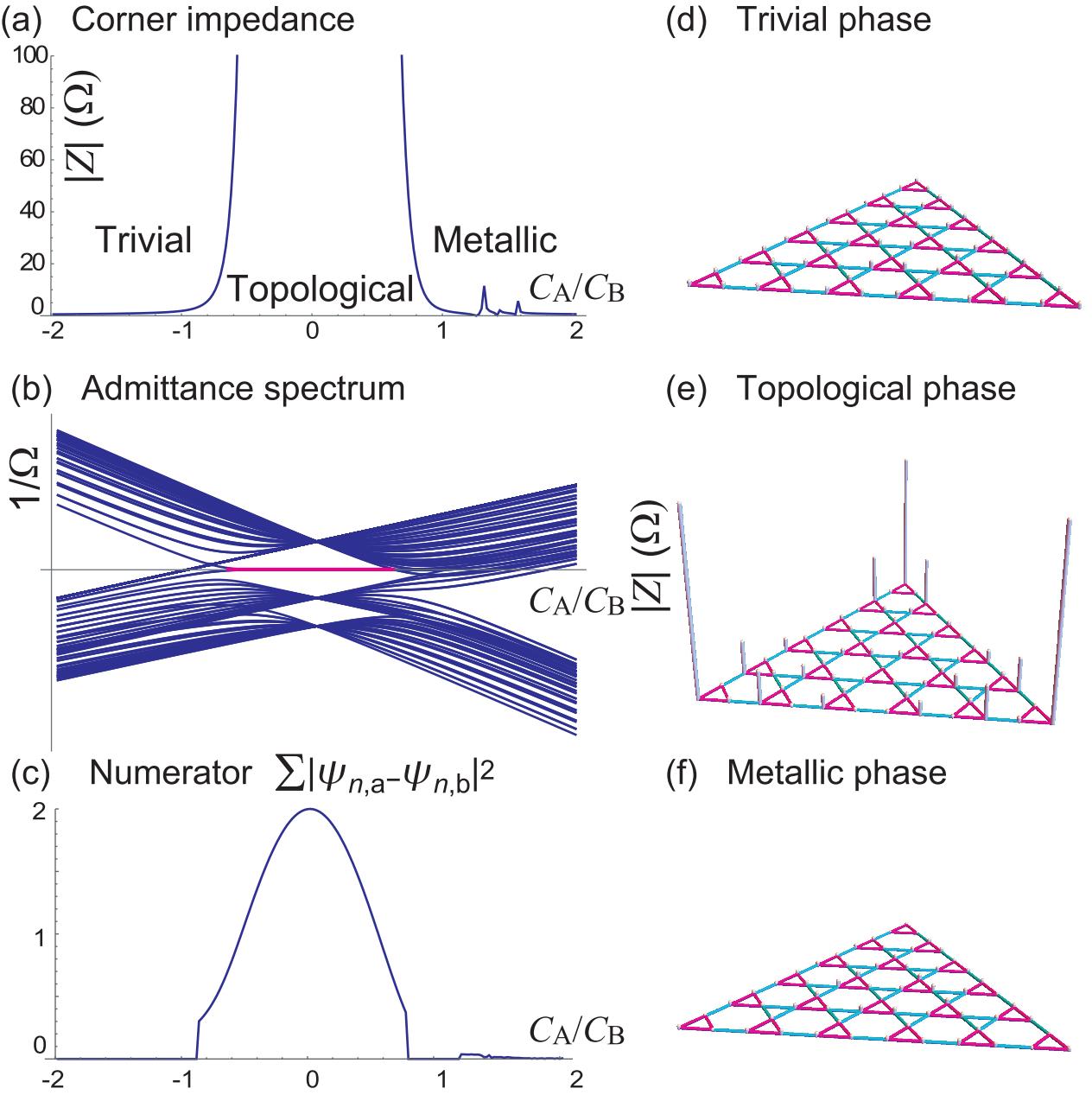
Corner impedance: We consider a triangle structure made of the breathing Kagome circuit [Fig.1]. We first show the admittance spectrum in Fig.2(b), where zero-admittance corner modes emerge only in the topological phase.
We next investigate the two-point impedance. We fix one node arbitrarily, and measure the impedance between node and another node . By moving over all nodes, we obtain a space distribution of the two-point impedance. We show the results in the three phases in Fig.2(d)–(f), where node is taken around the center of the triangle. The essential feature is a strong enhancement of the two-point impedance in the topological phase when node is taken at three corners. We have found that this essential feature does not depend on the position of the fixed node provided it is not taken on the corners. When node is taken on a corner, the strong enhancement appears only when node is taken at the other two corners because . The huge peak in is easily understood in the topological phase due to zero-admittance corner modes as we have discussed below Eq.(9). We find that the strongest resonance occurs when two nodes and are taken at two different corners.
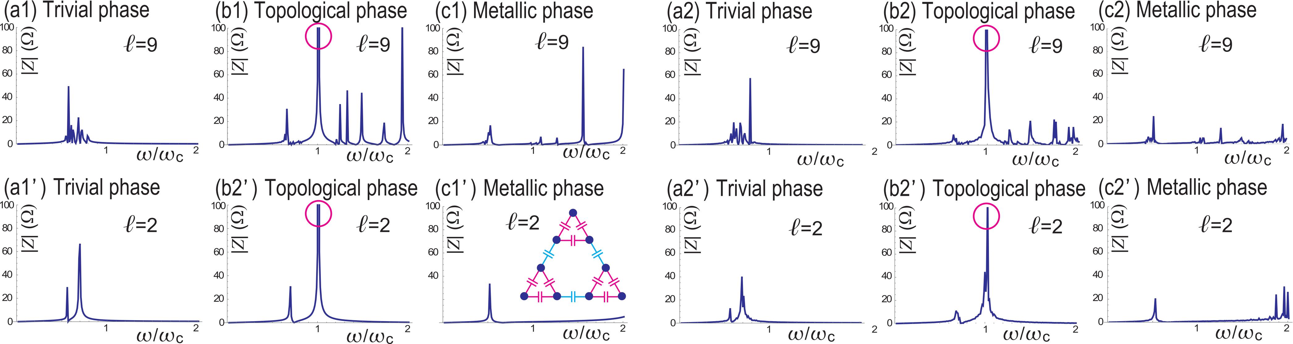
We show the two-point impedance in Fig.3, where the two nodes are fixed at two different corners. We show the impedance as a function of . The impedance displays a huge peak at in the topological phase, while there are no such peaks in the trivial phase and the metallic phase. We also show the impedance at the resonant frequency as a function of in Fig.2(a). It becomes huge rapidly in the topological phase, which implies that it is a good indicator to observe topological phases. Remarkably, the resonance peak signaling the topological phase is clearly present in such a small triangle that has the size : See Fig.3(a’)–(c’).
Naively, we expect that the impedance takes a large value also for metallic phase since there are many zero-admittance modes although they are not topological. However, this is not the case. We show the numerator as a function of , where the sum of is taken only for the three zero-admittance modes in Fig.2(c). It takes value around 2 only for the topological phase representing the two localization of the corner modes. On the other hand, in the metallic phase, it is very small, , where is the number of nodes. Accordingly, the impedance is small in the metallic phase although there are plenty of zero-admittance modes.
Effects of randomness: We next study the effects of randomness in capacitors and inductors. For this purpose, we make substitution and , where and are uniformly distributed random variables ranging from to . We have calculated the impedance by choosing .
We show the dependence of the impedance in Fig.3. The prominent peak signaling the topological resonance remains as it is. On the other hand, all other peaks are reduced. The results indicate the topological robustness of the topological corner resonance.
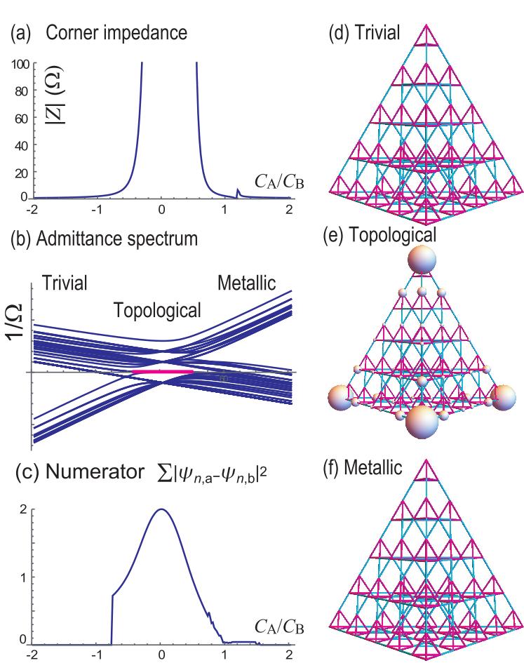
Breathing pyrochlore circuit: A natural extension of the breathing Kagome circuit to three dimensions is the breathing pyrochlore circuit, where a third-order topological insulator is realizedEzawaKagome . The circuit Laplacian is given by
| (10) |
where
| (11) |
with
| (12) |
The resonant frequency is . Topological phase diagram of the breathing pyrochlore circuit is the same as that of the breathing Kagome circuit. We show the admittance spectrum of the tetrahedron in Fig.4(b), where the four topological corner modes appear in the topological phase. We show the two-point impedance between two nodes as a function of in Fig.4(a), which becomes huge in the topological phase. We also show the numerator , where the sum of is taken only for the four zero-admittance modes in Fig.4(c). A space distribution of the two-point impedance is shown in the three phases in Fig.4(d)–(f).
Discussion: We have shown that the topological corner impedance is a good signal to detect a topological phase transition in electric circuits corresponding to the breathing Kagome and pyrochlore lattices, where the huge resonance peak emerges only in the topological phase. The topological phase transition is controlled by tuning variable capacitors. It is not necessary to tune the capacitance so precisely because of the topological robustness. Furthermore, to realize the topological phase together with topological phase transitions, the size of the electric circuit can be quite small.
The author is very much grateful to N. Nagaosa for helpful discussions on the subject. This work is supported by the Grants-in-Aid for Scientific Research from MEXT KAKENHI (Grants No. JP17K05490, No. JP15H05854 and No. JP18H03676). This work is also supported by CREST, JST (JPMJCR16F1).
References
- (1) F. Zhang, C.L. Kane and E.J. Mele, Phys. Rev. Lett. 110, 046404 (2013).
- (2) W. A. Benalcazar, B. A. Bernevig, and T. L. Hughes, 10.1126/science.aah6442.
- (3) F. Schindler, A. Cook, M. G. Vergniory, and T. Neupert, in APS March Meeting (2017).
- (4) Y. Peng, Y. Bao, and F. von Oppen, Phys. Rev. B 95, 235143 (2017).
- (5) J. Langbehn, Y. Peng, L. Trifunovic, F. von Oppen, and P. W. Brouwer, Phys. Rev. Lett. 119, 246401 (2017).
- (6) Z. Song, Z. Fang, and C. Fang, Phys. Rev. Lett. 119, 246402 (2017).
- (7) W. A. Benalcazar, B. A. Bernevig, and T. L. Hughes, Phys. Rev. B 96, 245115 (2017).
- (8) F. Schindler, A. M. Cook, M. G. Vergniory, Z. Wang, S. S. P. Parkin, B. A. Bernevig, and T. Neupert, Science Advances 4, eaat0346 (2018).
- (9) C. Fang, L. Fu, arXiv:1709.01929.
- (10) M. Ezawa, Phys. Rev. Lett. 120, 026801 (2018).
- (11) E. Khalaf, H. C. Po, A. Vishwanath and H. Watanabe, Phys. Rev. X 8, 031070 (2018).
- (12) M. Ezawa, Phys. Rev. Lett. 121, 116801 (2018).
- (13) F. Schindler, Z. Wang, M. G. Vergniory, A. M. Cook, A. Murani, S. Sengupta, A. Y. Kasumov, R. Deblock, S. Jeon, I. Drozdov, H. Bouchiat, S. Gueron, A. Yazdani, B. A. Bernevig, and T. Neupert, arXiv:1802.02585.
- (14) M. Ezawa, Phys. Rev. B 98, 045125 (2018).
- (15) Z. Wang, B. J. Wieder, J. Li, B. Yan, and B. A. Bernevig, arXiv:1806.11116.
- (16) M. S.-Garcia, V. Peri, R. Susstrunk, O. R. Bilal, T. Larsen, L. G. Villanueva, S. D. Huber, Nature 555, 342 (2018).
- (17) H. Xue, Y. Yang, F. Gao, Y. Chong and B. Zhang, cond-mat/arXiv:1806.09418.
- (18) X. Ni, M. Weiner, A. Alu, and A. B. Khanikaev, cond-mat/arXiv:1807.00896.
- (19) C. W. Peterson, W. A. Benalcazar, T. L. hughes and G. Bahl, Nature 555, 346 (2018).
- (20) B. Y. Xie, H. F. Wang, H.-X. Wang, X. Y. Zhu, J.-H. Jiang, M. H. Lu, Y. F. Chen, cond-mat/arXiv:1805.07555.
- (21) S. Imhof, C. Berger, F. Bayer, J. Brehm, L. Molenkamp, T. Kiessling, F. Schindler, C. H. Lee, M. Greiter, T. Neupert, R. Thomale, Nat. Phys. 14, 925 (2018).
- (22) M. S.-Garcia, R. Susstrunk and S. D. Huber, cond-mat/arXiv:1806.07367.
- (23) C. H. Lee , S. Imhof, C. Berger, F. Bayer, J. Brehm, L. W. Molenkamp, T. Kiessling and R. Thomale, Communications Physics, 1, 39 (2018).
- (24) T. Helbig, T. Hofmann, C. H. Lee, R. Thomale, S. Imhof, L. W. Molenkamp and T. Kiessling, cond-mat/arXiv:1807.09555.
- (25) Y. Lu, N. Jia, L. Su, C. Owens, G. Juzeliunas, D. I. Schuster and J. Simon, cond-mat/arXiv:1807.05243.