Stimulated Brillouin Scattering in layered media: nanoscale enhancement of silicon
Abstract
We report a theoretical study of Stimulated Brillouin Scattering (SBS) in general anisotropic media, incorporating the effects of both acoustic strain and local rotation in all calculations. We apply our general theoretical framework to compute the SBS gain for layered media with periodic length scales smaller than all optical and acoustic wavelengths, where such composites behave like homogeneous anisotropic media. We theoretically predict that a layered medium comprising nanometre-thin layers of silicon and As2S3 glass possesses a bulk SBS gain of . This is more than 500 times larger than the gain coefficient of silicon, and substantially larger than the gain of As2S3. The enhancement is due to a combination of roto-optic, photoelastic, and artificial photoelastic contributions in the composite structure.
Interactions between photons and phonons represent an important avenue of research in contemporary photonics and optomechanics van Laer et al. (2015); Florez et al. (2016); Otterstrom et al. (2018), not only for the transmission of light in optical fibres Boyd (2003); Powers (2011), but also for the design of efficient, small-scale optical devices Eggleton et al. (2013). One of the most important effects for driving these interactions is Stimulated Brillouin Scattering (SBS) Powers (2011). In bulk materials, SBS is frequently described as the resonant excitation of the first acoustic pressure mode of the medium by the optical pump field; the pressure wave acts as a travelling diffraction grating which scatters the pump and induces a Doppler-shifted returning (Stokes) wave. A significant issue with this description is that it only holds in optically isotropic media where bulk SBS interactions are only possible with longitudinal acoustic waves and not with shear acoustic waves. In materials possessing optical anisotropy, shear acoustic waves and mixed-polarised acoustic waves are also SBS-active Nelson and Lazay (1970a); Auld (1973); Nelson and Lazay (1977), due to reduced symmetry constraints Wolff et al. (2014a). Here we consider SBS more generally than is frequently described, defining the process as the inelastic resonant excitation of a bulk acoustic mode by the pump wave, leading to the formation of a backwards-propagating optical Stokes wave. A key issue with SBS in technologically relevant materials platforms, such as silicon, is intrinsically low SBS gain, which motivates considerable interest in novel designs for its enhancement (i.e., van Laer et al. (2015)). In recent years, composite materials have been explored theoretically as a means of controlling SBS Smith et al. (2015); Sun et al. (2015); Smith et al. (2016a, b); Su et al. (2017).
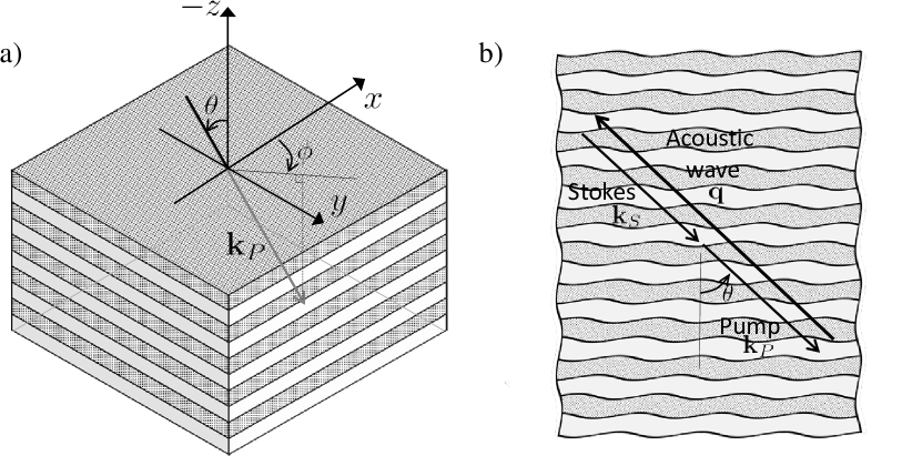
In this work, we present results for SBS in a layered medium, as shown in Fig. 1, where in addition to photoelastic processes (including artificial photoelasticity Smith et al. (2017), see below), we also have contributions to the SBS gain from induced optical anisotropy. By incorporating all relevant optoacoustic processes, we show that the gain coefficient of layered media takes values well above the SBS gain of the constituents in bulk. To demonstrate this point, we present results for a Si–As2S3 layered medium, where we find a gain coefficient of . Our gain value is two orders of magnitude larger than that of pure Si¡100¿ ( Smith et al. (2016a)), 75% larger than that of pure As2S3 ( Pant et al. (2011)), and an order of magnitude larger than results for a suspension of As2S3 spheres in Si ( Smith et al. (2016b)). To the authors’ knowledge this is the first study of SBS in layered media.
Such enhancements are achieved due to changes in the permittivity under changes in filling fraction (artificial photoelastic contributions), as well as changes to the permittivity under infinitesimal rotation (roto-optic contributions Toupin (1956); Nelson and Lazay (1970a, b); Nelson (1979); Vacher and Courtens (2006)), in addition to intrinsic photoelastic contributions from the layers Smith et al. (2017).
As an optoacoustic process, roto-opticity is not new Toupin (1956), but is much less well-known than conventional photoelasticity, as rotationally induced birefringence is not observed in materials of high symmetry. Artificial photoelastic effects are much more recent and were discovered by the authors in 2015 Smith et al. (2015). All microscopic-scale interactions are implicitly captured in the effective medium treatment, and are contained within the artificial electrostriction contributions (see discussion in Smith et al. Smith et al. (2017)). The nontrivial relationship between radiation pressure and artificial electrostrictrion is demonstrated by the fact that artificial contributions vanish in the absence of either a permittivity or stiffness contrast Smith et al. (2017) , whereas radiation pressure effects vanish in the absence of only a permittivity contrast Wolff et al. (2015). In materials possessing optical isotropy and acoustic anisotropy, such as Germanium, a material frame rotation has been shown to improve the confinement of longitudinal acoustic modes for SBS Wolff et al. (2014b).
We begin by presenting a generalisation of the coupled-mode approach in Wolff et al. Wolff et al. (2015) for evaluating the SBS gain of uniform anisotropic media. Assuming linear constitutive behaviour in both the optical and acoustic properties, the SBS gain coefficient (in the absence of irreversible forces) is defined as Wolff et al. (2015)
| (1) |
where (units ) denotes the total electrostrictive coefficient, is the pump intensity (units ), is the Stokes intensity (units ), and is the acoustic intensity (units ), where all intensities are associated with the modes of the optical and acoustic waves in the material. Here, is the acoustic attenuation constant (units ). These are given by
| (2a) | ||||
| (2b) | ||||
| (2c) | ||||
| (2d) | ||||
| (2e) | ||||
respectively, where is the relative permittivity tensor, is the acoustic displacement from equilibrium, and are the electric and magnetic field vectors for the pump and Stokes fields, respectively. Additionally, is the normalised group velocity for the pump field, is the Levi-Civita tensor, is the stiffness tensor, and is the phonon viscosity tensor. Finally, and are the angular frequencies of the pump field and the acoustic wave, respectively, and is the linear strain tensor. Here we define via Nelson and Lax (1970)
| (3a) | |||
| where the full photoelastic tensor decomposes as | |||
| (3b) | |||
for non-piezoelectric dielectric materials, with and denoting the symmetric and antisymmetric (roto-optic) photoelastic tensors, respectively. Following Nelson and Lax (1970), we represent index pair interchange symmetry with parentheses and interchange antisymmetry with square brackets. Note that (3b) represents a key departure from conventional treatments of SBS, as in optically isotropic materials Nelson et al. (1972).
To evaluate (1), it is necessary to determine a large number of modal fields belonging to several different families. For determining the optical fields and quantities in (2), such as wave polarisations and the refractive index, we consider Maxwell’s equations with the plane wave ansatz where denotes the polarisation of the wave, and is the wave vector. This ansatz admits the system Born and Wolf (1964)
| (4) |
where , is the wave number, is the refractive index, and denotes the speed of light in vacuum. Subsequently, for a given wave vector , the supported refractive indices are obtained by solving and the associated eigen-polarisations are given by the eigenvectors of . The corresponding group velocity of the wave () is obtained by implicit differentiation of (4).
In order to determine the properties of the available Stokes waves for a given pump wave vector , namely the wave vectors and wave polarisations , we impose that the direction of the group velocity vector for the Stokes wave is opposite in sign to that of the pump wave (), which is consistent with backwards SBS coupling. From this group velocity condition, the properties of the Stokes wave are obtained following the procedure above for the pump wave.
To determine acoustic fields and quantities, we consider the acoustic wave equation Auld (1973) assuming the plane wave ansatz , where is the polarisation, and the acoustic wave vector is defined by Boyd (2003); Powers (2011). Subsequently, we obtain the eigenvalue problem
| (5) |
which returns as eigenvalues and as eigenvectors, where denotes the mass density and the phase velocity of the wave. The Christoffel tensor is widely tabulated for a broad selection of Bravais lattice classes Auld (1973); Nye (1985); Newnham (2004).
We now proceed to a numerical study examining the SBS performance of Si-As2S3 layered media with a unit cell length of and at a vacuum wavelength . Even though the layered media consists of an acoustically isotropic and cubic medium, the composite medium is optically uniaxial. In Eqs. (1)-(3b) above, we use the closed-form expressions for , , , , and derived in Smith et al. Smith et al. (2017) for laminate materials possessing tetragonal () symmetry (i.e., when the constituent layers possess isotropic or cubic symmetry). These descriptions are valid provided the wavelengths of all optical and acoustic waves are much longer than the periodic length scale of the laminate; in this regime the behaviour of the composite material is accurately described by an effective uniform material. Material constants for the constituent layers are given in Smith et al. Smith et al. (2016a).
For the tetragonal laminates we consider, two pump waves are generally supported for wave vectors oriented away from directions of high symmetry (one for the extraordinary and another for the ordinary surface). Thus, for a specified in a bulk uniaxial crystal, up to four pair combinations of pump and Stokes waves may contribute to an SBS process. For each combination of pump and Stokes wave field, there are up to three acoustic wave polarisations supported at long wavelengths, giving a total of twelve possible combinations of pump, Stokes, and acoustic waves to participate in an SBS process in a tetragonal () material for a given . In a composite material, the symmetric photoelastic tensor defined in (3b) may be decomposed further as
| (6) |
representing some weighted average of constituent photoelastic terms and artificial photoelasticity coefficients, respectively Smith et al. (2017).
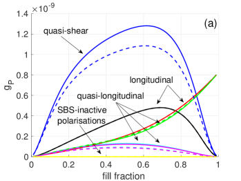
In Fig. 2(a) we present the gain coefficient as a function of filling fraction for all twelve possible combinations of pump, Stokes, and acoustic wave polarisations (henceforth we refer to each of these twelve combinations as branches) corresponding to . This particular wave vector corresponds to the maximum possible gain value of for this material pair, which occurs at (note that two other orientations return the same , see below). Superimposed on this figure are the twelve branches for this structure when roto-optic contributions are neglected, returning a maximum gain value of at , and ultimately revealing a roto-optic enhancement of 19% to the . These dashed curves also allow us to identify the shear contribution to each mode as a function of filling fraction, revealing that the medium-gain branches (depicted by the black, red, and green curves in Fig. 2(a)) are almost purely longitudinal acoustic modes, for example. At filling fractions of approximately and higher, the greatest gain value is achieved for a longitudinally polarised acoustic mode (red curve), which is the only acoustic polarisation that is SBS-active in isotropic materials. Recall that pure Si¡100¿, corresponding to , possesses an intrinsically low SBS performance with Smith et al. (2016a). At we obtain for pure As2S3, which is marginally higher than experimental results ( in As2S3) Pant et al. (2011). Note also that half of the available mode branches are not SBS-active for any filling fraction. If we decompose the total electrostrictive coefficient in (1) as , where refers to intrinsic photoelastic contributions alone, artificial contributions alone, and the gain due to roto-optic contributions alone, we find that these quantities amount to 74%, 18%, and 8% of the overlap for the maximum gain value observed in Fig. 2(a), respectively. The modest contributions and are responsible for significant increases in the gain following (1), and highlight the importance of accurately capturing all optomechanical processes for SBS calculations in composites. To summarise, we find a maximum gain of at and , where , , and (materials tensors are also summarised in Table 1).
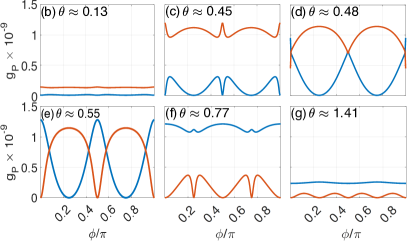
In Figs. 2(b-g), we consider the gain coefficient at fixed filling fraction as we examine the parameter space for the pump wave vector, i.e. for , where is measured relative to the axis of Si and the layers are stacked along . Specifically, we present the gain along (equatorial plane) as we sweep meridional angles . In this instance, only the two largest and competing branches are shown for clarity. These figures clearly demonstrate the importance of correctly orienting the pump wave vector, as particular orientation angles correspond to gain suppression (i.e., at and ), and that the maximum gain value occurs not only at a single pump wave vector. That is, the maximum SBS gain is achieved at three pump wavevectors corresponding to with . For the maximum gain branch (blue curve) shows that the incident wave vector must be appropriately oriented to achieve maximal results, however, the presence of the second acoustic branch (red curve) ensures that the gain coefficient does not take values beneath . Interestingly, all figures demonstrate the intense competition between acoustic mode branches for the maximum gain position, in addition to revealing intrinsic symmetries for the gain parameter in layered media as a function of the direction.
In Fig. 3 we examine the gain coefficient for the layered medium () along , when both roto-optic and artificial photoelastic contributions are neglected. Also superimposed are the total gain coefficient curves from Fig. 2(a) for reference. Here, we find that the estimated gain for layered media in the absence of these two contributions is significantly reduced (in particular, the maximum gain occurs at with ). At we find and subsequently establish that artificial and roto-optic effects increase the maximum SBS gain coefficient observed in Fig. 2(a) by approximately .

In summary, we have presented a theoretical framework for investigating SBS in anisotropic materials, and using this framework we propose a nanoscale layered material with an SBS coefficient that outperforms leading materials platforms. The structure we propose represents an enhancement in the SBS performance of silicon by more than two orders of magnitude, and is achieved by incorporating contributions from the symmetric photoelastic tensor (containing artificial photoelastic contributions only present in composite media), as well as contributions from the antisymmetric photoelastic tensor (roto-optic tensor), where the latter effect arises in all optically anisotropic media. We have also shown that artificial photoelastic and roto-optic contributions are non-negligible in optically anisotropic materials, contributing significantly to the total gain coefficient for our Si-As2S3 structure. For this material pair, the gain coefficient of the layered medium is larger than that of the embedded array medium Smith et al. (2016b), due to stronger artificial contributions and the emergence of roto-optic contributions. The framework presented here provides extensive scope for the ongoing development of new materials for future photonics and optomechanics research.
| Physical quantity | |||||||||||||||
|---|---|---|---|---|---|---|---|---|---|---|---|---|---|---|---|
| Effective parameter | 8.11 | 7.08 | 68.2 | 28.4 | 9.9 | 21.1 | 9.9 | 34.6 | 2.63 | 2.46 | 2.05 | 2.13 | 0.25 | 0.35 | 2864 |
| Physical quantity | |||||||||||||
|---|---|---|---|---|---|---|---|---|---|---|---|---|---|
| Effective parameter | 0.015 | 0.258 | 0.143 | 0.107 | 0.209 | -0.0004 | -0.0422 | 0.012 | 0.03 | 0.031 | 0.012 | 0.012 | 0.009 |
Funding. Australian Research Council (ARC) (CE110001018, DP160101691). C. Wolff acknowledge funding from MULTIPLY fellowships under the Marie Skłodowska-Curie COFUND Action (grant agreement No. 713694).
References
- van Laer et al. (2015) R. van Laer, B. Kuyken, D. van Thourhout, and R. Baets, Nat. Photon. 9, 199 (2015).
- Florez et al. (2016) O. Florez, P. F. Jarschel, Y. A. Espinel, C. Cordeiro, T. M. Alegre, G. S. Wiederhecker, and P. Dainese, Nat. Comm. 7, 11759 (2016).
- Otterstrom et al. (2018) N. T. Otterstrom, R. O. Behunin, E. A. Kittlaus, Z. Wang, and P. T. Rakich, Science 360, 1113 (2018).
- Boyd (2003) R. W. Boyd, Nonlinear optics (Elsevier, New York, 2003).
- Powers (2011) P. E. Powers, Fundamentals of nonlinear optics (CRC Press, Boca Raton, 2011).
- Eggleton et al. (2013) B. J. Eggleton, C. G. Poulton, and R. Pant, Adv. Opt. Photon. 5, 536 (2013).
- Nelson and Lazay (1970a) D. F. Nelson and P. D. Lazay, Phys. Rev. Lett. 25, 1187 (1970a).
- Auld (1973) B. A. Auld, Acoustic fields and waves in solids (John Wiley & Sons, Toronto, 1973).
- Nelson and Lazay (1977) D. F. Nelson and P. D. Lazay, Phys. Rev. B 16, 4659 (1977).
- Wolff et al. (2014a) C. Wolff, M. J. Steel, and C. G. Poulton, Opt. Exp. 22, 32489 (2014a).
- Smith et al. (2015) M. J. A. Smith, B. T. Kuhlmey, C. M. de Sterke, C. Wolff, M. Lapine, and C. G. Poulton, Phys. Rev. B 91, 214102 (2015).
- Sun et al. (2015) W. Sun, S. Wang, J. Ng, L. Zhou, and C. T. Chan, Phys. Rev. B 91, 235439 (2015).
- Smith et al. (2016a) M. J. A. Smith, B. T. Kuhlmey, C. M. de Sterke, C. Wolff, M. Lapine, and C. G. Poulton, Opt. Lett. 41, 2338 (2016a).
- Smith et al. (2016b) M. J. A. Smith, B. T. Kuhlmey, C. M. de Sterke, C. Wolff, M. Lapine, and C. G. Poulton, J. Opt. Soc. Am. B 33, 2162 (2016b).
- Su et al. (2017) X.-X. Su, X.-S. Li, Y.-S. Wang, and H. P. Lee, J. Opt. Sci. Am. B 34, 2599 (2017).
- Smith et al. (2017) M. J. A. Smith, C. M. de Sterke, C. Wolff, M. Lapine, and C. G. Poulton, Phys. Rev. B 96, 064114 (2017).
- Pant et al. (2011) R. Pant, C. G. Poulton, D.-Y. Choi, H. Mcfarlane, S. Hile, E. Li, L. Thevenaz, B. Luther-Davies, S. J. Madden, and B. J. Eggleton, Opt. Exp. 19, 8285 (2011).
- Toupin (1956) R. A. Toupin, J. Ration. Mech. Anal. 5, 849 (1956).
- Nelson and Lazay (1970b) D. F. Nelson and P. D. Lazay, Phys. Rev. Lett. 25, 1638 (1970b).
- Nelson (1979) D. F. Nelson, Electric, optic, and acoustic interactions in dielectrics (John Wiley & Sons, New York, 1979).
- Vacher and Courtens (2006) R. Vacher and E. Courtens, in International Tables for Crystallography, Vol. D, edited by A. Authier (International Union of Crystallography, Chester, 2006) Chap. 2.4, pp. 329–335.
- Wolff et al. (2015) C. Wolff, M. J. Steel, B. J. Eggleton, and C. G. Poulton, Phys. Rev. A. 92, 013836 (2015).
- Wolff et al. (2014b) C. Wolff, R. Soref, C. G. Poulton, and B. J. Eggleton, Opt. Exp. 22, 30735 (2014b).
- Nelson and Lax (1970) D. F. Nelson and M. Lax, Phys. Rev. Lett. 24, 379 (1970).
- Nelson et al. (1972) D. F. Nelson, P. D. Lazay, and M. Lax, Phys. Rev. B 6, 3109 (1972).
- Born and Wolf (1964) M. Born and E. Wolf, Principles of optics: electromagnetic theory of propagation, interference and diffraction of light (Pergamon Press, New York, 1964).
- Nye (1985) J. F. Nye, Physical properties of crystals: their representation by tensors and matrices (Oxford university press, Suffolk, 1985).
- Newnham (2004) R. E. Newnham, Properties of Materials: Anisotropy, Symmetry, Structure (Oxford University Press, New York, 2004).